Sign In
Upload
Manuals
Brands
Curtis Manuals
Controller
1222
Curtis 1222 Manuals
Manuals and User Guides for Curtis 1222. We have
1
Curtis 1222 manual available for free PDF download: Manual
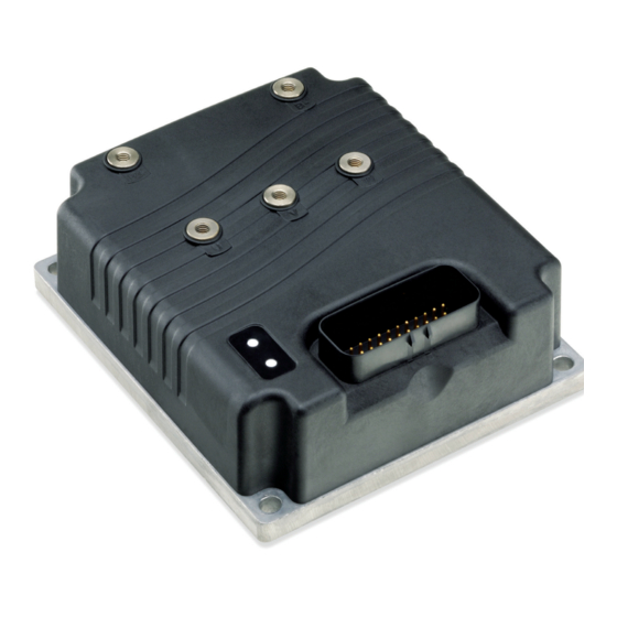
Curtis 1222 Manual (125 pages)
Electric Steering Controller
Brand:
Curtis
| Category:
Controller
| Size: 2.67 MB
Table of Contents
Table of Contents
3
Figures
4
Tables
4
1 Overview
5
Advanced Motor Control
5
Fig. 1: Curtis 1222 Controller
5
Maximum Safety
6
Unmatched Flexibility
6
Versatile Steering Input and Feedback Options
6
Robust Reliability
7
2 Installation and Wiring
8
Mounting the Controller
8
Fig. 2: Mounting Dimensions, Curtis 1222 Controller
8
Lug Assembly
10
High Current Wiring Recommendations
10
Battery Cables (B+, B-)
10
High Current Connections and Wiring Guidelines
10
Table 1 High Current Connections
10
Motor Wiring (U, V, W)
11
CAN Connection
12
Command Input Encoder and Steer Motor Encoder
12
Low Current Wiring Recommendations
12
Low Current Connections and Wiring Guidelines
12
Table 2 Low Current Connections
13
CONTROLLER WIRING: Safety Requirements
15
Fig. 3A: Wiring Diagram
15
Fig. 3B Software Control Diagram
16
Input/Output Signal Specifications
17
Digital Inputs
17
Digital Input Specifications
17
Driver Output Specifications
17
Analog Inputs
18
Analog Input Specifications
18
Power Supply Outputs
18
Power Supply Output Specifications
18
Keyswitch Input and Coil Return
19
Keyswitch and Coil Return Input Specifications
19
Communications Ports
19
Communications Port Specifications
19
Encoder Inputs
20
Encoder Input Specifications
20
3 Programmable Parameters
21
Parameter Attributes
21
Parameter Change Fault (PCF)
21
Parameter Menu Charts
21
Program Menu
22
Table 3 Programmable Parameter Menus
22
Input Device Parameter
24
Fig. 4: Command Input Device "0" Signal Flow
28
Fig. 5: Command Input Device "1" Signal Flow
29
Fig. 6 Command Input Device "2" Signal Flow
31
Command Input Device 3 – Sawtooth Sensor
32
Fig. 7 Command Input Device "3" Signal Flow
33
Command Input Device 4 – Can
34
Fig. 8 Command Input Device "4" Signal Flow
34
Fig. 9 Steer Command Map
35
Force Feedback Menu
37
Force Feedback Signal Flow
37
Feedback Device Parameter
38
Position Feedback Device
38
Fig. 10: Position Feedback Device "0" Signal Flow
41
Fig. 11: Position Feedback Device "1" Signal Flow
42
Fig. 12: Position Feedback Device "2" Signal Flow
45
Position Feedback Device 2 – Sin/Cos Sensor
45
Fig. 13: Position Feedback Device "3" Signal Flow
46
Position Feedback Device 3 – Sawtooth Sensor
46
Vehicle Configuration Menu
47
Vehicle Configuration: Steer Contactor
48
Vehicle Configuration: Traction Speed Input
49
Supervision Menu
50
Supervision: Following Error
51
Motor Menu
52
Motor: Temperature Control
53
Motor: User-Defined Temperature Sensor
54
Canopen MENU
55
Motor Control Tuning Menu
56
Fig. 14 Position Control Signal Flow
57
Fig. 15 Velocity Control Signal Flow
57
Fig. 16 Steering Sensitivity Map
58
Motor Control Tuning: Steering Sensitivity
58
Motor Control Tuning: Field Weakening Control
59
Motor Type Parameter
60
4A. MONITOR MENU
61
Table 4: Monitor Menu
61
Monitor Menu: COMMAND INPUT
62
Monitor Menu: CAN STATUS
72
4B. CONTROLLER INFORMATION MENU
74
4C. CONTROLLER FUNCTIONS MENU
75
5 Commissioning
76
Before You Start
76
Preparation for Commissioning
78
Steer Direction
79
Command Map Setup
80
Command Input Device Setup
80
Setup for Sin/Cos Sensor Input
82
Setup for CAN Sensor Input
85
Position Feedback Device Setup
88
Setup for Pot Feedback
88
Setup for Encoder Feedback and Home Switch
89
Calculation Method
90
Testing Method
90
Setup for Sin/Cos Sensor Feedback
91
Setup for Sawtooth Sensor Feedback
92
Set the Remaining Performance and Supervision Parameters
93
Verify the Position Feedback Setup
94
Resolve any Existing Faults
94
Set the Following Error Parameters
95
Set the Remaining Supervision Parameters
96
6 Interface with Master Controller
97
Can Messages
97
PDO Message Configuration
97
Emergency Message Configuration
98
Generic Ac Traction Controller Software
99
Severe Steering Fault
99
Steering Fault
99
Fig. 17A: Input Command Signal Flow
100
Fig. 17B: Position Feedback Signal Flow
101
Fig. 17C: Position/Velocity Control Signal Flow
102
Diagnostics & Troubleshooting
103
Example: Command Analog3 out of Range (Code 42)
103
Summary of LED Display Formats
104
Troubleshooting
104
Table 5 TYPES of LED DISPLAY
104
Table 6: Troubleshooting Chart
105
8 Maintenance
114
Cleaning
114
Removal
114
Fault History
115
Electromagnetic Compatibility (Emc)
117
Emissions
117
Immunity
117
APPENDIX A Vehicle Design Considerations
117
Electrostatic Discharge (Esd)
119
Fig. B-1: Supervisory System
120
Programming Devices
122
Pc Programming Station (1314)
122
Handheld Programmer (1313)
122
Programmer Functions
122
Specifications
123
Advertisement
Advertisement
Related Products
Curtis MultiMode 1228
Curtis 1220
Curtis 1221M
Curtis 1226
Curtis 1204
Curtis 1238E
Curtis 1205M
Curtis 1238
Curtis 1234
Curtis MultiMode 1214-8
Curtis Categories
Coffee Maker
DVD Player
LCD TV
MP3 Player
Clock Radio
More Curtis Manuals
Login
Sign In
OR
Sign in with Facebook
Sign in with Google
Upload manual
Upload from disk
Upload from URL