Table of Contents
Advertisement
Manual
Model 1253
Hydraulic Pump Motor Controller
Read Instructions Carefully!
Specifications are subject to change without notice.
© 2015 Curtis Instruments, Inc. ® Curtis is a registered trademark of Curtis Instruments, Inc.
© The design and appearance of the products depicted herein are the copyright of Curtis Instruments, Inc.
Curtis Instruments, Inc.
200 Kisco Avenue
Mt. Kisco, NY 10549
www.curtisinstruments.com
38329 Rev F 2/15
Advertisement
Table of Contents
Troubleshooting

Subscribe to Our Youtube Channel
Related Manuals for Curtis 1253


Summary of Contents for Curtis 1253
- Page 1 Specifications are subject to change without notice. © 2015 Curtis Instruments, Inc. ® Curtis is a registered trademark of Curtis Instruments, Inc. © The design and appearance of the products depicted herein are the copyright of Curtis Instruments, Inc. 38329 Rev F 2/15...
-
Page 3: Table Of Contents
Low Voltage Cutback ..........27 Low Voltage Cutback Rate ..........27 Contactor Control Parameters ...........27 Pump Contactor Control ..........27 Contactor Pull-in Voltage ..........27 Contactor Holding Voltage..........27 SS4 Delay ..............28 Interlock Delay ............28 Precharge ..............28 Precharge Delay ............28 Curtis 1253 Manual, Rev. F... - Page 4 4. INSTALLATION CHECKOUT ..........30 5. DIAGNOSTICS AND TROUBLESHOOTING ....32 Programmer Diagnostics ............32 LED Diagnostics ..............34 6. MAINTENANCE ..............35 Vehicle Design Considerations appendix a Programming Devices and Menus appendix b Specifications, Curtis 1253 Controller appendix c Curtis 1253 Manual, Rev. F...
- Page 5 Curtis 1253 hydraulic system controller ........1 fig. 2: Mounting dimensions, Curtis 1253 controller ......3 fig. 3a: Standard wiring configuration, using Curtis 803 gauge for lift lockout ........7 fig. 3b: Standard wiring configuration, using Curtis 906 gauge for lift lockout ........8 fig. 3c: Standard wiring configuration,...
- Page 6 3: Programmable lift lockout signal types ....... 25 table 4: Precharge function and fault detection......... 28 table 5: Troubleshooting chart ............33 table 6: Status LED fault codes ............34 table C-1: Specifications, 1253 controller .......... C-1 Curtis 1253 Manual, Rev. F...
-
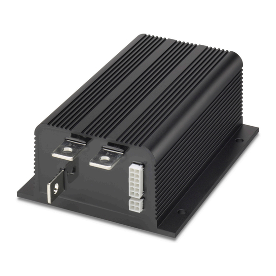
Page 7: Overview
(scissor lifts, articulating/ telescoping booms), and other industrial vehicles. The 1253 accepts inputs from up to four Speed Select switches and also from an analog throttle. Its internal microprocessor-based logic controller pro- vides maximum flexibility at minimum cost. Its performance characteristics can be tailored through an array of programmable parameters. - Page 8 ✓ Full-power operation over the -40°C – 80°C heatsink temperature range. Familiarity with your Curtis controller will help you install and operate it prop- erly. We encourage you to read this manual carefully. If you have questions, please contact the Curtis office nearest you.
-
Page 9: Installation And Wiring
INSTALLATION AND WIRING MOUNTING THE CONTROLLER The 1253 controller can be oriented in any position, and meets the IP54 ratings for environmental protection against dust and water. However, the location should be carefully chosen to keep the controller clean and dry. If a clean, dry mounting location cannot be found, a cover must be used to shield the controller from water and contaminants. - Page 10 — Charging or discharging generates hydrogen gas, LEAD ACID BATTERIES which can build up in and around the batteries. Follow the battery man- ufacturer’s safety recommendations. Wear safety glasses. Curtis 1253 Manual, Rev. F...
-
Page 11: Low Current Connections
2 — INSTALLATION & WIRING: Controller LOW CURRENT CONNECTIONS Two low current connectors are built into the 1253 controller. They are located on the end of the controller: The 12-pin connector (J1) provides the logic control connections. The mating connector is a 12-pin Molex Mini-Fit Jr. connector part number 39-01-2125 using type 5556 terminals. -
Page 12: High Current Connections
The throttle shown is a 3-wire pot; other types of throttles can also be used. Lift lockout can be provided through any of four Curtis gauges: (a) Curtis 803 (b) Curtis 906 (c) Curtis 841 “Superspy”... -
Page 13: Wiring: Standard Configuration
Lift lockout is activated when the 803’s internal relay between pins 3 and 4 is opened at 80% battery discharge. LOCKOUT TYPE should be programmed to 1. Fig. 3a Standard wiring configuration, Curtis 1253 controller with Curtis 803 providing lift lockout. Curtis 1253 Manual, Rev. F... -
Page 14: Fig. 3B Standard Wiring Configuration
Lift lockout is activated when pin 3 of the 906 drops from 5 V to 0 V at 80% battery discharge. LOCKOUT TYPE should be programmed to 0. Fig. 3b Standard wiring configuration, Curtis 1253 controller with Curtis 906 providing lift lockout. Curtis 1253 Manual, Rev. F... -
Page 15: Fig. 3C Standard Wiring Configuration
Lift lockout is activated when the 841’s internal relay between pins 3 and 4 is opened at 80% battery discharge. LOCKOUT TYPE should be programmed to 1. Fig. 3c Standard wiring configuration, Curtis 1253 controller with Curtis 841 “Superspy” providing lift lockout. Curtis 1253 Manual, Rev. F... -
Page 16: Fig. 3D Standard Wiring Configuration
J1-14, -15, or -16, depending on the gauge’s configuration. LOCKOUT TYPE should be programmed to 0. Fig. 3d Standard wiring configuration, Curtis 1253 controller with Curtis enGage ™ IV providing lift lockout. Curtis 1253 Manual, Rev. F... -
Page 17: Wiring: Throttles
2 — INSTALLATION & WIRING: Throttles WIRING: Throttles Various throttles can be used with the 1253 controller. They are categorized as one of four types in the Program Menu. Type 0: two-wire 0–5kΩ potentiometer throttles Type 1: two-wire 5kΩ–0 potentiometer throttles Type 2: single-ended 0–5V throttles... -
Page 18: Fig. 4: Wiring For 2-Wire 5Kω-0 Potentiometer ("Type 0")
This provides broken wire protection, and also serves as an indication that the potentiometer’s resistance has increased beyond the acceptable range and that the pot therefore needs to be replaced. Curtis 1253 Manual, Rev. F... -
Page 19: Contactor, Switches, And Other Hardware
The 3-wire potentiometer is used in its voltage divider mode, with the voltage source and return being provided by the 1253 controller. Pot High provides a current limited 5V source to the pot, and Pot Low provides the return path. - Page 20 The 1253 provides a low-side contactor coil driver (at Pin J1-12) for the main contactor. The driver output is rated at 1 amp and is short-circuit protected.
-
Page 21: Programmable Parameters
1314 PC Programming Station. The discontinued 1307 handheld programmer is also fully compatible with the 1253 controller. note: The 1311 hand- Curtis offers two versions of the 1311 programmer: the 1311-1101 is the held programmer has been superseded; if you... -
Page 22: Speed Parameters
3 — PROGRAMMABLE PARAMETERS: Speed and Throttle Parameters Speed Parameters The 1253 controller can accept inputs from up to four individual speed select switches (SS1–SS4) and from an analog throttle. The controller adjusts the pump motor’s PWM output in response to these inputs, using the algorithm prescribed by the programmed acceleration rate to reach the appropriate maximum speed. -
Page 23: Throttle Deadband
Throttle Type 1 (5k –0) Ω 30% Deadband 3.3V 0.6V (0Ω) (3.5kΩ) 10% Deadband 0.6V 4.1V (0Ω) (4.5kΩ) 0% Deadband 0.6V 4.5V (0Ω) (5.0kΩ) Throttle Types 2 and 3 (0–5V and 3-wire pot) Curtis 1253 Manual, Rev. F 30% Deadband 30% Deadband... -
Page 24: Throttle Maximum
The nominal voltage range depends on the throttle type selected. See Table 1 (page 11) for the characteristics of your selected throttle type. The throttle max parameter can be adjusted from 100% to 10%, in 1% increments. Curtis 1253 Manual, Rev. F... -
Page 25: Fig. 9 Effect Of Adjusting The Throttle Max Parameter
For throttle types 0 and 1, the deadband points are defined Neutral Controller in terms of the nominal 5kΩ pot resistance. Using a pot 100% Deadband Output of greater or lesser resistance will give different values for the deadband points. Curtis 1253 Manual, Rev. F... -
Page 26: Throttle Map
(deadband). Controller output will continue to increase, following the curve defined by the throttle map setting, as the throttle input increases and will reach maximum output when the throttle input enters the upper deadband (crosses the throttle max threshold). Curtis 1253 Manual, Rev. F... -
Page 27: Fig. 11: Throttle Maps For Controller
THROTTLE output response to throttle PARAMETERS 80% Max Speed demand. 15% Deadband 90% Throttle Max 40% Throttle Map SPEED PARAMETER 80% Thrtl Max Speed 40% Throttle Map (32% output at half throttle) THROTTLE INPUT (percent) Curtis 1253 Manual, Rev. F... -
Page 28: Final Speed Request Parameters
(“First On Mode”), depending on how the Add Mode parameters are set. For 1253-4804 controllers, the controller will enter SS High Speed On mode if the SS High Speed On parameter is set to On; otherwise, its speed request mode is the same as above. -
Page 29: Final Add Mode
Speed conditioning is shown in detail in Figure 13. The 1253 handles multiple speed requests according to how the Speed Select (SS) Add Mode and Final Add Mode parameters are set. The SS Add Mode parameter determines how SS switch requests are handled: ON = multiple SS requests are summed. -
Page 30: Ss High Speed On
SS HIGH SPEED ON (1253-4804 only) In some applications using the 1253-4804 controller, it may be desirable to have the pump speed defined by the highest request. When the SS High Speed On parameter is programmed On, the controller will enter SS High Speed On mode. -
Page 31: Fault Parameters
With the Curtis 906 and enGage IV, set the ™ lockout type to 0. With the Curtis 803 and 841 “Superspy,” set the lockout type to 1. The other two types are available for other system configurations. LIFT LOCK (SS1–SS4) The lift lockout feature is designed to prevent Lift operation during undervoltage conditions. -
Page 32: Throttle Fault Detection
3 — PROGRAMMABLE PARAMETERS: Fault Parameters THRTL FAULT When the Throttle Fault Detection parameter is programmed On, the 1253 issues a fault if there is a problem with the throttle or its wiring. This parameter should be programmed Off if there is no throttle in the system, to prevent a throttle fault from being issued on a nonexistent throttle. -
Page 33: Undervoltage Parameters
CONTACT CNTRL The Main Contactor Control parameter is programmed to correspond to the way the contactor is wired. If the contactor is part of the 1253 circuit, this parameter should be programmed On. If the contactor is controlled externally, this parameter should be programmed Off. -
Page 34: Ss4 Delay
The controller can be programmed to delay for a set time at powering on before charging the capacitor bank. The Precharge Delay parameter defines the delay time; it can be set from 0 to 1000 ms. Curtis 1253 Manual, Rev. F... -
Page 35: Current Limit Parameter
The programmed value multiplied by ten is the actual current limit. The programmable range for this parameter is 20–60, which means the actual range for the main current limit is 200–600 A. Curtis 1253 Manual, Rev. F... -
Page 36: Installation Checkout
When the problem has been corrected, it may be necessary to cycle the keyswitch in order to clear the fault. If you are using a programmer, scroll to the Monitor Menu. Scroll down to observe the status of the interlock and four speed select switches Curtis 1253 Manual, Rev. F... -
Page 37: Fig. 15: Bench Test Setup
The complete in‑vehicle installation checkout, as described above in Steps 1–8, should still be conducted before the vehicle is operated. Fig. 14 Bench test setup for verifying and adjusting the controller’s parameters. 1311 PROGRAMMER POWER SUPPLY KEYSWITCH J1-1 1253 CONTROLLER Curtis 1253 Manual, Rev. F... -
Page 38: Diagnostics And Troubleshooting
5 — DIAGNOSTICS & TROUBLESHOOTING DIAGNOSTICS AND TROUBLESHOOTING The 1253 controller provides diagnostics information to assist technicians in troubleshooting pump system problems. The diagnostics information can be obtained by observing the appropriate display on the handheld programmer or the fault codes issued by the optional Status LED. Refer to the troubleshooting chart (Table 5) for suggestions covering a wide range of possible faults. -
Page 39: Table 5 Troubleshooting Chart
2. Vehicle operating with charger attached. THERMAL CUTBACK Over‑/undertemperature 1. Temperature > 85°C or < ‑25°C. cutback. 2. Excessive load on pump motor. 3. Improper mounting of controller 4. Operation in extreme environment. 5. Thermistor failure. Curtis 1253 Manual, Rev. F... -
Page 40: Led Diagnostics
5 — DIAGNOSTICS & TROUBLESHOOTING LED DIAGNOSTICS The 1253 controller has a Status LED output that can be used to drive an ex‑ ternal LED. This Status LED displays fault codes when there is a problem with the controller or with the inputs to the controller. During normal operation, with no faults present, the Status LED flashes steadily on and off. -
Page 41: Maintenance
6 — MAINTENANCE MAINTENANCE There are no user serviceable parts in the Curtis 1253 controller. No attempt should be made to open, repair, or otherwise modify the controller. Doing so may damage the controller and will void the warranty. It is recommended that the controller be kept clean and dry that its fault history file be checked and cleared periodically. - Page 42 Signals with high frequency content can produce significant emissions if con- nected to a large enough radiating area (created by long wires spaced far apart). Contactor drivers and the motor drive output from Curtis controllers can contribute to RF emissions. Both types of output are pulse width modulated square waves with fast rise and fall times that are rich in harmonics.
- Page 43 field. This coupling can be reduced by placing the controller as far as possible from the noise source or by enclosing the controller in a metal box. Some Curtis controllers are enclosed by a heatsink that also provides shielding around the controller circuitry, while others are partially shielded or unshielded.
- Page 44 ELECTROSTATIC DISCHARGE (ESD) Curtis PMC motor controllers contain ESD-sensitive components, and it is therefore necessary to protect them from ESD (electrostatic discharge) damage. Most of these control lines have protection for moderate ESD events, but must be protected from damage if higher levels exist in a particular application.
- Page 45 PROGRAMMING DEVICES & MENUS Curtis programmers provide programming, diagnostic, and test capabilities for the 1253 controller. The power for operating the programmer is supplied by the host controller via a 4-pin connector. When the programmer powers up, it gathers information from the controller.
- Page 46 Troubleshooting Chart in Section 5. The other programmer menus are self-explanatory. Program Menu (not all items available on all controllers) The 1253’s programmable parameters are listed here in the order in which they are displayed by the programmer. MAIN CL(x10A) Maximum current controller will supply to pump motor...
- Page 47 Startup lockout types (see Section 3: Programmable Parameters, page 26) Type 0: no startup lockout Type 1: startup lockout unless KSI input is received before speed request Type 2: startup lockout unless KSI and interlock inputs are both received before speed request Curtis 1253 Manual, Rev. F...
- Page 48 Speed Select switch 1: on/off. SS1 INPUT Speed Select switch 2: on/off. SS2 INPUT Speed Select switch 3: on/off. SS3 INPUT Speed Select switch 4: on/off. SS4 INPUT Lift lockout: on/off. LIFTLOCK INPUT Interlock switch: on/off. INTERLCK INPUT Curtis 1253 Manual, Rev. F...
- Page 49 APPENDIX C: SPECIFICATIONS APPENDIX C SPECIFICATIONS Table C-1 SPECIFICATIONS: 1253 CONTROLLER Nominal input voltage 48 V and 80 V PWM operating frequency 15.6 kHz Electrical isolation to heatsink 500 V ac (minimum) KSI input voltage 28 V (minimum) for 48V model; 47 V (minimum) for 80V model KSI input current (no contactors engaged) <60 mA without 1311 programmer;...
Need help?
Do you have a question about the 1253 and is the answer not in the manual?
Questions and answers