NEC iPASOLINK EX Advanced Instruction Manual
71-76/81-86 ghz packet radio system
Hide thumbs
Also See for iPASOLINK EX Advanced:
- Instruction manual (6 pages) ,
- Installation manual (80 pages)

Related Manuals for NEC iPASOLINK EX Advanced


Summary of Contents for NEC iPASOLINK EX Advanced
- Page 1 GGS-000543-01E June 2016 71-76/81-86 GHz PACKET RADIO SYSTEM iPASOLINK EX Advanced INSTRUCTION MANUAL NEC Corporation 7-1, Shiba 5-Chome, Minato-Ku, Tokyo 108-8001, Japan...
- Page 2 NFORMATION The Safety Information provides precautions and directions to install, operate and maintain the iPASOLINK EX Advanced (hereinafter iPASOLINK EX/A) safely. To prevent the equipment from being damaged or causing bodily harm, please familiarize yourself with the contents here in this document and in the instruction manuals before installing/operating the equipment.
- Page 3 LABELS Marks of Cautions and Warnings printed on the equipment are shown below. In case that these labels are out of sight due to the installed condition, please contact NEC.: Risk of Electric Shock The system uses a high voltage. Extra attention is required particularly in the WET CONDITION in the outdoor environment.
- Page 4 Do not enter the area in front of the antenna while transmitter is activating. Power density of microwave or millimeter-wave is high along the antenna beam. For details, refer to the NOTICE and SAFETY GUIDELINE in this document. iPASOLINK EX Advanced: S GGS-000544-01E AFETY NFORMATION...
- Page 5 (3) Class1/1M Laser Product WARNING In a system using optical modules, do not stare at the laser beams directly when using the optical instruments. or it may cause damages to eyes and skin. GGS-000544-01E iPASOLINK EX Advanced: S AFETY NFORMATION...
- Page 6 (3) Supply Safety Extra Low Voltage CAUTION Use the Safety Extra Low Voltage (SELV) to supply the –48 VDC power to the equipment. iPASOLINK EX Advanced: S GGS-000544-01E AFETY NFORMATION...
- Page 7 The equipment does not provide a power on/off switch. Place the equipment and a power injector in position to shut the power of iPASOLINK EX/ A off safely just in case of emergency. GGS-000544-01E iPASOLINK EX Advanced: S AFETY NFORMATION...
- Page 8 To enable the shielding effect for the radio equipment and devices to which it is connected, ground the equipment and connecting cables securely and properly. iPASOLINK EX Advanced: S GGS-000544-01E AFETY NFORMATION...
- Page 9 If the equipment keeps operating in such condition, the equipment may get damaged, generating an electric shock, which should not be fixed or repaired by customers. GGS-000544-01E iPASOLINK EX Advanced: S AFETY NFORMATION...
- Page 10 - 9 - (11) Do Not Disassemble CAUTION Do not attempt to disassemble, modify, overhaul, or repair the equipment by yourself, or it may damage the equipment or may result in giving an electric shock. iPASOLINK EX Advanced: S GGS-000544-01E AFETY NFORMATION...
- Page 11 Ground Terminal should be connected to the station earth point. For details, refer to the Grounding the Frame section in the Installation manual. Transmission quality degradation may temporarily occur due to the electromagnetic disturbances, such as lightning or ESD. GGS-000544-01E iPASOLINK EX Advanced: S AFETY NFORMATION...
- Page 12 EXTERNAL CIRCUIT BREAKER ➁ Using LAN (PoE) Port EX/A LAN CABLE Use STP (shielded twisted pair) cable. POWER INJECTOR EXTERNAL CIRCUIT BREAKER The cable should be shielded to keep operating in conformity with EMC standards. iPASOLINK EX Advanced: S GGS-000544-01E AFETY NFORMATION...
- Page 13 Where P = Output Power (W), P’ = Output Power (dBm), G = Antenna Gain (dBi), (in condition of angle and range from antenna) R = Distance between human being and antenna (m) GGS-000544-01E iPASOLINK EX Advanced: S AFETY NFORMATION...
- Page 14 The safety distance that is obtained by the conditions above and is below the value defined by COUNCIL RECOMMENDATIN (1999/519/EC) of 1 mW/cm² is: Front Side of Antenna (X) 9.0 m Rear Side of Antenna (Y) 0.004 m = 4.0 mm iPASOLINK EX Advanced: S GGS-000544-01E AFETY NFORMATION...
- Page 15 GGS-000546-01E June 2016 iPASOLINK EX Advanced NSTALLATION NEC Corporation 7-1, Shiba 5-Chome, Minato-Ku, Tokyo 108-8001, Japan...
-
Page 16: Table Of Contents
4.2.1.1 Polarization: Vertical ........4-2 iPASOLINK EX Advanced: I... - Page 17 5.8.2.3 Procedure ......... . 5-23 GGS-000546-01E iPASOLINK EX Advanced: I NSTALLATION...
- Page 18 8.3 Adjust Antenna Angle........8-5 8.4 Safety Guideline for Microwave Radiation Hazard....8-8 iPASOLINK EX Advanced: I GGS-000546-01E...
- Page 19 – iv/END – CONTENTS This page is intentionally left blank. GGS-000546-01E iPASOLINK EX Advanced: I NSTALLATION...
-
Page 20: Overview
(Section: Start Up iPASOLINK EX/A 7. START UP AND SHUT DOWN (Section: WebLCT should be operational here. Refer to the Set Network & System Provisioning manual. Adjust Equipment Angle 8. ADJUST ANTENNA ANGLE (Section: iPASOLINK EX Advanced: I GGS-000546-01E NSTALLATION... - Page 21 1-2/END OVERVIEW This page is intentionally left blank. GGS-000546-01E iPASOLINK EX Advanced: I NSTALLATION...
-
Page 22: Compositions
See the following for reference. Normal Connection (to DC –48 V Port) EX/A DC –48V POWER CABLE (2-Core Shielded Cable of 14 to 16 AWG) EXTERNAL CIRCUIT BREAKER iPASOLINK EX Advanced: I GGS-000546-01E NSTALLATION... - Page 23 When using the PoE Port to supply the power, the –48 V DC Power Port must be disabled. Select either –48 V DC Power Port or PoE Port but not both for the power supply. EX/A LAN PoE Port LAN CABLE POWER INJECTOR EXTERNAL CIRCUIT BREAKERS GGS-000546-01E iPASOLINK EX Advanced: I NSTALLATION...
-
Page 24: Available Systems And Components
For P2 and P3 Ports; LC; with Waterproofing Cap. [2.4.5, Figure 2-6]] Grounding Cable EX/A must be grounded. [2.4.6, Figure 2-7] Antenna and its Mounting [2.4.7, Figure 2-8] Bracket NOTE: SELV (Safety Extra Low Voltage). iPASOLINK EX Advanced: I GGS-000546-01E NSTALLATION... -
Page 25: Components Appearances
COMPOSITIONS 2.4 Components Appearances 2.4.1 iPASOLINK EX/A Main Part Figure 2-1 iPASOLINK EX/A (for 1+0 Configuration Only) (PORT-SIDE VIEW) (FRONT VIEW) 2.4.2 Power Injector 2.4.2.1 AC PSE Unit Figure 2-2 AC PSE Unit (NWA-A00086) GGS-000546-01E iPASOLINK EX Advanced: I NSTALLATION... -
Page 26: Dc Pse Unit
Figure 2-3 DC PSE Unit (NWA-A00087) 2.4.3 Power Cable (SELV) Figure 2-4 Power Cable (SELV; Double-Insulated) 2.4.4 LAN Cable (Electric) Figure 2-5 LAN Cable (Electric; Double-Shielded, with Waterproofing Cap) iPASOLINK EX Advanced: I GGS-000546-01E NSTALLATION... -
Page 27: Lan Cable (Optic)
COMPOSITIONS 2.4.5 LAN Cable (Optic) Figure 2-6 LAN Cable (Optic) with Waterproofing Cap 2.4.6 Grounding Cable Figure 2-7 Grounding Cable GGS-000546-01E iPASOLINK EX Advanced: I NSTALLATION... -
Page 28: Antenna And Its Mounting Brackets
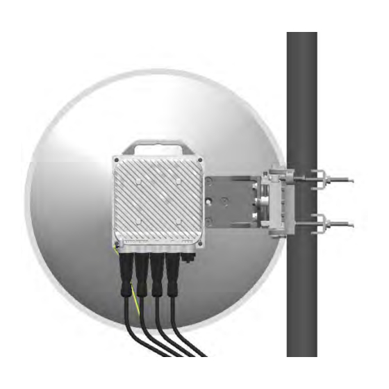
COMPOSITIONS 2.4.7 Antenna and its Mounting Brackets Figure 2-8 Antenna with its Mounting Brackets ANTENNA ANTENNA ATTACHMENT (example: onto Pole) MOUNTING BRACKET iPASOLINK EX Advanced: I GGS-000546-01E NSTALLATION... - Page 29 2-8/END COMPOSITIONS GGS-000546-01E iPASOLINK EX Advanced: I NSTALLATION...
- Page 30 3. UNPACK iPASOLINK EX/A Following show the methods of unpacking iPASOLINK EX/A. NOTE: Please keep the packing materials. If the equipment needs to be transported, 1. Unpack the container box by opening its top cover: CAUTION MARK iPASOLINK EX Advanced I GGS-000546-01E NSTALLATION...
- Page 31 2. Unbox the contents. The contents are boxed as shown below: TOP PAD POLYETHYLENE SHEET iPASOLINK EX/A BOTTOM PAD CONTAINER BOX 3. Remove the polyethylene sheet from iPASOLINK EX/A. 4. Inspect the iPASOLINK EX/A. This step ends the procedure. GGS-000546-01E iPASOLINK EX Advanced I NSTALLATION...
-
Page 32: Mount Ipasolink Ex/A
The other end of the Grounding terminal should be connected to the station earth point. For details, refer to 6. GROUND iPASOLINK EX/A section. Following show the methods of direct-mounting antenna. Depending on configuring system, the mounting methods differ. iPASOLINK EX Advanced:I GGS-000546-01E NSTALLATION... -
Page 33: Mount Ipasolink Ex/A For 1+0 System
V mark is found on the grip. Place this V mark on top. For the Vertical Polarization, either side to the pole is available to be mounted (no restrictions): (mounted on the right to the pole) (mounted on the left to the pole) Figure 4-1 V-Polarization and Position to Install GGS-000546-01E iPASOLINK EX Advanced:I NSTALLATION... -
Page 34: Polarization: Horizontal
H mark on bottom: (to mount the equipment on left to the pole) (to mount the equipment on right to the pole) Figure 4-2 H-Polarization and Position to Install iPASOLINK EX Advanced:I GGS-000546-01E NSTALLATION... -
Page 35: Secure Ipasolink Ex/A To Antenna Attachment
Attachment: NOTE: Tightening torque is 4.0 Nm ±10% POLE 50 ~ 115 mm; 2.0 ~ 4.5 inches) Figure 4-3 Mount iPASOLINK EX/A (example: H Mark is on Top) This step ends the procedure. GGS-000546-01E iPASOLINK EX Advanced:I NSTALLATION... -
Page 36: Mount Sfp Module
ATTENTION!! For the purpose of the use in iPASOLINK EX/A, it is recommended to use the SFPs that are designated and supplied by NEC. NEC will not guarantee the performances of iPASOLINK EX/A if other vendors’ SFP modules are installed. - Page 37 4-6/END MOUNT iPASOLINK EX/A This page is intentionally left blank. GGS-000546-01E iPASOLINK EX Advanced:I NSTALLATION...
-
Page 38: Connect Cables
To use this port as PoE, connect it to the power injector. To operate WebLCT , connect it to your PC (web browser must be installed). 4. Connect LAN Cables to P2 and P3 Ports, as necessary. iPASOLINK EX Advanced: I GGS-000546-01E NSTALLATION... -
Page 39: Connecting Terminals
➂ DCN (PoE) GbE; Power Supply by PoE (RJ-45); WebLCT or NMS Connecting Port ➃ SFP+ (GbE/10GbE) Port ➄ SFP+ (GbE/10GbE) Port ➅ USB Memory Interface ➆ Monitoring Port for RSL (Received Signal Level) GGS-000546-01E iPASOLINK EX Advanced: I NSTALLATION... -
Page 40: Grounding Cable
Following shows the location of Grounding terminal. Figure 5-2 Connect Grounding Cable example: mounted for V Polarization GROUNDING TERMINAL (M5) example: mounted for V Polarization 6. GROUND Detailed descriptions and routing methods are provided in the Section iPASOLINK EX/A. iPASOLINK EX Advanced: I GGS-000546-01E NSTALLATION... -
Page 41: Power Cable
Figure 5-3 Remove Protecting Cap on Power Port (2) The removed cap should be stored properly. 2. Connect the Power Cable (SELV): (1) Insert the Power Cable’s plug into the uncovered port. Figure 5-4 Connecting a Plug GGS-000546-01E iPASOLINK EX Advanced: I NSTALLATION... - Page 42 Figure 5-6 Place Plug Shell BARREL HOUSING BUSHING WITH RIB GLAND NUT (4) Push the Bushing into the barrel. Figure 5-7 Set Bushing into Barrel BARREL Check that the bushing is fully inserted within the barrel end. iPASOLINK EX Advanced: I GGS-000546-01E NSTALLATION...
- Page 43 CAUTION: In case using the thin cable, the Gland Nut may not stop and be secured at the appropriate position if tightening it by force. Ensure that the barrel end does not stick out of the gap at the Gland Nut end. This step ends the procedure. GGS-000546-01E iPASOLINK EX Advanced: I NSTALLATION...
-
Page 44: Lan Cables
Following shows the connecting method of the LAN Cable (Electric) and the waterproofing cap: Reference 1. Uncover the protected port. Waterproofing cap can be off by turning it counter- clockwise. Figure 5-9 Remove Waterproofing Cap from DCN (PoE) Port iPASOLINK EX Advanced: I GGS-000546-01E NSTALLATION... - Page 45 Check the shape of connector to insert the plug appropriately. 3. Place the housing over the RJ45 Connector, and engage it by turning it clockwise: Figure 5-11 Engage Housing no gap gasket is seen GGS-000546-01E iPASOLINK EX Advanced: I NSTALLATION...
- Page 46 CAUTION: In case using the thin cable, the Gland Nut may not stop and be secured at the appropriate position if tightening it by force. Ensure that the barrel end does not stick out of the gap at the Gland Nut end. This step ends the procedure. iPASOLINK EX Advanced: I GGS-000546-01E NSTALLATION...
-
Page 47: P2/P3 Port (Sfp+)
Following shows the connecting method of LAN Cable with SFP+ and waterproofing cap: Reference 1. Uncover the protected port. Waterproofing cap can be off by turning it counter- clockwise. Figure 5-15 Remove Waterproofing Cap GGS-000546-01E iPASOLINK EX Advanced: I NSTALLATION... - Page 48 2. Insert the LC Connectors into the SFP+ Port: Figure 5-16 Connect LAN Cable 3. Place the housing over the LC Connectors, and engage it by turning it clockwise:Slide the waterproofing cap toward the port fully. Figure 5-17 Engage Housing HOUSING iPASOLINK EX Advanced: I GGS-000546-01E NSTALLATION...
- Page 49 5. Tighten the Gland Nut at the barrel end level, and secure them using the torque wrench. Figure 5-19 Secure Gland Nut This step ends the procedure. Go to to end the Cable Connecting procedure. 5.6 Routing Cables GGS-000546-01E iPASOLINK EX Advanced: I NSTALLATION...
-
Page 50: Routing Cables
5-13 5.6 Routing Cables 5.6.1 Allowable Bending Radius of Cables Allowable bending radius of cables is 60 mm in diameter or greater. Figure 5-20 Allowable Bending Radius of Cables dia. 60 mm or greater iPASOLINK EX Advanced: I GGS-000546-01E NSTALLATION... -
Page 51: Secure Cables (For 1+0 System)
Secure the cables as shown below: 1. Tie cables. 2. Then secure tied cables onto the pole. Figure 5-21 Secure Cables (1+0 System) tie cables secure them onto pole This step ends the procedure. GGS-000546-01E iPASOLINK EX Advanced: I NSTALLATION... -
Page 52: Pin Assignment Of Connectors
5-15 5.7 Pin Assignment of Connectors Following shows the pin assignment of connectors used by iPASOLINK EX/A. 5.7.1 Summary 5.7.2 Power Port (SELV) 5.7.3 P1 Port 5.7.4 P2, P3 Port 5.7.4 P2, P3 Port iPASOLINK EX Advanced: I GGS-000546-01E NSTALLATION... -
Page 53: Power Port (Selv)
5.7.2 Power Port (SELV) Indication: DC –48V Connector Type: molex® MEGA-FIT4P Table 5-2 Pin Assignment of DC –48V Port (SELV) DC –48 V [4-Pin] PIN No. POWER PORT (SELV) ASSIGNMENT Positive Positive Negative Negative GGS-000546-01E iPASOLINK EX Advanced: I NSTALLATION... -
Page 54: P1 Port
DD+ / Positive V , Negative V DD / Positive V , Negative V NOTE: Use 4-pair shielded cable of CAT5e or higher. The cable should be shielded to keep operating in conformity with EMC standards. iPASOLINK EX Advanced: I GGS-000546-01E NSTALLATION... -
Page 55: P2, P3 Port
5-18 CONNECT CABLES 5.7.4 P2, P3 Port Indication: P2, P3 Port Type: SFP, SFP+ (LC Connector) Table 5-4 Pin Assignment of P2/P3 Port SFP/SFP++ PIN No. GbE/10GbE ASSIGNMENT GGS-000546-01E iPASOLINK EX Advanced: I NSTALLATION... -
Page 56: Assemble Cables
1. Cut the AWG10 cable to the appropriate length. 2. Strip approximately 7 mm of cable sheath from one end of each cable. 1~2 mm CABLE SHEATH (RING TERMINAL) 3. Slide the insulation sleeve onto the cable. INSULATION SLEEVE Slide iPASOLINK EX Advanced: I GGS-000546-01E NSTALLATION... - Page 57 4. Apply the Crimp Ring to the cable end, and fasten it using a crimping tool. crimp 1~2 mm (EXPOSED WIRE STRANDS) RING TERMINAL (side view) crimp 5. Slide insulation sleeve back to cover the root of crimp contact. INSULATION SLEEVE Slide back This step ends the procedure. GGS-000546-01E iPASOLINK EX Advanced: I NSTALLATION...
-
Page 58: Power Cable (2-Core Cable)
Connector Housing 17692-0104 Contact(s) 172063-0311 Cable AWG14 to 2-Core Double Insulated Cable, 5.86 to 10.00 mm in diameter: AWG16 Pin #1: Positive Pin #3: Negative Hand Crimping Tool 63825-7100 Waterproofing Plug —— Cover iPASOLINK EX Advanced: I GGS-000546-01E NSTALLATION... -
Page 59: Considering To Wear Waterproofing Plug Cover
Cover and Watertight Hose through prior to starting the procedure below . See 5.4 Power Cable also. Plug Cover Mechanism: 1. Disassemble the Waterproofing Plug Cover. 2. Put the cable into and through the parts. GGS-000546-01E iPASOLINK EX Advanced: I NSTALLATION... -
Page 60: Procedure
2. Remove the insulation to expose each conductor: 5.75 ±0.25 mm NOTE: Ensure not to damage the braided wire. • knife Tools • cutter • measuring tool, etc. 3. Set contact to each conductor. 4. Seal the crimp. iPASOLINK EX Advanced: I GGS-000546-01E NSTALLATION... - Page 61 Be sure to verify the orientation of completed connector when connecting it to the equipment. Assemble 2-Core Cable: POWER CONNECTOR HOUSING (REAR SIDE) Wear Waterproofing Plug Cover if Prepared: This step ends the procedure. GGS-000546-01E iPASOLINK EX Advanced: I NSTALLATION...
- Page 62 1. For grounding iPASOLINK EX/A, 5 mm square cable, which means more than 2.5 mm diameter cable, of AWG #10 with an appropriate crimping terminal should be used. Screwing torque should be within 2.7 ± 0.3N•m. iPASOLINK EX Advanced: I GGS-000546-01E NSTALLATION...
- Page 63 This type of wire is naked (not insulated), which is recommended. GROUND LEVEL NOTES: NEC recommends that the equipment should be connected to earth line as NEC’s standard installation. Earth Ground Point of tower GGS-000546-01E iPASOLINK EX Advanced: I NSTALLATION...
-
Page 64: Check Reception Level
Repeatedly turning the power on and off within a short interval may cause the equipment failure. 7.2 Check Reception Level Refer to for checking the reception levels. 8. ADJUST ANTENNA ANGLE iPASOLINK EX Advanced: I GGS-000546-01E NSTALLATION... -
Page 65: Shut Down Ipasolink Ex/A
7.3 Shut Down iPASOLINK EX/A 1. Powering off the power unit or power injector shuts down iPASOLINK EX/ WARNING: Disconnecting LAN Cable from DCN (PoE) Port while the equipment is powered on may cause the equipment failure. GGS-000546-01E iPASOLINK EX Advanced: I NSTALLATION... -
Page 66: Adjust Antenna Angle
(1) Launch WebLCT , and log in to the equipment. ➜ Radio (2) From the MENU pane, select Equipment Setup Configuration . (3) Click Setup tool button to display Step 1 Detailed Radio Configuration window. iPASOLINK EX Advanced: I GGS-000546-01E NSTALLATION... - Page 67 (4) At TX Power Control parameter, select MTPC if a different value is selected. Figure 8-2 Step 1 Detailed Equipment / Radio Setting Window 2. Repeat steps above at the opposing site. 3. Prepare to measure RX Level: GGS-000546-01E iPASOLINK EX Advanced: I NSTALLATION...
- Page 68 2. When the checks are done, put the waterproofing cap on to the RSL terminal to protect it. Figure 8-3 Example to Measure Levels for Fixing Angles RSL TERMINAL iPASOLINK EX/A DIGITAL MULTIMETER Following shows the relationship between RX INPUT LEVEL and RSL (V) . iPASOLINK EX Advanced: I GGS-000546-01E NSTALLATION...
- Page 69 ADJUST ANTENNA ANGLE Figure 8-4 RSL and RX Input Level RSL vs RX INPUT LEVEL (Typical) –80 –70 –60 –50 –40 –30 –20 RX INPUT LEVEL [dBm] GGS-000546-01E iPASOLINK EX Advanced: I NSTALLATION...
-
Page 70: Adjust Antenna Angle
RX Level Left/Right Adjustment Left/Right Adjustment Figure 8-7 Possible Attempts before Fine Adjustment Below Target Voltage CENTER CENTER CENTER (NO MAIN BEAM) (NO MAIN BEAM) CENTER (NO MAIN BEAM) (NO MAIN BEAM) Below Target Voltage iPASOLINK EX Advanced: I GGS-000546-01E NSTALLATION... - Page 71 (2) Rotate the bolt to turn the antenna to the left or right. (3) Adjust and specify parameters for control items using WebLCT at both opposing sites. (4) When the left/right angle is adjusted, secure the six bolts back in place. GGS-000546-01E iPASOLINK EX Advanced: I NSTALLATION...
- Page 72 5. Put the protective cap back in place on RSL terminal of each station. This terminal must be covered by the protective cap for waterproofing. 6. At each station, secure the Antenna by re-tightening bolts that have been loosen in Step 2. iPASOLINK EX Advanced: I GGS-000546-01E NSTALLATION...
-
Page 73: Safety Guideline For Microwave Radiation Hazard
40R Where P = Output Power (W), P’ = Output Power (dBm), G = Antenna Gain (dBi), (in condition of angle and range from antenna) R = Distance between human being and antenna (m) GGS-000546-01E iPASOLINK EX Advanced: I NSTALLATION... - Page 74 The safety distance that is obtained by the conditions above and is below the value defined by COUNCIL RECOMMENDATIN (1999/519/EC) of 1 mW/cm² is: Front Side of Antenna (X) 9.0 m Rear Side of Antenna (Y) 0.004 m = 4.0 mm iPASOLINK EX Advanced: I GGS-000546-01E NSTALLATION...
- Page 75 8-10/END ADJUST ANTENNA ANGLE This page is intentionally left blank. GGS-000546-01E iPASOLINK EX Advanced: I NSTALLATION...
- Page 76 GGS-000547-01E June 2016 iPASOLINK EX Advanced ETWORK AND YSTEM ROVISIONING NEC Corporation 7-1, Shiba 5-Chome, Minato-Ku, Tokyo 108-8001, Japan...
- Page 77 GGS-000547-01E © 2016 by NEC Corporation GGS-000547-01E Printed in Japan...
- Page 78 2.1.1 Import Software License Key ....... . . 2-1 iPASOLINK EX Advanced: S...
- Page 79 3.1.6.2 Session Management ........3-8 GGS-000547-01E iPASOLINK EX Advanced: S ETWORK AND...
- Page 80 3.11 SFTP ........... 3-50 GGS-000547-01E iPASOLINK EX Advanced: S ETWORK AND...
- Page 81 5.6.1.1 Add Entry......... . . 5-29 GGS-000547-01E iPASOLINK EX Advanced: S ETWORK AND...
- Page 82 7.3 ALM Mode Setting ......... 7-9 GGS-000547-01E iPASOLINK EX Advanced: S ETWORK AND...
- Page 83 8.6.4 LINK OAM Setting......... 8-83 GGS-000547-01E iPASOLINK EX Advanced: S ETWORK AND...
- Page 84 8.11.1.2 Modify Filter List ........8-171 GGS-000547-01E iPASOLINK EX Advanced: S ETWORK AND...
- Page 85 10.3.1 MODEM (1+0) ......... . . 10-10 GGS-000547-01E iPASOLINK EX Advanced: S ETWORK AND...
- Page 86 11.4.2.1 Add Shaper Group Counter......11-21 11.4.2.2 Delete Shaper Group Counter......11-23 GGS-000547-01E iPASOLINK EX Advanced: S ETWORK AND YSTEM...
- Page 87 – x/END – CONTENTS This page is intentionally left blank. GGS-000547-01E...
- Page 88 3. This document is provided on the assumption that the targeted users have skills and knowledge of restrictions and precautions to operate the equivalent equipment. Refer to the equipment manual for details. iPASOLINK EX Advanced: S GGS-000547-01E ETWORK AND YSTEM...
- Page 89 – ii/END – DOCUMENT WARRANTY This page is intentionally left blank. GGS-000547-01E iPASOLINK EX Advanced: S ETWORK AND YSTEM ROVISIONING...
- Page 90 Press Enter key. its first letter. 1.2 LCT Communication Interface 1.2.1 Communications iPASOLINK EX Advanced (hereinafter iPASOLINK EX/A) provides WebLCT the Local Craft Terminal (LCT) that is a convenient tool to install and maintain the equipment. uses the GUI method on WEB browser. In addition, this tool WebLCT enables a remote connection.
- Page 91 2 GB or greater 40 GB or greater 40 GB or greater Display Color LCD (1024 × 768) Color LCD (1024 × 768) LAN Port 10/100BASE-T(X) 10/100BASE-T(X) ——— ——— USB Port GGS-000547-01E iPASOLINK EX Advanced: S ETWORK AND YSTEM ROVISIONING...
- Page 92 WebLCT. Using this function may affect the appearance of WebLCT windows. 1.5 Operating System Environment Check if your PC satisfies the conditions below: Internet Explorer is installed TCP/IP Protocol is properly set. iPASOLINK EX Advanced: S GGS-000547-01E ETWORK AND YSTEM ROVISIONING...
- Page 93 Tools Internet . Following example is selecting on the menu bar. Options Tools Figure 1-2 Internet Explorer — Select Internet Options window appears. Internet Options GGS-000547-01E iPASOLINK EX Advanced: S ETWORK AND YSTEM ROVISIONING...
- Page 94 4. The option window appears. Select Tabbed Browsing Settings Always open , then click the button. pop-ups in a new tab Figure 1-4 Tabbed Browsing Settings Option Window Proceed to Procedure 1-2 iPASOLINK EX Advanced: S GGS-000547-01E ETWORK AND YSTEM ROVISIONING...
- Page 95 Select Security Settings — Internet Zone Enable — option. Downloads Automatic prompting for file downloads Figure 1-6 Internet Options — Security Settings — Internet Zone 3. Click the button. GGS-000547-01E iPASOLINK EX Advanced: S ETWORK AND YSTEM ROVISIONING...
- Page 96 Tools Options Figure 1-7 Firefox — Tools Menu 3. The Options window appears. Select Always ask me where to save files then click the button. Figure 1-8 Options — General iPASOLINK EX Advanced: S GGS-000547-01E ETWORK AND YSTEM ROVISIONING...
- Page 97 2. Launch the Internet Explorer® newly, and go to the web site by following URL: http://support.microsoft.com/kb/175500 Figure 1-10 Error Message (Example used here is English Version. Language used differs according to where you are.) GGS-000547-01E iPASOLINK EX Advanced: S ETWORK AND YSTEM ROVISIONING...
- Page 98 Fix it tool button dialog box appears. Click the Security Warning button in the dialog box, and follow the steps in the wizard: Fix it Figure 1-12 Security Warning Dialog Box iPASOLINK EX Advanced: S GGS-000547-01E ETWORK AND YSTEM ROVISIONING...
- Page 99 Don’t ask me again Figure 1-14 Request Action Don’t ask me again check box Continue button 2. Then click the button. Continue This warning message will not appear again. GGS-000547-01E iPASOLINK EX Advanced: S ETWORK AND YSTEM ROVISIONING...
- Page 100 Address /weblct/ below: http://172.17.254.253/weblct/ Example: Figure 1-15 Launch WebLCT 5. The Login window for WebLCT appears. Enter a user name and his/her password into fields: User Name Password iPASOLINK EX Advanced: S GGS-000547-01E ETWORK AND YSTEM ROVISIONING...
- Page 101 (The System indicator disappears in a while without clicking the button if you Status wait.) Figure 1-17 System Status Indicator The main window for appears: WebLCT GGS-000547-01E iPASOLINK EX Advanced: S ETWORK AND YSTEM ROVISIONING...
- Page 102 OPERATE WebLCT 1-13 Figure 1-18 WebLCT Main Window iPASOLINK EX Advanced: S GGS-000547-01E ETWORK AND YSTEM ROVISIONING...
- Page 103 1.8.3 Exit WebLCT Following are the methods to exit WebLCT: Select from menu bar. File (F) Close (X) Internet Explorer Click button in the upper right of Internet Explorer GGS-000547-01E iPASOLINK EX Advanced: S ETWORK AND YSTEM ROVISIONING...
- Page 104 (2) Logged-In User Name [Login User] This field indicates a user name that is currently logged in. (3) Refresh button Click button to manually update the current status displayed in the Refresh WebLCT main window. iPASOLINK EX Advanced: S GGS-000547-01E ETWORK AND YSTEM ROVISIONING...
- Page 105 This item is to configure and set up the network environment. This item also provides the User Account management as well. (d) Provisioning This item is to configure the detailed settings of the Equipment. GGS-000547-01E iPASOLINK EX Advanced: S ETWORK AND YSTEM ROVISIONING...
- Page 106 Inventory license. (k) S/W License Setup This menu is used to import the license keys. (11) Detailed Information This part shows detailed information or a setting procedure under each menu. iPASOLINK EX Advanced: S GGS-000547-01E ETWORK AND YSTEM ROVISIONING...
- Page 107 1-18/END OPERATE WebLCT This page is intentionally left blank. GGS-000547-01E iPASOLINK EX Advanced: S ETWORK AND YSTEM ROVISIONING...
- Page 108 S/W License Setup . The window appears. Import License key Import License key 3. Click the Setup tool button. Figure 2-1 S/W License Setup — Import License key Window Setup tool button iPASOLINK EX Advanced: S GGS-000547-01E ETWORK AND YSTEM ROVISIONING...
- Page 109 Figure 2-3 Choose File to Upload Option Window 5. Import License key option window displays the selected file name. Confirm the file name, then click the button to proceed. Figure 2-4 Import License key Option Window (selected) GGS-000547-01E iPASOLINK EX Advanced: S ETWORK AND YSTEM ROVISIONING...
- Page 110 LICENSE AND USER ACCOUNT 6. When the importing process ends, the Import License key window updates the information. Figure 2-5 Import License key Dialog Box This step ends the procedure. iPASOLINK EX Advanced: S GGS-000547-01E ETWORK AND YSTEM ROVISIONING...
-
Page 111: User Management
HTTPS SNMP Access Level ✔ ✔ ✔ ✔ ✔ ✔ OPERATOR Unchangeable Operator ✔ ✔ ✔ ✔ ✔ ✔ CONFIG Unchangeable Config ✔ ✔ ✔ ✔ ✔ ✔ ADMIN Unchangeable Admin GGS-000547-01E iPASOLINK EX Advanced: S ETWORK AND YSTEM ROVISIONING... -
Page 112: User Access Levels
Login User List — — Setting User Authentication — — Configuration User Account Management — — User Group Profile — — Configuration Security Management Service Status Setting — — RADIUS Setting — — iPASOLINK EX Advanced: S GGS-000547-01E ETWORK AND YSTEM ROVISIONING... - Page 113 PTP Mode Setting PTP Domain Setting Alarm/AIS Setting Correlation Setting Alarm Severity Setting BER Threshold Setting — PMON/RMON Setting PMON Threshold Setting RMON Threshold Setting Other Threshold Setting VLAN Counter Setting GGS-000547-01E iPASOLINK EX Advanced: S ETWORK AND YSTEM ROVISIONING...
- Page 114 Update (Storage -> NE) Utility — — Program ROM Switching — — USB Memory Utility Log Clear Function — — Shipment — — — Inventory Equipment Inventory Information S/W License Information iPASOLINK EX Advanced: S GGS-000547-01E ETWORK AND YSTEM ROVISIONING...
-
Page 115: Default User Account
Admin In addition to the tasks available for a Config user, 12345678 ADMIN Admin user is able to operate database management, file management, user management and time adjustment for M-Plane control. GGS-000547-01E iPASOLINK EX Advanced: S ETWORK AND YSTEM ROVISIONING... -
Page 116: User Account
User Account Management delete the registered user accounts. User Group Profile Configuration is used to register new , and to User Group Profile Configuration User Groups modify/delete the registered User Groups iPASOLINK EX Advanced: S GGS-000547-01E ETWORK AND YSTEM ROVISIONING... -
Page 117: Login User List
Login User List Login User List appears. Figure 2-6 Login User List This step ends the procedure. To specify the maximum number of accessing users, go to 2.2.4.2 Login User Control GGS-000547-01E iPASOLINK EX Advanced: S ETWORK AND YSTEM ROVISIONING... -
Page 118: Login User Control
Table 2-5 Login User Control Setting Parameters Parameter Value Description Total Number of Admin/ 1 to 5 Limits the maximum number of Admin and Config Level Accounts Config level users to log in. iPASOLINK EX Advanced: S GGS-000547-01E ETWORK AND YSTEM ROVISIONING... - Page 119 3. Information dialog box appears. Click the OK button to proceed. Figure 2-9 Information Dialog Box 4. Login User List window updates the information. Figure 2-10 Login User List Window This step ends the procedure. GGS-000547-01E iPASOLINK EX Advanced: S ETWORK AND YSTEM ROVISIONING...
-
Page 120: User Authentication Configuration
User Account / Security Setting User Authentication . The window appears. Configuration User Authentication Configuration 3. Click the link. Authentication Setting Figure 2-11 User Authentication Configuration Window click the link iPASOLINK EX Advanced: S GGS-000547-01E ETWORK AND YSTEM ROVISIONING... - Page 121 Disable Disables the account locking (Login Protection) that is the internal authentication function using the registered account and their passwords. Information dialog box appears. Click the button to proceed. GGS-000547-01E iPASOLINK EX Advanced: S ETWORK AND YSTEM ROVISIONING...
- Page 122 Verify the displayed information. Figure 2-14 User Authentication Configuration Window This step ends the procedure. To assign privilege IDs and Group Names, go to 2.2.4.4 Privilege ID and Group Name iPASOLINK EX Advanced: S GGS-000547-01E ETWORK AND YSTEM ROVISIONING...
-
Page 123: Privilege Id And Group Name
Figure 2-15 User Authentication Configuration Window Privilege ID numbers option window for the selected ID number appears. Select the Privilege ID method to assign, then click the button. Figure 2-16 Privilege ID Option Window GGS-000547-01E iPASOLINK EX Advanced: S ETWORK AND YSTEM ROVISIONING... - Page 124 Information Figure 2-17 Information Dialog Box 4. The window updates the information. User Authentication Configuration Verify the displayed information. Figure 2-18 User Authentication Configuration Window This step ends the procedure. iPASOLINK EX Advanced: S GGS-000547-01E ETWORK AND YSTEM ROVISIONING...
-
Page 125: User Account Management
This function is used to modify the information of registered user accounts including their password and User Group Delete User Account This function is used to remove registered user accounts. GGS-000547-01E iPASOLINK EX Advanced: S ETWORK AND YSTEM ROVISIONING... - Page 126 User Account / Security Setting User Account . The window appears. Management User Account Management 3. Click tool button. Add User Figure 2-19 User Account Management Window Add User button option window appears. User Setting iPASOLINK EX Advanced: S GGS-000547-01E ETWORK AND YSTEM ROVISIONING...
- Page 127 AuthPriv Auth Algorithm Priv Algorithm Click radio buttons to select algorithm types, and enter Auth Key and Priv Key. (a) Setting Authentication Algorithm (b) Setting Privacy Algorithm below. GGS-000547-01E iPASOLINK EX Advanced: S ETWORK AND YSTEM ROVISIONING...
- Page 128 Figure 2-22 Set Auth Key ➃ ➂ ➀ ➁ Verify the selection and entry. To set Priv Algorithm, go to below. (b) Setting Privacy Algorithm To complete the procedure, go to Step 5. iPASOLINK EX Advanced: S GGS-000547-01E ETWORK AND YSTEM ROVISIONING...
- Page 129 Verify the selection and entry, then go to Step 5. 5. Click the button of the User Setting option window. The Information dialog box appears. 6. Click the button to proceed. Figure 2-24 Information Dialog Box GGS-000547-01E iPASOLINK EX Advanced: S ETWORK AND YSTEM ROVISIONING...
- Page 130 The block size is 128 bits, and the length of the key is 128/192/256 bits. Priv Key Valid value: Eight to 16 digits. To enter the Privacy Key, click Set Priv Key (read only) button on the tool bar. iPASOLINK EX Advanced: S GGS-000547-01E ETWORK AND YSTEM ROVISIONING...
- Page 131 Set Password button on the tool bar to open the Password option window, enter the password within eight to 31 characters long, and click the button of the option window. Set Password GGS-000547-01E iPASOLINK EX Advanced: S ETWORK AND YSTEM ROVISIONING...
- Page 132 To modify the Group Name, select an appropriate Group Name from the Group Name drop-down list. See for User Groups. Table 2-2 User Group Profile Figure 2-28 Set Password Option Window 5. When completed, click button of the User Setting option window. iPASOLINK EX Advanced: S GGS-000547-01E ETWORK AND YSTEM ROVISIONING...
- Page 133 LICENSE AND USER ACCOUNT Figure 2-29 User Setting Option Window 6. The dialog box appears. Click the Information button to proceed. Figure 2-30 Information Dialog Box window updates the information. User Account Management GGS-000547-01E iPASOLINK EX Advanced: S ETWORK AND YSTEM ROVISIONING...
- Page 134 LICENSE AND USER ACCOUNT 2-27 7. Confirm the modified user account information. Figure 2-31 User Account Management Window This step ends the procedure. iPASOLINK EX Advanced: S GGS-000547-01E ETWORK AND YSTEM ROVISIONING...
- Page 135 4. The option window appears. From User Setting User Name drop-down list, select a user account to be removed, and click the button. Figure 2-33 User Setting (Delete) Option Window GGS-000547-01E iPASOLINK EX Advanced: S ETWORK AND YSTEM ROVISIONING...
- Page 136 Figure 2-35 Information Dialog Box 7. The window updates the information. Confirm that User Account Management the selected user account has been removed. Figure 2-36 User Account Management Window This step ends the procedure. iPASOLINK EX Advanced: S GGS-000547-01E ETWORK AND YSTEM ROVISIONING...
-
Page 137: User Group Profile Configuration
Modify User Group Profile This operation modifies the Access Level and Protocol of the registered User Group Profile. Delete User Group Profile This operation deletes a registered User Group Profile. GGS-000547-01E iPASOLINK EX Advanced: S ETWORK AND YSTEM ROVISIONING... - Page 138 3. The window appears. Click tool User Group Profile Configuration Add Group button on the tool bar. Figure 2-37 User Group Profile Configuration Window Add Group button option window appears. Group Setting iPASOLINK EX Advanced: S GGS-000547-01E ETWORK AND YSTEM ROVISIONING...
- Page 139 Select to use SNMP protocol for accessing NEs. Deny Not to use SNMP protocol for accessing NEs. Access Level Admin Table 2-3 User Access Specifies the user access level. See Privilege Levels for each level’s description. Config Operator GGS-000547-01E iPASOLINK EX Advanced: S ETWORK AND YSTEM ROVISIONING...
- Page 140 User Group Profile Configuration Confirm that the information of newly added User Group Profile is displayed. Figure 2-40 User Group Profile Configuration Window This step ends the procedure iPASOLINK EX Advanced: S GGS-000547-01E ETWORK AND YSTEM ROVISIONING...
- Page 141 User Group Profile Configuration . The User Group Profile Configuration window appears. 3. Click on a target Group Name. Figure 2-41 User Group Profile Configuration Window click option window appears. Group Setting GGS-000547-01E iPASOLINK EX Advanced: S ETWORK AND YSTEM ROVISIONING...
- Page 142 Access Level 5. Click the button when completed. The dialog box appears. Information 6. Click the button to proceed. Figure 2-43 Information Dialog Box window updates the information. User Group Profile Configuration iPASOLINK EX Advanced: S GGS-000547-01E ETWORK AND YSTEM ROVISIONING...
- Page 143 2-36 LICENSE AND USER ACCOUNT 7. Confirm the displayed Group Profile information. Figure 2-44 User Group Profile Configuration Window This step ends the procedure. GGS-000547-01E iPASOLINK EX Advanced: S ETWORK AND YSTEM ROVISIONING...
- Page 144 Delete Group button 4. The option window appears. Select a target Group Name to be Group Setting removed from the drop-down list, and click the button. Figure 2-46 Group Setting (Delete) Option Window iPASOLINK EX Advanced: S GGS-000547-01E ETWORK AND YSTEM ROVISIONING...
- Page 145 7. The window updates the information. User Group Profile Configuration Confirm that the target group name has been removed. Figure 2-49 User Group Profile Configuration Window This step ends the procedure. GGS-000547-01E iPASOLINK EX Advanced: S ETWORK AND YSTEM ROVISIONING...
-
Page 146: Security Management
Requests the subsequent instance value of specified instance value in the list. GetResponse Responds to the corresponding GetRequest and Set Request. SetRequest Sets the specified instance value. Trap Informs the change of state and troubles (SNMPv1-Trap). iPASOLINK EX Advanced: S GGS-000547-01E ETWORK AND YSTEM ROVISIONING... -
Page 147: Send Trap
Network Management Framework SMIv2 RFC 2578 Structure of Management Information Version 2 (SMIv2) RFC 2579 Textual Conventions for SMIv2 RFC 2580 Conformance Statements for SMIv2 iPASOLINK enables SNMPv2c to support the following functions: GGS-000547-01E iPASOLINK EX Advanced: S ETWORK AND YSTEM ROVISIONING... -
Page 148: Get/Set Of Mib
NEs on an IP network, and is the newest version of SNMP. The differences between SNMPv1/v2c and v3 are that the user authentication, ciphered communication, and the change-packet format are enhanced, conforming to the following RFCs for SMIv2 that define SNMPv3, SNMPv2c: iPASOLINK EX Advanced: S GGS-000547-01E ETWORK AND YSTEM... - Page 149 Network Management Framework SMIv2 RFC 2578 Structure of Management Information Version 2 (SMIv2) RFC 2579 Textual Conventions for SMIv2 RFC 2580 Conformance Statements for SMIv2 iPASOLINK provides SNMPv3 to support the following function: GGS-000547-01E iPASOLINK EX Advanced: S ETWORK AND YSTEM ROVISIONING...
-
Page 150: Get/Set Of Mib
DES and AES. For the ciphered communication, a password must be set when registering users. User can also specify an SNMP Engine ID for each NE, which should be 16-byte long and unique within the network. iPASOLINK EX Advanced: S GGS-000547-01E ETWORK AND YSTEM... -
Page 151: Ntp
When the unicast mode is selected on the NTP Server, Server will respond the current time information to the Client. When the multicast mode is selected, the Server will broadcast the current time information of its own periodically. GGS-000547-01E iPASOLINK EX Advanced: S ETWORK AND YSTEM ROVISIONING... -
Page 152: Ftp
If no command is issued by the Client for ninety seconds, the current TCP session will be disconnected automatically. 3.1.5.3 User Authentication Function iPASOLINK supports the internal authentication only. iPASOLINK EX Advanced: S GGS-000547-01E ETWORK AND YSTEM ROVISIONING... -
Page 153: Sshv2
An unauthorized user is not accepted. The default port number of SSHv2 Service is 22, which cannot be changed by WebLCT. 3.1.6.3 User Authentication Function iPASOLINK supports the internal authentication only. GGS-000547-01E iPASOLINK EX Advanced: S ETWORK AND YSTEM ROVISIONING... -
Page 154: Sftp
Changing the SSH Connection Port # requires special attention since the Port # of SSH Connection and that of SFTP connection are the same (cannot change either one alone). 3.1.7.4 User Authentication Function iPASOLINK supports the internal authentication only. iPASOLINK EX Advanced: S GGS-000547-01E ETWORK AND YSTEM ROVISIONING... -
Page 155: Http
The default port number of HTTP Service is 80, which can be changed using WebLCT. 3.1.8.3 User Authentication Function iPASOLINK supports the following two types of authentications: External RADIUS Server with internal authentication. Internal authentication only. GGS-000547-01E iPASOLINK EX Advanced: S ETWORK AND YSTEM ROVISIONING... -
Page 156: Https
443 by default, which can be changed by WebLCT/SNMP. 3.1.9.3 User Authentication Function iPASOLINK supports the following two types of authentications: External RADIUS Server with internal authentication. Internal authentication only. iPASOLINK EX Advanced: S GGS-000547-01E ETWORK AND YSTEM ROVISIONING... -
Page 157: Service Status Setting
, and its MENU Network Management Setting submenu to select . The Security Management Service Status Setting Service Status Setting window appears: Figure 3-1 Service Status Setting Window (1/2) GGS-000547-01E iPASOLINK EX Advanced: S ETWORK AND YSTEM ROVISIONING... - Page 158 SECURITY MANAGEMENT 3-13 Figure 3-2 Service Status Setting Window (2/2) iPASOLINK EX Advanced: S GGS-000547-01E ETWORK AND YSTEM ROVISIONING...
- Page 159 3-14 SECURITY MANAGEMENT Figure 3-3 Service Status Indication Table 3-12 Service Status Indication Status Description Running Protocol/Service is enabled. Stopped Protocol/Service is disabled. This step ends the procedure. GGS-000547-01E iPASOLINK EX Advanced: S ETWORK AND YSTEM ROVISIONING...
-
Page 160: Snmp
. The Security Management Service Status Setting Service Status Setting window appears. 3. Click the link: SNMP Figure 3-4 Service Status Setting Window (SNMP) SNMP Setting option window appears. SNMP iPASOLINK EX Advanced: S GGS-000547-01E ETWORK AND YSTEM ROVISIONING... - Page 161 UDP Port Number(s) is/are changed. 5. When completed, click the button. dialog box appears. Information 6. Click the button to proceed. Figure 3-6 Information Dialog Box window updates the information. Service Status Setting GGS-000547-01E iPASOLINK EX Advanced: S ETWORK AND YSTEM ROVISIONING...
- Page 162 SECURITY MANAGEMENT 3-17 7. Confirm the displayed SNMP information. Figure 3-7 Service Status Setting Window This step ends the procedure. iPASOLINK EX Advanced: S GGS-000547-01E ETWORK AND YSTEM ROVISIONING...
-
Page 163: Snmp Community
. The Security Management Service Status Setting window appears. Service Status Setting 3. Click a Community No. to add. Figure 3-8 Service Status Setting Window (SNMP Community) SNMP Community numbers GGS-000547-01E iPASOLINK EX Advanced: S ETWORK AND YSTEM ROVISIONING... - Page 164 Specifies the valid IP address or network address of the SNMP Manager(s). Subnet Mask x.x.x.x Specify the Subnet Mask of SNMP Manager(s). 5. Click the button when completed. The dialog box appears. Information iPASOLINK EX Advanced: S GGS-000547-01E ETWORK AND YSTEM ROVISIONING...
- Page 165 7. The window updates the information. Confirm that the Service Status Setting newly added SNMP Community information is displayed. Figure 3-11 Service Status Setting Window (SNMP Community) This step ends the procedure. GGS-000547-01E iPASOLINK EX Advanced: S ETWORK AND YSTEM ROVISIONING...
-
Page 166: Delete Snmp Community
4. The option window appears. Select an SNMP Delete SNMP Community Community No. from the drop-down list, and click the button. Figure 3-13 Delete SNMP Communication Option Window dialog box appears. Confirmation iPASOLINK EX Advanced: S GGS-000547-01E ETWORK AND YSTEM ROVISIONING... - Page 167 7. The window updates the information. Confirm that the Service Status Setting selected SNMP Community information has been removed. Figure 3-16 Service Status Setting Window (SNMP Community) This step ends the procedure. GGS-000547-01E iPASOLINK EX Advanced: S ETWORK AND YSTEM ROVISIONING...
-
Page 168: Snmp Trap Entry
4. Click SNMP Trap Entry No. of the field. SNMP Trap Entry Figure 3-17 Service Status Setting Window (SNMP Trap Entry) SNMP Trap Entry No. option window appears. SNMP Trap Entry iPASOLINK EX Advanced: S GGS-000547-01E ETWORK AND YSTEM ROVISIONING... - Page 169 3-24 SECURITY MANAGEMENT 5. Specify the appropriate value for each parameter: Figure 3-18 SNMP Trap Entry Option Window GGS-000547-01E iPASOLINK EX Advanced: S ETWORK AND YSTEM ROVISIONING...
- Page 170 Valid value: Eight to 16 digits. To enter the Privacy Key, click Set (read only) Priv Key button on the tool bar. NOTE: are the only required parameters to set for Security Level SNMP Engine ID registering SNMPv3 (inform). iPASOLINK EX Advanced: S GGS-000547-01E ETWORK AND YSTEM ROVISIONING...
- Page 171 Confirm that the Service Status Setting newly added SNMP Trap Entry information is displayed. Figure 3-20 Service Status Setting Window (SNMP Trap Entry) This step ends the procedure. GGS-000547-01E iPASOLINK EX Advanced: S ETWORK AND YSTEM ROVISIONING...
-
Page 172: Delete Snmp Trap Entry
From the drop-down list, Delete SNMP Trap Entry select the No. of SNMP Trap Entry to be removed, and click the button. Figure 3-22 Delete SNMP Trap Entry Option Window iPASOLINK EX Advanced: S GGS-000547-01E ETWORK AND YSTEM ROVISIONING... - Page 173 Confirm that the Service Status Setting selected SNMP Trap Entry information has been removed from the display. Figure 3-25 Service Status Setting Window (SNMP Trap Entry) This step ends the procedure. GGS-000547-01E iPASOLINK EX Advanced: S ETWORK AND YSTEM ROVISIONING...
-
Page 174: Ntp
Service Status Setting window appears. 3. Scroll down the main window until the NTP option appears. link. 4. Click the Figure 3-26 Service Status Setting Window (NTP) box appears. NTP Setting iPASOLINK EX Advanced: S GGS-000547-01E ETWORK AND YSTEM ROVISIONING... - Page 175 Bridge01 to Bridege06 Select a port to output the Multicast Time information. This parameter is enabled when NTP Server Mode selects Multicast. Multicast Interval 16 to 131072s Select Multicast Interval. [unit: second] GGS-000547-01E iPASOLINK EX Advanced: S ETWORK AND YSTEM ROVISIONING...
- Page 176 Confirm the Service Status Setting displayed NTP configuration. Figure 3-29 Service Status Setting Window (Service Status) Figure 3-30 Service Status Setting Window (NTP) This step ends the procedure. iPASOLINK EX Advanced: S GGS-000547-01E ETWORK AND YSTEM ROVISIONING...
-
Page 177: Ntp Client Status
3-32 SECURITY MANAGEMENT 3.6.2 NTP Client Status Clicking the NTP Client Status link opens the NTP Client Status window: Figure 3-31 NTP Client Status Window GGS-000547-01E iPASOLINK EX Advanced: S ETWORK AND YSTEM ROVISIONING... -
Page 178: Ntp Server Address
3. Click the No. of the target NTP Server listed in NTP Server Address Figure 3-32 Service Status Setting Window (NTP Server Address) No. of NTP Servers option window appears. NTP Server Address Setting iPASOLINK EX Advanced: S GGS-000547-01E ETWORK AND YSTEM ROVISIONING... - Page 179 5. Click the button when completed. dialog box appears. Information 6. Click the button to proceed. Figure 3-34 Information Dialog Box window updates the information. Service Status Setting GGS-000547-01E iPASOLINK EX Advanced: S ETWORK AND YSTEM ROVISIONING...
- Page 180 SECURITY MANAGEMENT 3-35 7. Confirm that the newly added NTP Server Address information is displayed. Figure 3-35 Service Status Setting Window (NTP Server Address) This step ends the procedure. iPASOLINK EX Advanced: S GGS-000547-01E ETWORK AND YSTEM ROVISIONING...
-
Page 181: Delete Ntp Server Address
Clear NTP Server 4. From drop-down list, select the number of target NTP Server Address, and the click the button: Figure 3-37 NTP Server Address Setting Option Window dialog box appears. Confirmation GGS-000547-01E iPASOLINK EX Advanced: S ETWORK AND YSTEM ROVISIONING... - Page 182 Confirm that the Service Status Setting selected NTP Server Address information has been removed. Figure 3-40 Service Status Setting Window (NTP Server Address) This step ends the procedure. iPASOLINK EX Advanced: S GGS-000547-01E ETWORK AND YSTEM ROVISIONING...
-
Page 183: Ntp Auth Key Setting
NTP Auth Key Setting 4. Click the number of Auth Key Index link. Figure 3-41 Service Status Setting Window (NTP Auth Key Setting) Auth Key Index NTP Auth Key Setting (Modify) option window appears. GGS-000547-01E iPASOLINK EX Advanced: S ETWORK AND YSTEM ROVISIONING... - Page 184 Password Setting option window. Specify the password, then click the OK button: Auth Key Trust Trusted Trusts the configured Authentication Key. Not Trusted Not to trust the configured Authentication Key. iPASOLINK EX Advanced: S GGS-000547-01E ETWORK AND YSTEM ROVISIONING...
- Page 185 8. The Service Status Setting window updates the information. Confirm the displayed NTP Auth Key Setting information. Figure 3-45 Service Status Setting (NTP Auth Key Setting) This step ends the procedure. GGS-000547-01E iPASOLINK EX Advanced: S ETWORK AND YSTEM ROVISIONING...
-
Page 186: Remove Registered Ntp Authentication Key
4. Clear NTP Auth Key option window appears. Select an index number of Authentication Key to be removed. Figure 3-47 Clear NTP Auth Key Option Window 5. Confirmation dialog box appears. Click the OK button to proceed. iPASOLINK EX Advanced: S GGS-000547-01E ETWORK AND YSTEM... - Page 187 7. The Service Status Setting window updates the information. Confirm that the Auth Key registration of selected index number is removed. Figure 3-50 Service Status Setting Window (NTP Auth Key Setting) This step ends the procedure. GGS-000547-01E iPASOLINK EX Advanced: S ETWORK AND YSTEM ROVISIONING...
-
Page 188: Ftp
Service Status Setting 3. Scroll down the main window until FTP option appears. 4. Click the link. Figure 3-51 Service Status Setting Window (FTP) option window appears. FTP Setting iPASOLINK EX Advanced: S GGS-000547-01E ETWORK AND YSTEM ROVISIONING... - Page 189 FTP Server will not disconnect a session whether or not a session has an operation. 6. Click the button when completed. Warning dialog box appears. Click the button to proceed. Figure 3-53 Warning Dialog Box GGS-000547-01E iPASOLINK EX Advanced: S ETWORK AND YSTEM ROVISIONING...
- Page 190 Click the button. Information Figure 3-54 Information Dialog Box window updates the information. Service Status Setting 9. Confirm the displayed FTP information: Figure 3-55 Service Status Setting Window (Service Status) iPASOLINK EX Advanced: S GGS-000547-01E ETWORK AND YSTEM ROVISIONING...
- Page 191 3-46 SECURITY MANAGEMENT Figure 3-56 Service Status Setting Window (FTP) This step ends the procedure. GGS-000547-01E iPASOLINK EX Advanced: S ETWORK AND YSTEM ROVISIONING...
-
Page 192: Sshv2
Service Status Setting 3. Scroll down the main window until SSHv2 option appears. 4. Click the link. SSHv2 Figure 3-57 Service Status Setting Window (SSHv2, SFTP) click option window appears. SSHv2/SFTP Setting iPASOLINK EX Advanced: S GGS-000547-01E ETWORK AND YSTEM ROVISIONING... - Page 193 Always Enable Auto Disable Enable Disable dialog box appears. Click the button. Information Figure 3-59 Information Dialog Box window updates the information. Service Status Setting 7. Verify the displayed SFTP information. GGS-000547-01E iPASOLINK EX Advanced: S ETWORK AND YSTEM ROVISIONING...
- Page 194 SECURITY MANAGEMENT 3-49 Figure 3-60 Service State Setting Window (Service Status) Figure 3-61 Service State Setting Window (SSHv2) This step ends the procedure. iPASOLINK EX Advanced: S GGS-000547-01E ETWORK AND YSTEM ROVISIONING...
-
Page 195: Sftp
Service Status Setting 3. Scroll down the main window until SFTP option appears. 4. Click the SFTP link. Figure 3-62 Service Status Setting Window (SFTP) click option window appears. SSHv2/SFTP Setting GGS-000547-01E iPASOLINK EX Advanced: S ETWORK AND YSTEM ROVISIONING... - Page 196 SFTP Server will not disconnect a session if a session has no operation. Information dialog box appears. Click the button. Figure 3-64 Information Dialog Box window updates the information. Service Status Setting iPASOLINK EX Advanced: S GGS-000547-01E ETWORK AND YSTEM ROVISIONING...
- Page 197 3-52 SECURITY MANAGEMENT 7. Verify the displayed SFTP information. Figure 3-65 Service State Setting Window (Service Status) Figure 3-66 Service State Setting Window (SFTP) This step ends the procedure. GGS-000547-01E iPASOLINK EX Advanced: S ETWORK AND YSTEM ROVISIONING...
-
Page 198: Http
Service Status Setting 3. Scroll down the main window until HTTP option appears. 4. Click the link. HTTP Figure 3-67 Service Status Setting Window (HTTP) HTTP option window appears. HTTP/HTTPS Setting iPASOLINK EX Advanced: S GGS-000547-01E ETWORK AND YSTEM ROVISIONING... - Page 199 Click the button to proceed. Warning Figure 3-69 Waring Dialog Box dialog box appears. Click the button. Information Figure 3-70 Information Dialog Box 9. The window updates the information. Service Status Setting GGS-000547-01E iPASOLINK EX Advanced: S ETWORK AND YSTEM ROVISIONING...
- Page 200 SECURITY MANAGEMENT 3-55 10. Confirm the displayed HTTP information: Figure 3-71 Service Status Setting Window (Service Status) Figure 3-72 Service Status Setting Window (HTTP) This step ends the procedure. iPASOLINK EX Advanced: S GGS-000547-01E ETWORK AND YSTEM ROVISIONING...
-
Page 201: Https
Service Status Setting 3. Scroll the main window to display HTTPS appears. 4. Click the link. HTTPS Figure 3-73 Service Status Setting Window (HTTPS) HTTPS option window appears. HTTPS Setting GGS-000547-01E iPASOLINK EX Advanced: S ETWORK AND YSTEM ROVISIONING... - Page 202 6. Click the button when completed. dialog box appears. Click the button to proceed. Warning Figure 3-75 Waring Dialog Box dialog box appears. Click the button. Information Figure 3-76 Information Dialog Box iPASOLINK EX Advanced: S GGS-000547-01E ETWORK AND YSTEM ROVISIONING...
- Page 203 Service Status Setting 10. Confirm the displayed HTTPS information: Figure 3-77 Service Status Setting Window (Service Status) Figure 3-78 Service Status Setting Window (HTTPS) This step ends the procedure. GGS-000547-01E iPASOLINK EX Advanced: S ETWORK AND YSTEM ROVISIONING...
-
Page 204: Radius Setting
RADIUS Setting Specifies the method of authentications at login. RADIUS Server Setting Specifies the setting values to User Service Server. Clear RADIUS Server Removes the specified settings of RADIUS Server. iPASOLINK EX Advanced: S GGS-000547-01E ETWORK AND YSTEM ROVISIONING... -
Page 205: Set Radius
Network Management Setting submenu Security Management to select RADIUS Setting . The RADIUS Setting window appears. 3. Click the link. RADIUS Figure 3-79 RADIUS Setting Window click option window appears. RADIUS Setting GGS-000547-01E iPASOLINK EX Advanced: S ETWORK AND YSTEM ROVISIONING... - Page 206 Permissions do not have the authentication information. CONFIG ADMIN Deny Login dialog box appears. Click the button to proceed. Information Figure 3-81 Information Dialog Box window updates the information. RADIUS Setting iPASOLINK EX Advanced: S GGS-000547-01E ETWORK AND YSTEM ROVISIONING...
- Page 207 3-62 SECURITY MANAGEMENT 6. Verify the displayed information. Figure 3-82 RADIUS Setting Window This step ends the procedure. GGS-000547-01E iPASOLINK EX Advanced: S ETWORK AND YSTEM ROVISIONING...
-
Page 208: Set Radius Server
Security Management RADIUS Setting RADIUS window appears. Setting 3. Click the RADIUS Server No. link. Figure 3-83 RADIUS Setting Window click option window for the selected Server appears. RADIUS Server Setting iPASOLINK EX Advanced: S GGS-000547-01E ETWORK AND YSTEM ROVISIONING... - Page 209 MD5 with a shared key for the authentication by the external server (RADIUS). Secret Key (read only) Indicates the authentication key to RADIUS that is specified by the Set Secret Key option. GGS-000547-01E iPASOLINK EX Advanced: S ETWORK AND YSTEM ROVISIONING...
- Page 210 Information Figure 3-86 Information Dialog Box 9. The RADIUS Setting window updates the information. Verify the displayed information. Figure 3-87 RADIUS Setting Window This step ends the procedure. iPASOLINK EX Advanced: S GGS-000547-01E ETWORK AND YSTEM ROVISIONING...
-
Page 211: Remove Registered Radius Server
Clear RADIUS Server tool button option window appears. Select the target RADIUS Clear RADIUS Server Server number from the drop-down list, then click the button. Figure 3-89 Clear RADIUS Server Option Window GGS-000547-01E iPASOLINK EX Advanced: S ETWORK AND YSTEM ROVISIONING... - Page 212 Information Figure 3-91 Information Dialog Box 7. The window updates the formation. Verify the displayed RADIUS Setting information. Figure 3-92 RADIUS Setting Window This step ends the procedure. iPASOLINK EX Advanced: S GGS-000547-01E ETWORK AND YSTEM ROVISIONING...
- Page 213 3-68/END SECURITY MANAGEMENT This page is intentionally left blank. GGS-000547-01E iPASOLINK EX Advanced: S ETWORK AND YSTEM ROVISIONING...
-
Page 214: Equipment Setup
Setup Wizard. Some parameters are included in the Easy Setup Wizard. Equipment Configuration Specifies NE Name. Radio Configuration Specifies Channel Spacing, Mode, RF Frequency for Radio. AMBR Configuration Specifies the mode type and range for AMBR. iPASOLINK EX Advanced: S GGS-000547-01E ETWORK AND YSTEM ROVISIONING... -
Page 215: Equipment Configuration
Figure 4-1 Equipment Setup — Equipment Configuration Window Setup tool button option window appears. Enter the equipment name to Equipment Configuration NE Name field, then click the button. GGS-000547-01E iPASOLINK EX Advanced: S ETWORK AND YSTEM ROVISIONING... - Page 216 NOTE: The display on the left shows the current setup, while that on the right is for a user to edit the configuration. Table 4-1 Equipment Configuration Parameter Parameter Value Description NE Name (text field) Enter the equipment name. Valid value is 1 to 32 characters long. iPASOLINK EX Advanced: S GGS-000547-01E ETWORK AND YSTEM ROVISIONING...
- Page 217 Figure 4-3 Information Dialog Box 6. The window updates the Equipment Setup — Equipment Configuration information. Confirm the displayed equipment configuration. Figure 4-4 Equipment Setup — Equipment Configuration Window (example) This step ends the procedure. GGS-000547-01E iPASOLINK EX Advanced: S ETWORK AND YSTEM ROVISIONING...
-
Page 218: Radio Configuration
Equipment Setup — Radio Configuration window appears. Click Setup tool button on the tool bar. Figure 4-5 Equipment Setup — Radio Configuration Window Setup tool button Radio Configuration >> Step1 option window appears. iPASOLINK EX Advanced: S GGS-000547-01E ETWORK AND YSTEM ROVISIONING... - Page 219 NOTE: Refer to 2.2.1 Radio Functions in (enabled values depend on 125MHz Specification manual for the information regarding Software License) 250MHz the combinations of Channel Spacing and Reference 500MHz Modulations. 750MHz 1000MHz 2000MHz GGS-000547-01E iPASOLINK EX Advanced: S ETWORK AND YSTEM ROVISIONING...
- Page 220 5. When completed, click the button. Next Radio Configuration >> Step2 Setting Confirmation Screen window appears. 6. Confirm that the fields of setup parameters change to blue, then click the button. iPASOLINK EX Advanced: S GGS-000547-01E ETWORK AND YSTEM ROVISIONING...
- Page 221 Figure 4-7 Radio Configuration — Step2 Window (example) OK button dialog box appears. Warning 7. Information dialog box appears. Click button to proceed. Figure 4-8 Information Dialog Box Confirmation dialog box appears. GGS-000547-01E iPASOLINK EX Advanced: S ETWORK AND YSTEM ROVISIONING...
- Page 222 EQUIPMENT SETUP Figure 4-9 Confirmation Dialog Box Go to 4.4 AMBR Configuration, Step 1. iPASOLINK EX Advanced: S GGS-000547-01E ETWORK AND YSTEM ROVISIONING...
-
Page 223: Ambr Configuration
Configuration Equipment Setup — AMBR Configuration appears. iii) Click the tool button. Setup Figure 4-10 Equipment Setup — AMBR Configuration Window Setup tool button AMBR Configuration >> Step1 option window appears. GGS-000547-01E iPASOLINK EX Advanced: S ETWORK AND YSTEM ROVISIONING... - Page 224 Figure 4-11 AMBR Configuration >> Step1 Option Window New Setting Next button Select the to enable the options. AMR/AMBR Mode Set the Range of modulations to be used during AMR/AMBR operation. iPASOLINK EX Advanced: S GGS-000547-01E ETWORK AND YSTEM ROVISIONING...
- Page 225 Mode only. 16QAM 32QAM 64QAM 128QAM 256QAM NOTE: A modulation highlighted by light green is the reference modulation that is specified by the Radio Configuration. 2. When completed, click the button. Next GGS-000547-01E iPASOLINK EX Advanced: S ETWORK AND YSTEM ROVISIONING...
- Page 226 4. Confirm that the fields of modified parameters change to blue, and then click the button. Warning dialog box appears. Click the button to proceed. Figure 4-13 Warning Dialog Box Information dialog box appears. Click the button. iPASOLINK EX Advanced: S GGS-000547-01E ETWORK AND YSTEM ROVISIONING...
- Page 227 4-14/END EQUIPMENT SETUP Figure 4-14 Information Dialog Box window updates the information. AMBR Configuration 7. Confirm that all parameters are set. Figure 4-15 AMBR Configuration Window This step ends the procedure. GGS-000547-01E iPASOLINK EX Advanced: S ETWORK AND YSTEM ROVISIONING...
-
Page 228: Network Management
Server, up to 3 IP subnets, and for DHCP Relay, up to 4 IP subnets are available. Adjust Current Date and Time This operation adjusts the date and time on an NE. iPASOLINK EX Advanced: S GGS-000547-01E ETWORK AND YSTEM... -
Page 229: Port/Vlan Setting
MENU Network Management Setting . The window appears. Port/VLAN Setting Port/VLAN Setting 3. Click link. Ethernet Port Setting Figure 5-1 Ethernet Port Setting Window Ethernet Port Setting GGS-000547-01E iPASOLINK EX Advanced: S ETWORK AND YSTEM ROVISIONING... - Page 230 Figure 5-2 Confirmation Dialog Box dialog box appears. Click the button to proceed. Confirmation Figure 5-3 Confirmation Dialog Box option window appears. Specify parameters: Ethernet Port Setting Figure 5-4 Ethernet Port Setting Option Window iPASOLINK EX Advanced: S GGS-000547-01E ETWORK AND YSTEM ROVISIONING...
- Page 231 7. When completed, click the button. dialog box appears.Click the button to proceed. Information Figure 5-5 Information Dialog Box option box in the Port/VLAN Setting window Ethernet Port Setting updates the information. GGS-000547-01E iPASOLINK EX Advanced: S ETWORK AND YSTEM ROVISIONING...
- Page 232 NETWORK MANAGEMENT 9. Confirm that all the parameters are set: Figure 5-6 Port/VLAN Setting Window This step ends the procedure. iPASOLINK EX Advanced: S GGS-000547-01E ETWORK AND YSTEM ROVISIONING...
-
Page 233: Modem Port Setting
MENU Network Management Setting . The window appears. Port/VLAN Setting Port/VLAN Setting 3. Click link. MODEM Port Setting Figure 5-7 Port/VLAN Setting Window MODEM Port Setting GGS-000547-01E iPASOLINK EX Advanced: S ETWORK AND YSTEM ROVISIONING... - Page 234 Set the limitation of M-Plane bandwidth. [unit: kbps] M-Plane Priority 0 to 7 Assign the priority. Highest 5. When completed, click the button. dialog box appears.Click the button to proceed. Information iPASOLINK EX Advanced: S GGS-000547-01E ETWORK AND YSTEM ROVISIONING...
- Page 235 Port/VLAN Setting window MODEM Port Setting updates the information. 7. Confirm that all the parameters are set: Figure 5-10 Port/VLAN Setting Window This step ends the procedure. GGS-000547-01E iPASOLINK EX Advanced: S ETWORK AND YSTEM ROVISIONING...
-
Page 236: Inband Management Vlan Setting
MENU Network Management Setting . The window appears. Port/VLAN Setting Port/VLAN Setting 3. Click link. Inband Management VLAN Setting Figure 5-11 Port/VLAN Setting Window Inband Management VLAN Setting iPASOLINK EX Advanced: S GGS-000547-01E ETWORK AND YSTEM ROVISIONING... - Page 237 5. When completed, click the button. dialog box appears.Click the button to proceed. Information Figure 5-13 Information Dialog Box option box in the Port/VLAN Setting Inband Management VLAN Setting window updates the information. GGS-000547-01E iPASOLINK EX Advanced: S ETWORK AND YSTEM ROVISIONING...
- Page 238 NETWORK MANAGEMENT 5-11 7. Confirm that all the parameters are set: Figure 5-14 Port/VLAN Setting Window This step ends the procedure. iPASOLINK EX Advanced: S GGS-000547-01E ETWORK AND YSTEM ROVISIONING...
-
Page 239: For Vlan Mode 802.1Ad
Network Management Setting . The window appears. Port/VLAN Setting Port/VLAN Setting 3. Click link. Inband Management VLAN Setting Figure 5-15 Port/VLAN Setting Window Inband Management VLAN Setting Inband Management Setting option window appears. GGS-000547-01E iPASOLINK EX Advanced: S ETWORK AND YSTEM ROVISIONING... - Page 240 Management VLAN VLAN Tag Setting VLAN Tag Type C-Tag Enables the use of C-Tag to the Inband Management VLAN. S-Tag Enables the use of S-Tag to the Inband Management VLAN. iPASOLINK EX Advanced: S GGS-000547-01E ETWORK AND YSTEM ROVISIONING...
- Page 241 Port/VLAN Setting Inband Management VLAN Setting window updates the information. 7. Confirm that all the parameters are set: Figure 5-18 Port/VLAN Setting Window This step ends the procedure. GGS-000547-01E iPASOLINK EX Advanced: S ETWORK AND YSTEM ROVISIONING...
-
Page 242: Vlan Setting Link
Clicking the VLAN Setting link moves to the window under 8.4 VLAN Setting the category of ETH Function Setting in Provisioning. Figure 5-19 Link to VLAN Setting Window Link to VLAN Setting window iPASOLINK EX Advanced: S GGS-000547-01E ETWORK AND YSTEM ROVISIONING... -
Page 243: Bridge Setting
Bridge Setting 3. Click tool button on the tool bar. Setup Figure 5-20 Bridge Setting Window Setup tool button option window appears. Bridge Setting 4. Assign the appropriate value to each parameter: GGS-000547-01E iPASOLINK EX Advanced: S ETWORK AND YSTEM ROVISIONING... - Page 244 Enter the VLAN ID. STP Auto Configuration Auto Select an option to configure STP automatically or manually. Manual STP Usage Used Set to use or not to use the STP. Not Used iPASOLINK EX Advanced: S GGS-000547-01E ETWORK AND YSTEM ROVISIONING...
- Page 245 Click the button to proceed. Information Figure 5-22 Information Dialog Box window updates the information. Verify the displayed Bridge Setting information. Figure 5-23 Bridge Setting Window This step ends the procedure. GGS-000547-01E iPASOLINK EX Advanced: S ETWORK AND YSTEM ROVISIONING...
-
Page 246: Lldp Setting
3. Click tool button on the tool bar. Setup Figure 5-24 LLDP Setting Window Setup tool button 4. LLDP Setting option window appears. Specify parameters. Figure 5-25 LLDP Setting Option Window iPASOLINK EX Advanced: S GGS-000547-01E ETWORK AND YSTEM ROVISIONING... - Page 247 Standard Enables to run the standard LLDP MAC. Proprietary MAC Enables to run NEC proprietary LLDP MAC. This option is helpful to locate an iPASOLINK where an L2SW discarding standard LLDP frames is in between two iPASOLINKs’ management ports. 5. When completed, click the button.
-
Page 248: Routing Setting
Select Routing Setting — Routing Protocol Used by clicking its radio button, then click the button. Not Used Figure 5-29 Routing Setting — Routing Protocol Option Window iPASOLINK EX Advanced: S GGS-000547-01E ETWORK AND YSTEM ROVISIONING... - Page 249 Figure 5-30 Information Dialog Box 6. The window updates the information. Confirm that the newly Routing Setting added route information is displayed. Figure 5-31 Routing Setting Window This step ends the procedure. GGS-000547-01E iPASOLINK EX Advanced: S ETWORK AND YSTEM ROVISIONING...
-
Page 250: Add Routing Setting
Network Management Setting . The window appears. Routing Setting Routing Setting 3. Click tool button on the tool bar. Figure 5-32 Routing Setting Window Add tool button option window appears. Routing Setting (Add) iPASOLINK EX Advanced: S GGS-000547-01E ETWORK AND YSTEM ROVISIONING... - Page 251 Figure 5-34 Information Dialog Box 6. The window updates the information. Confirm that the newly Routing Setting added route information is displayed. Figure 5-35 Routing Setting Window This step ends the procedure. GGS-000547-01E iPASOLINK EX Advanced: S ETWORK AND YSTEM ROVISIONING...
-
Page 252: Modify Routing Setting
. The window appears. Routing Setting Routing Setting 3. Click the linked IP address of the target object. Figure 5-36 Routing Setting Window click the link option window appears. Routing Setting (Modify) iPASOLINK EX Advanced: S GGS-000547-01E ETWORK AND YSTEM ROVISIONING... - Page 253 Information Figure 5-38 Information Dialog Box 6. The window updates the information. Confirm the display for Routing Setting the modified information. Figure 5-39 Routing Setting Window This step ends the procedure. GGS-000547-01E iPASOLINK EX Advanced: S ETWORK AND YSTEM ROVISIONING...
-
Page 254: Delete Routing Setting
. The window appears. Routing Setting Routing Setting 3. Click tool button on the tool bar. Delete Figure 5-40 Routing Setting Window Delete tool button option window appears. Routing Setting (Delete) iPASOLINK EX Advanced: S GGS-000547-01E ETWORK AND YSTEM ROVISIONING... - Page 255 Figure 5-42 Information Dialog Box 6. The option window updates the information. Confirm that the Routing Setting selected network address has been removed. Figure 5-43 Routing Setting Option Window This step ends the procedure. GGS-000547-01E iPASOLINK EX Advanced: S ETWORK AND YSTEM ROVISIONING...
-
Page 256: Ip Access Control Setting
Input Filter List Add Entry bar. Figure 5-44 IP Access Control Setting Window Input Filter List tab Add Entry tool button option window appears. Input Filter Entry (Add) iPASOLINK EX Advanced: S GGS-000547-01E ETWORK AND YSTEM ROVISIONING... - Page 257 1 to 65535 Select a port for the destination. Action Permit Allows the packets that meet the specified conditions. Deny Discards the packets that meet the specified conditions. GGS-000547-01E iPASOLINK EX Advanced: S ETWORK AND YSTEM ROVISIONING...
- Page 258 Figure 5-46 Information Dialog Box window updates the information. IP Access Control Setting 7. Confirm that the newly added filter information displayed. Figure 5-47 IP Access Control Setting Window This step ends the procedure. iPASOLINK EX Advanced: S GGS-000547-01E ETWORK AND YSTEM ROVISIONING...
-
Page 259: Modify Entry
Entry No. of the target. Input Filter List Figure 5-48 IP Access Control Setting Window Input Filter List tab Entry Number(s) Input Filter Entry (Modify) option window appears. GGS-000547-01E iPASOLINK EX Advanced: S ETWORK AND YSTEM ROVISIONING... - Page 260 1 to 65535 Select a port for the destination. Action Permit Allows the packets that meet the specified conditions. Deny Discards the packets that meet the specified conditions. iPASOLINK EX Advanced: S GGS-000547-01E ETWORK AND YSTEM ROVISIONING...
- Page 261 Figure 5-50 Information Dialog Box window updates the information. IP Access Control Setting 7. Confirm that the modified filter information is displayed. Figure 5-51 IP Address Control Setting Window This step ends the procedure. GGS-000547-01E iPASOLINK EX Advanced: S ETWORK AND YSTEM ROVISIONING...
-
Page 262: Delete Entry
Input Filter List tab Delete Entry tool button 4. The option window appears. Enter the target Entry Input Filter Entry (Delete) No., then click the button. Figure 5-53 Input Filter Entry (Delete) Option Window iPASOLINK EX Advanced: S GGS-000547-01E ETWORK AND YSTEM ROVISIONING... - Page 263 7. The window updates the information. Confirm that IP Access Control Setting the selected filter information has been removed. Figure 5-56 IP Access Control Setting Window This step ends the procedure. GGS-000547-01E iPASOLINK EX Advanced: S ETWORK AND YSTEM ROVISIONING...
-
Page 264: Modify Rule
Figure 5-57 IP Access Control Setting Window Input Filter List tab Modify Rule tool button 4. The option window appears. Set the filter conditions: Input Filter Rule Figure 5-58 Input Filter Rule Option Window iPASOLINK EX Advanced: S GGS-000547-01E ETWORK AND YSTEM ROVISIONING... - Page 265 Figure 5-59 Information Dialog Box 7. The window updates the information. Confirm that IP Access Control Setting the modified filter information is displayed Figure 5-60 IP Access Control Setting Window This step ends the procedure. GGS-000547-01E iPASOLINK EX Advanced: S ETWORK AND YSTEM ROVISIONING...
-
Page 266: Forwarding Filter List
Forwarding Filter List Add Entry tool bar. Figure 5-61 IP Access Control Window Add Entry tool button Forwarding Filter List tab option window appears. Forwarding Filter Entry (Add) iPASOLINK EX Advanced: S GGS-000547-01E ETWORK AND YSTEM ROVISIONING... - Page 267 Destination IP x.x.x.x Specify the Destination IP Address to output packets. Address Destination x.x.x.x Specify the Subnet Mask of the Destination IP Address Subnet Mask for the output packets. GGS-000547-01E iPASOLINK EX Advanced: S ETWORK AND YSTEM ROVISIONING...
- Page 268 Discards a packet that meets the conditions above. 5. When completed, click the button. Information dialog box appears. 6. Click the button to proceed. Figure 5-63 Information Dialog Box window updates the information. IP Access Control Setting iPASOLINK EX Advanced: S GGS-000547-01E ETWORK AND YSTEM ROVISIONING...
- Page 269 5-42 NETWORK MANAGEMENT 7. Confirm that the newly added filter information is displayed. Figure 5-64 IP Access Control Setting Window (scrolled to right end) This step ends the procedure. GGS-000547-01E iPASOLINK EX Advanced: S ETWORK AND YSTEM ROVISIONING...
-
Page 270: Modify Entry
Entry No. of the target: Forwarding Filter List Figure 5-65 IP Access Control Setting Window Forwarding Filter List tab Entry Number(s) option window appears. Forwarding Filter Entry (Modify) 4. Modify the filter conditions: iPASOLINK EX Advanced: S GGS-000547-01E ETWORK AND YSTEM ROVISIONING... - Page 271 Destination IP Address x.x.x.x Specify the Destination IP Address to output packets. Destination Subnet Mask x.x.x.x Specify the Subnet Mask of the Destination IP Address for the output packets. GGS-000547-01E iPASOLINK EX Advanced: S ETWORK AND YSTEM ROVISIONING...
- Page 272 Discards a packet that meets the conditions above. 5. When completed, click the button. dialog box appears. Information 6. Click the button to proceed. Figure 5-67 Information Dialog Box window updates the information. IP Access Control Setting iPASOLINK EX Advanced: S GGS-000547-01E ETWORK AND YSTEM ROVISIONING...
- Page 273 5-46 NETWORK MANAGEMENT 7. Confirm the display for the modified filter conditions. Figure 5-68 IP Access Control Setting Window (Scrolled to the rightmost field) This step ends the procedure. GGS-000547-01E iPASOLINK EX Advanced: S ETWORK AND YSTEM ROVISIONING...
-
Page 274: Delete Entry
Delete Entry tool button option window appears. Enter the Entry No. of Forwarding Filter Entry (Delete) the target, then click the button. Figure 5-70 Forwarding Filter Entry (Delete) Option Window dialog box appears. Confirmation iPASOLINK EX Advanced: S GGS-000547-01E ETWORK AND YSTEM ROVISIONING... - Page 275 Figure 5-72 Information Dialog Box window updates the information. IP Access Control Setting 7. Confirm that the selected filter information has been removed. Figure 5-73 IP Access Control Setting Window This step ends the procedure. GGS-000547-01E iPASOLINK EX Advanced: S ETWORK AND YSTEM ROVISIONING...
-
Page 276: Modify Rule
Figure 5-74 IP Access Control Setting Window Forwarding Filter List tab Modify Rule tool button option window appears. Modify the filter condition: Forwarding Filter Rule Figure 5-75 Forwarding Filter Rule Option Window iPASOLINK EX Advanced: S GGS-000547-01E ETWORK AND YSTEM ROVISIONING... - Page 277 Figure 5-76 Information Dialog Box 7. The window updates the information. Confirm the IP Access Control Setting display for the modified filter information. Figure 5-77 IP Access Control Setting Window This step ends the procedure. GGS-000547-01E iPASOLINK EX Advanced: S ETWORK AND YSTEM ROVISIONING...
-
Page 278: Arp Setting
Indicates the type of mapping. State (read only) Indicates the Neighbor Unreachability Detection state for the interface when the address mapping in this entry is used. This step ends the procedure. iPASOLINK EX Advanced: S GGS-000547-01E ETWORK AND YSTEM ROVISIONING... -
Page 279: Static Arp
Figure 5-79 ARP Setting Window Add tool button Static ARP tab option window appears. Enter the IP Address and MAC ARP Setting (Add) Address to assign ARP configuration. Figure 5-80 ARP Setting (Add) Option Window GGS-000547-01E iPASOLINK EX Advanced: S ETWORK AND YSTEM ROVISIONING... - Page 280 Figure 5-81 Information Dialog Box 7. The window updates the information. Confirm the display for the ARP Setting added ARP information. Figure 5-82 ARP Setting Window This step ends the procedure. iPASOLINK EX Advanced: S GGS-000547-01E ETWORK AND YSTEM ROVISIONING...
-
Page 281: Modify Static Arp Setting
IP Address link of target Static ARP. Static ARP Figure 5-83 ARP Setting Window Static ARP tab click option window appears. ARP Setting (Modify) 4. Modify the MAC Address to assign ARP configuration. GGS-000547-01E iPASOLINK EX Advanced: S ETWORK AND YSTEM ROVISIONING... - Page 282 Figure 5-85 Information Dialog Box 7. The window updates the information. Confirm the display for the ARP Setting modified ARP information. Figure 5-86 ARP Setting Window This step ends the procedure. iPASOLINK EX Advanced: S GGS-000547-01E ETWORK AND YSTEM ROVISIONING...
-
Page 283: Delete Static Arp Setting
ARP Setting 3. In the tabbed page, click the tool button. Static ARP Delete Figure 5-87 ARP Setting Window Delete tool button Static ARP tab option window appears. ARP Setting (Modify) GGS-000547-01E iPASOLINK EX Advanced: S ETWORK AND YSTEM ROVISIONING... - Page 284 6. Confirmation dialog box appears. Click the OK button to proceed. Figure 5-89 Confirmation Dialog Box dialog box appears. Click the button to proceed. Information Figure 5-90 Information Dialog Box window updates the information. ARP Setting iPASOLINK EX Advanced: S GGS-000547-01E ETWORK AND YSTEM ROVISIONING...
- Page 285 5-58 NETWORK MANAGEMENT 8. Confirm the display for the removed ARP information. Figure 5-91 ARP Setting Window This step ends the procedure. GGS-000547-01E iPASOLINK EX Advanced: S ETWORK AND YSTEM ROVISIONING...
-
Page 286: Dhcp Server/Relay Setting
MENU Network Management DHCP Server/Relay Setting 3. The window appears. Click DHCP Server/Relay Setting DHCP No. Figure 5-92 DHCP Server/Relay Setting Window DHCP number option window appears. DHCP Server/Relay Setting iPASOLINK EX Advanced: S GGS-000547-01E ETWORK AND YSTEM ROVISIONING... - Page 287 Specify the ending address of the exculpation IP Address range, Security No security (allows any MAC address) Only Registered Allows only clients that have the registered MAC Addresses to lease IP address. GGS-000547-01E iPASOLINK EX Advanced: S ETWORK AND YSTEM ROVISIONING...
- Page 288 Other Option Used To set more parameters below, select Used. Not Used To ignore setting the parameters below, select Not Used. 0 to 255 Select an ID number as the additional information. iPASOLINK EX Advanced: S GGS-000547-01E ETWORK AND YSTEM ROVISIONING...
- Page 289 Click the button to proceed. Information Figure 5-95 Information Dialog Box 10. The window updates the information. Confirm the DHCP Server/Relay Setting display for the modified filter information. GGS-000547-01E iPASOLINK EX Advanced: S ETWORK AND YSTEM ROVISIONING...
- Page 290 NETWORK MANAGEMENT 5-63 Figure 5-96 DHCP Server/Relay Setting Window This step ends the procedure. iPASOLINK EX Advanced: S GGS-000547-01E ETWORK AND YSTEM ROVISIONING...
-
Page 291: Set Dhcp Relay
MENU Network Management DHCP Server/Relay Setting 3. The window appears. Click DHCP Server/Relay Setting DHCP No. Figure 5-97 DHCP Server/Relay Setting Window DHCP number DHCP Server/Relay Setting option window appears. GGS-000547-01E iPASOLINK EX Advanced: S ETWORK AND YSTEM ROVISIONING... - Page 292 These options are disabled for DHCP Relay setting. IP Address Range (End) —— Exception (Start) —— Exception (End) —— Security —— 5. When completed, click the button. dialog box appears. Information iPASOLINK EX Advanced: S GGS-000547-01E ETWORK AND YSTEM ROVISIONING...
- Page 293 Figure 5-99 Information Dialog Box 7. The window updates the information. Confirm the DHCP Server/Relay Setting displayed information. Figure 5-100 DHCP Server/Relay Setting Window This step ends the procedure. GGS-000547-01E iPASOLINK EX Advanced: S ETWORK AND YSTEM ROVISIONING...
-
Page 294: Mac Address
DHCP Server/Relay 2. The window appears. Click DHCP Server/Relay Setting Add MAC Address tool button. Figure 5-101 DHCP Server/Relay Setting Window Add MAC Address tool button option window appears. Add MAC Address iPASOLINK EX Advanced: S GGS-000547-01E ETWORK AND YSTEM ROVISIONING... - Page 295 Class C Private Address for Fixed distribution. 4. When completed, click the button. dialog box appears. Click the button to proceed. Information Figure 5-103 Information Dialog Box window updates the information. DHCP Server/Relay Setting GGS-000547-01E iPASOLINK EX Advanced: S ETWORK AND YSTEM ROVISIONING...
- Page 296 NETWORK MANAGEMENT 5-69 6. Confirm the display for the added MAC Address information. Figure 5-104 DHCP Server/Relay Setting Window This step ends the procedure. iPASOLINK EX Advanced: S GGS-000547-01E ETWORK AND YSTEM ROVISIONING...
-
Page 297: Modify Mac Address
DHCP Server/Relay 2. The window appears. Click the number of target DHCP Server/Relay Setting MAC Address to modify. Figure 5-105 DHCP Server/Relay Setting Window click option window appears. Modify MAC Address GGS-000547-01E iPASOLINK EX Advanced: S ETWORK AND YSTEM ROVISIONING... - Page 298 Class C Private Address for Fixed distribution. 4. When completed, click the button. dialog box appears. Click the button to proceed. Information Figure 5-107 Information Dialog Box window updates the information. DHCP Server/Relay Setting iPASOLINK EX Advanced: S GGS-000547-01E ETWORK AND YSTEM ROVISIONING...
- Page 299 5-72 NETWORK MANAGEMENT 6. Confirm the display for the modified MAC Address information. Figure 5-108 DHCP Server/Relay Setting Window This step ends the procedure. GGS-000547-01E iPASOLINK EX Advanced: S ETWORK AND YSTEM ROVISIONING...
-
Page 300: Delete Mac Address
2. The window appears. Click the Delete MAC DHCP Server/Relay Setting Address tool button. Figure 5-109 DHCP Server/Relay Setting Window Delete MAC Address tool button option window appears. Delete MAC Address iPASOLINK EX Advanced: S GGS-000547-01E ETWORK AND YSTEM ROVISIONING... - Page 301 5. Confirmation dialog box appears. Click the OK button to proceed. Figure 5-111 Confirmation Dialog Box dialog box appears. Click the button to proceed. Information Figure 5-112 Information Dialog Box GGS-000547-01E iPASOLINK EX Advanced: S ETWORK AND YSTEM ROVISIONING...
- Page 302 NETWORK MANAGEMENT 5-75 7. The window updates the information. Confirm the DHCP Server/Relay Setting display for the removed MAC Address(es). Figure 5-113 DHCP Server/Relay Setting Window This step ends the procedure. iPASOLINK EX Advanced: S GGS-000547-01E ETWORK AND YSTEM ROVISIONING...
-
Page 303: Release Ip Address Forcibly
2. The window appears. Click Forced Release IP DHCP Server/Relay Setting Address tool button. Figure 5-114 DHCP Server/Relay Setting Window Forced Release IP Address tool button option window appears. Modify MAC Address GGS-000547-01E iPASOLINK EX Advanced: S ETWORK AND YSTEM ROVISIONING... - Page 304 5. Confirmation dialog box appears. Click the OK button to proceed. Figure 5-116 Confirmation Dialog Box dialog box appears. Click the button to proceed. Information Figure 5-117 Information Dialog Box iPASOLINK EX Advanced: S GGS-000547-01E ETWORK AND YSTEM ROVISIONING...
- Page 305 5-78 NETWORK MANAGEMENT 7. The window updates the information. Confirm the DHCP Server/Relay Setting display for the released IP Address. Figure 5-118 DHCP Server/Relay Setting Window This step ends the procedure. GGS-000547-01E iPASOLINK EX Advanced: S ETWORK AND YSTEM ROVISIONING...
-
Page 306: Adjust Current Date And Time
2. Click the tool button. Figure 5-119 Date/Time Setting Window Modify tool button 3. Date/Time Setting dialog box appears. Enter the appropriate values. See Table 5-22 also: Figure 5-120 Date/Time Setting Box iPASOLINK EX Advanced: S GGS-000547-01E ETWORK AND YSTEM ROVISIONING... - Page 307 Figure 5-121 Information Dialog Box Date/Time Setting 6. The This page is intentionally left blank. window updates the information. Check the date and time settings: Figure 5-122 Date/Time Setting Window This step ends the procedure. GGS-000547-01E iPASOLINK EX Advanced: S ETWORK AND YSTEM ROVISIONING...
-
Page 308: Provisioning
Assign Alarm/AIS Settings Sets the alarm severity and relevant settings of AIS. Assign PMON/RMON Settings Sets the threshold of PMON (except Ethernet)/ RMON (Ethernet). For details, refer to the relevant sections accordingly. iPASOLINK EX Advanced: S GGS-000547-01E ETWORK AND YSTEM ROVISIONING... - Page 309 6-2/END PROVISIONING This page is intentionally left blank. GGS-000547-01E iPASOLINK EX Advanced: S ETWORK AND YSTEM ROVISIONING...
-
Page 310: Set Modem Function
TX Power Setting Specifies the threshold of TX power and RX power in MTPC/ATPC configuration. ALM Mode Setting Specifies the ATPC power mode and ALM mode for RF communication failure. iPASOLINK EX Advanced: S GGS-000547-01E ETWORK AND YSTEM ROVISIONING... -
Page 311: Modem Port Setting
MODEM Port Setting MODEM Port Setting to select . The window appears. 3. Click a MODEM to configure: Figure 7-1 MODEM Port Setting Window click option window appears. MODEM Port Setting GGS-000547-01E iPASOLINK EX Advanced: S ETWORK AND YSTEM ROVISIONING... - Page 312 Remote Compression Mode Header (read only) Indicates the retrieved information. Compression Mode Information 5. When completed, click the button. dialog box appears. 6. Click the button to proceed. Figure 7-3 Information Dialog Box iPASOLINK EX Advanced: S GGS-000547-01E ETWORK AND YSTEM ROVISIONING...
- Page 313 MODEM Port Setting displayed information. Figure 7-4 MODEM Port Setting Window (1/2: on the left) Figure 7-5 MODEM Port Setting Window (2/2: scroll to the right) This step ends the procedure. GGS-000547-01E iPASOLINK EX Advanced: S ETWORK AND YSTEM ROVISIONING...
-
Page 314: Tx Power Setting
3. Click a MODEM Link to configure: Figure 7-6 TX Power Setting Window click option window appears. Assign the appropriate value to each TX Power Setting parameter: Figure 7-7 TX Power Setting Option Window iPASOLINK EX Advanced: S GGS-000547-01E ETWORK AND YSTEM ROVISIONING... - Page 315 Figure 7-8 Information Dialog Box 7. The window updates the information. Verify the displayed TX Power Setting parameters. Figure 7-9 TX Power Setting Window This step ends the procedure. GGS-000547-01E iPASOLINK EX Advanced: S ETWORK AND YSTEM ROVISIONING...
-
Page 316: Mtpc Mode
3. Click a MODEM Link to configure: Figure 7-10 TX Power Setting Window click option window appears. Assign the appropriate value to each TX Power Setting parameter: Figure 7-11 TX Power Setting Option Window iPASOLINK EX Advanced: S GGS-000547-01E ETWORK AND YSTEM ROVISIONING... - Page 317 Figure 7-12 Information Dialog Box window updates the information. TX Power Setting 7. Verify the displayed parameters. Figure 7-13 TX Power Setting Window This step ends the procedure. GGS-000547-01E iPASOLINK EX Advanced: S ETWORK AND YSTEM ROVISIONING...
-
Page 318: Alm Mode Setting
3. Click a MODEM Link to configure: Figure 7-14 ALM Mode Setting Window click option window appears. Assign the appropriate value to each ALM Mode Setting parameter: Figure 7-15 ALM Mode Setting Option Window iPASOLINK EX Advanced: S GGS-000547-01E ETWORK AND YSTEM ROVISIONING... - Page 319 Figure 7-16 Information Dialog Box 7. The window updates the information. Verify the displayed ALM Mode Setting parameters. Figure 7-17 ALM Mode Setting Window This step ends the procedure. GGS-000547-01E iPASOLINK EX Advanced: S ETWORK AND YSTEM ROVISIONING...
-
Page 320: Set Eth Function
RSTP Setting ( RSTP Port iPASOLINK supports RSTP (Rapid Spanning Tree Protocol), which prevents from the layer 2 level link loop by a faster manner comparing to the legacy STP protocol. iPASOLINK EX Advanced: S GGS-000547-01E ETWORK AND YSTEM... - Page 321 L3&L4 based: Source & Destination IP, Source & Destination TCP/UDP Port Number MPLS label based: Tunnel Label & VC Label Also, ETH Ports support Both of LACP and Non-LACP operation with carrier class 1:1 LACP Protection. GGS-000547-01E iPASOLINK EX Advanced: S ETWORK AND YSTEM ROVISIONING...
- Page 322 Port Isolate Setting Port isolation can restrict the transmission even within the same VLAN. Ports which are configured as port isolation cannot communicate with another same iPASOLINK EX Advanced: S GGS-000547-01E ETWORK AND YSTEM ROVISIONING...
- Page 323 This function can set also flooding transferring control in unit of ETH port including MODEM port. By specifying the bandwidth of broadcast frame, multicast frame, and unknown address unicast frame collectively, frames beyond the specified band are discarded at the circuit input. GGS-000547-01E iPASOLINK EX Advanced: S ETWORK AND YSTEM ROVISIONING...
-
Page 324: Equipment Setting
Equipment Setting Equipment Setting to select . The window appears. Bridge Setting 3. Click the link on the option box. Figure 8-1 Equipment Setting Window Bridge Setting Bridge Setting option window appears. iPASOLINK EX Advanced: S GGS-000547-01E ETWORK AND YSTEM ROVISIONING... - Page 325 Specifies the TPID (Tag Protocol Identifier) value of VLAN. [default: 88a8 (in mode802.1ad)] Information 5. When completed, click the button. dialog box appears. 6. Click the button to proceed. Figure 8-3 Information Dialog Box GGS-000547-01E iPASOLINK EX Advanced: S ETWORK AND YSTEM ROVISIONING...
- Page 326 Set ETH Function Equipment Setting 7. The window updates the information. Verify the displayed parameters. Figure 8-4 Equipment Setting Window This step ends the procedure. iPASOLINK EX Advanced: S GGS-000547-01E ETWORK AND YSTEM ROVISIONING...
-
Page 327: Max Frame Size Setting
. The window appears. Max Frame Size Setting 3. Click the link on the option box. Figure 8-5 Equipment Setting Window Max Frame Setting option window appears. Max Frame Size Setting GGS-000547-01E iPASOLINK EX Advanced: S ETWORK AND YSTEM ROVISIONING... - Page 328 Specifies the maximum frame size for an FE (Fast Ethernet) port. [unit: byte] Information 5. When completed, click the button. dialog box appears. 6. Click the button to proceed. Figure 8-7 Information Dialog Box iPASOLINK EX Advanced: S GGS-000547-01E ETWORK AND YSTEM ROVISIONING...
- Page 329 8-10 Set ETH Function Equipment Setting 7. The window updates the information. Verify the displayed parameters. Figure 8-8 Bridge Setting Window This step ends the procedure. GGS-000547-01E iPASOLINK EX Advanced: S ETWORK AND YSTEM ROVISIONING...
-
Page 330: Other Setting
Equipment Setting Equipment Setting to select . The window appears. Other Setting 3. Click the link on the option box. Figure 8-9 Equipment Setting Window Other Setting option window appears. Other Setting iPASOLINK EX Advanced: S GGS-000547-01E ETWORK AND YSTEM ROVISIONING... - Page 331 Specifies the aging time period when the Aging function is enabled. [unit: second] 5. When completed, click the button. Information dialog box appears. 6. Click the button to proceed. Figure 8-11 Information Dialog Box GGS-000547-01E iPASOLINK EX Advanced: S ETWORK AND YSTEM ROVISIONING...
- Page 332 Set ETH Function 8-13 Equipment Setting 7. The window updates the information. Verify the displayed parameters. Figure 8-12 Equipment Setting Window This step ends the procedure. iPASOLINK EX Advanced: S GGS-000547-01E ETWORK AND YSTEM ROVISIONING...
-
Page 333: Eth Port Setting
ETH Port Setting to select . The window appears. 3. Click the desired Port No. to configure. Figure 8-13 ETH Port Setting Window Port No. ETH Port Setting option window appears. GGS-000547-01E iPASOLINK EX Advanced: S ETWORK AND YSTEM ROVISIONING... - Page 334 Sets Autonegotiation to select the speed at establishing each link. Selecting AUTO disables Duplex and MDI and MDIX options below. 10Mbps Specifies 10 Mbit/s rate. 100Mbps Specifies 100 Mbit/s rate. 1000Mbps Specifies 1000 Mbit/s rate. iPASOLINK EX Advanced: S GGS-000547-01E ETWORK AND YSTEM ROVISIONING...
- Page 335 LLDP Mode Standard Enables to run the standard DP MAC. Proprietary Enable to run NEC proprietary LLDP MAC. This option is helpful to locate an iPASOLINK where L2SW discarding standard LLDP frames is in between two iPASOLINKs’ management ports. ALS Usage Enable Sets to enable/disable the Automatic Laser Shutdown function.
- Page 336 Set ETH Function 8-17 Figure 8-16 ETH Port Setting Window (1/2: scroll to the left) Figure 8-17 ETH Port Setting Window (2/2: scroll to the right) This step ends the procedure. iPASOLINK EX Advanced: S GGS-000547-01E ETWORK AND YSTEM ROVISIONING...
-
Page 337: Vlan Setting
Figure 8-18 VLAN Setting Window — VLAN List Tab (example: 802.1q) VLAN List tab Add VLAN ID tool button Add VLAN ID option window appears. GGS-000547-01E iPASOLINK EX Advanced: S ETWORK AND YSTEM ROVISIONING... - Page 338 VLAN Service Name is 27. iv) If (an) automatically generated VLAN Service Name(s) within the multiple VLAN IDs to be registered already exist(s), that/those VLAN ID(s) will be registered without VLAN Service Name(s). iPASOLINK EX Advanced: S GGS-000547-01E ETWORK AND YSTEM...
- Page 339 Figure 8-20 Information Dialog Box 7. The window updates the information. Verify the displayed VLAN Setting parameters. Figure 8-21 VLAN Setting Window— VLAN List Tab (example: 802.1q) This step ends the procedure. GGS-000547-01E iPASOLINK EX Advanced: S ETWORK AND YSTEM ROVISIONING...
-
Page 340: Modify Vlan Service Name
Service Name Figure 8-22 VLAN Setting — VLAN List Tab (example: 802.1q) select a target object VLAN List tab option window appears. Modify VLAN Service Name iPASOLINK EX Advanced: S GGS-000547-01E ETWORK AND YSTEM ROVISIONING... - Page 341 Figure 8-24 Information Dialog Box 6. The window updates the information. Verify the displayed VLAN Setting parameters. Figure 8-25 VLAN Setting Window (example: 802.1q) This step ends the procedure. GGS-000547-01E iPASOLINK EX Advanced: S ETWORK AND YSTEM ROVISIONING...
-
Page 342: Delete Vlan/S-Vlan Id
Figure 8-26 VLAN Setting Window — VLAN List Tab (example: 802.1q) VLAN List tab Delete VLAN ID tool button option window appears. Delete VLAN ID iPASOLINK EX Advanced: S GGS-000547-01E ETWORK AND YSTEM ROVISIONING... - Page 343 VLAN ID is not removed from the list. Confirmation dialog box appears. Click the button to proceed. Figure 8-29 Confirmation Dialog Box dialog box appears. Click the Information button to proceed. Figure 8-30 Information Dialog Box GGS-000547-01E iPASOLINK EX Advanced: S ETWORK AND YSTEM ROVISIONING...
- Page 344 Set ETH Function 8-25 8. The window updates the information. Verify the displayed VLAN Setting parameters. Figure 8-31 VLAN Setting Window — VLAN List Tab (example: 802.1q) This step ends the procedure. iPASOLINK EX Advanced: S GGS-000547-01E ETWORK AND YSTEM ROVISIONING...
-
Page 345: Vlan Setting (802.1Q Mode)
(listed under the ) to register VLAN settings. Figure 8-32 VLAN Setting Window — VLAN Setting Tab VLAN Setting tab Port Numbers option window appears. VLAN Setting GGS-000547-01E iPASOLINK EX Advanced: S ETWORK AND YSTEM ROVISIONING... - Page 346 Trunk , and specify the required parameters according to the selected port type: Figure 8-33 VLAN Setting Option Window Port Type drop-down list NOTE: For MODEM, is the only choice to select. Trunk iPASOLINK EX Advanced: S GGS-000547-01E ETWORK AND YSTEM ROVISIONING...
- Page 347 (Access Port) The untagged frames pass through the ports selected here. Incoming tagged frames, except for those with matching VLAN IDs, are discarded at the ports selected here. GGS-000547-01E iPASOLINK EX Advanced: S ETWORK AND YSTEM ROVISIONING...
- Page 348 VLAN ID, are unconditionally tagged (Outer tag) with the VLAN ID, which is checked in the list. When the port is configured as Tunnel, all the check boxes in L2CP Transparency windows are enabled. iPASOLINK EX Advanced: S GGS-000547-01E ETWORK AND YSTEM...
- Page 349 An untagged frame will be assigned with the VLAN ID of the selected VLAN in column. Untag Frame Assignment Other types of frames are discarded. GGS-000547-01E iPASOLINK EX Advanced: S ETWORK AND YSTEM ROVISIONING...
- Page 350 Figure 8-37 Set External VLAN to Swap to ➀ ➁ ➂ ➀ Tick a check box to enable External Used VLAN. ➁ Click the link. ➃ ➂ Enter the VLAN ID. ➃ Click OK button. iPASOLINK EX Advanced: S GGS-000547-01E ETWORK AND YSTEM ROVISIONING...
- Page 351 VLAN Setting option window. Figure 8-38 VLAN Setting Option Window (Trunk) Information dialog box appears. Click the button to proceed. Figure 8-39 Information Dialog Box window returns. VLAN Setting This step ends the procedure. GGS-000547-01E iPASOLINK EX Advanced: S ETWORK AND YSTEM ROVISIONING...
-
Page 352: Vlan Setting (802.1Ad Mode)
(listed under the ) to register VLAN settings. Figure 8-40 VLAN Setting Window — VLAN Setting Tab VLAN Setting tab Port Numbers VLAN Setting option window appears. iPASOLINK EX Advanced: S GGS-000547-01E ETWORK AND YSTEM ROVISIONING... - Page 353 4. Select a Port Type, and specify the required parameters according to the selected port type: Figure 8-41 VLAN Setting Option Window Port Type NOTE: When the target port is MODEM Port, is the only choice to S-Trunk select. GGS-000547-01E iPASOLINK EX Advanced: S ETWORK AND YSTEM ROVISIONING...
- Page 354 Clicking here removes ticks from all check boxes. Enable —— (This option is disabled.) C-Tag Frame Assignment (radio button) Clicking the radio button selects a VLAN ID to the untagged (C-Access Port) frame. C-VLAN ID ——— ——— iPASOLINK EX Advanced: S GGS-000547-01E ETWORK AND YSTEM ROVISIONING...
- Page 355 Tick the check box to select a VLAN to assign the selected port type configuration. C-Tag Frame Assignment (radio button) Clicking the radio button selects a VLAN ID to the untagged (C-Access Port) frame. C-VLAN ID ——— ——— GGS-000547-01E iPASOLINK EX Advanced: S ETWORK AND YSTEM ROVISIONING...
- Page 356 Undefined C-VLAN ID C-VLAN option window appears. ii) Enter the ID or the appropriate value. iii) Click the button. The VLAN Setting option window updates the C-VLAN ID Information. iPASOLINK EX Advanced: S GGS-000547-01E ETWORK AND YSTEM ROVISIONING...
- Page 357 C-Tag Frame Assignment (radio button) Clicking the radio button selects a VLAN ID to the untagged (C-Access Port) frame. C-VLAN ID Undefined Indicates the specified values. 1 to 40 GGS-000547-01E iPASOLINK EX Advanced: S ETWORK AND YSTEM ROVISIONING...
- Page 358 Figure 8-47 Information Dialog Box window updates the information. VLAN Setting 7. Verify the displayed information. Figure 8-48 VLAN Setting Window — VLAN Setting Tab This step ends the procedure. iPASOLINK EX Advanced: S GGS-000547-01E ETWORK AND YSTEM ROVISIONING...
-
Page 359: Fdb Setting
. The window appears. FDB Setting Equipment 3. In the tabbed page, click the link. Figure 8-49 FDB Setting — FDB Setting Tab Equipment link option window appears. FDB Setting (Equipment) GGS-000547-01E iPASOLINK EX Advanced: S ETWORK AND YSTEM ROVISIONING... - Page 360 Disables the action above. Information 5. When completed, click the button. dialog box appears. 6. Click the button to proceed. Figure 8-51 Information Dialog Box window updates the information. FDB Setting iPASOLINK EX Advanced: S GGS-000547-01E ETWORK AND YSTEM ROVISIONING...
- Page 361 8-42 Set ETH Function 7. Verify the displayed information. Figure 8-52 FDB Setting Window — FDB Setting Tab This step ends the procedure. GGS-000547-01E iPASOLINK EX Advanced: S ETWORK AND YSTEM ROVISIONING...
-
Page 362: Fdb Setting (Vlan Id)
VLAN ID number to configure. Figure 8-53 FDB Setting Window — FDB Setting Tab VLAN ID Service tab option window appears. FDB Setting iPASOLINK EX Advanced: S GGS-000547-01E ETWORK AND YSTEM ROVISIONING... - Page 363 If the incoming frame that is from a new MAC Address discarded. Information 5. When completed, click the button. dialog box appears. 6. Click the button to proceed. Figure 8-55 Information Dialog Box window updates the information. FDB Setting GGS-000547-01E iPASOLINK EX Advanced: S ETWORK AND YSTEM ROVISIONING...
- Page 364 Set ETH Function 8-45 7. Verify the displayed information. Figure 8-56 FDB Setting Window — FDB Setting Tab This step ends the procedure. iPASOLINK EX Advanced: S GGS-000547-01E ETWORK AND YSTEM ROVISIONING...
-
Page 365: Port Tab
Port number to configure. Figure 8-57 FDB Setting Window — FDB Setting Tab Port tab Port Number option window appears. FDB Setting GGS-000547-01E iPASOLINK EX Advanced: S ETWORK AND YSTEM ROVISIONING... - Page 366 Specify the maximum size or the learning MAC Address entries. Information 5. When completed, click the button. dialog box appears. 6. Click the button to proceed. Figure 8-59 Information Dialog Box window updates the information. FDB Setting iPASOLINK EX Advanced: S GGS-000547-01E ETWORK AND YSTEM ROVISIONING...
- Page 367 8-48 Set ETH Function 7. Verify the displayed information. Figure 8-60 FDB Setting Window — FDB Setting Tab This step ends the procedure. GGS-000547-01E iPASOLINK EX Advanced: S ETWORK AND YSTEM ROVISIONING...
-
Page 368: Static Entry Setting
Static Entry 3. In the tabbed page, click the tool button. Figure 8-61 FDD Setting Window — Static Entry Tab Add tool button option window appears. Static Entry (Add) iPASOLINK EX Advanced: S GGS-000547-01E ETWORK AND YSTEM ROVISIONING... - Page 369 Tick the check box to assign the port to the specified VLAN. Information 5. When completed, click the button. dialog box appears. 6. Click the button to proceed. Figure 8-63 Information Dialog Box window updates the information. FDB Setting GGS-000547-01E iPASOLINK EX Advanced: S ETWORK AND YSTEM ROVISIONING...
- Page 370 Set ETH Function 8-51 7. Verify the displayed information. Figure 8-64 FDB Setting Window — Static Entry Tab This step ends the procedure. iPASOLINK EX Advanced: S GGS-000547-01E ETWORK AND YSTEM ROVISIONING...
-
Page 371: Modify Static Entry
Entry No. of the target to modify. Figure 8-65 FDB Setting Window — Static Entry Tab Entry No. option window for the selected object Static Entry (Static Entry No. xxx) appears. GGS-000547-01E iPASOLINK EX Advanced: S ETWORK AND YSTEM ROVISIONING... - Page 372 Figure 8-67 Information Dialog Box 6. The window updates the information. Verify the displayed FDB Setting information. Figure 8-68 FDB Setting Window — Static Entry Tab This step ends the procedure. iPASOLINK EX Advanced: S GGS-000547-01E ETWORK AND YSTEM ROVISIONING...
-
Page 373: Delete Static Entry
Static Entry Delete 3. Select the tab, then click the tool button. Figure 8-69 Static Entry Setting Window Delete tool button option window for the selected object appears. Static Entry (Delete) GGS-000547-01E iPASOLINK EX Advanced: S ETWORK AND YSTEM ROVISIONING... - Page 374 Figure 8-70 Static Entry Option Window dialog box appears. Confirmation 5. Click the button to proceed. Figure 8-71 Confirmation Dialog Box dialog box appears. Click the Information button to proceed. Figure 8-72 Information Dialog Box iPASOLINK EX Advanced: S GGS-000547-01E ETWORK AND YSTEM ROVISIONING...
- Page 375 8-56 Set ETH Function 7. The window updates the information. Verify the displayed FDB Setting information. Figure 8-73 FDB Setting Window — Static Entry Tab This step ends the procedure. GGS-000547-01E iPASOLINK EX Advanced: S ETWORK AND YSTEM ROVISIONING...
-
Page 376: Eth Oam Setting
Add MEG 3. In the tabbed page, click the tool button. Figure 8-74 ETH OAM Setting Window — OAM MEG Tab Add MEG tool button option window appears. OAM MEG Setting (Add) iPASOLINK EX Advanced: S GGS-000547-01E ETWORK AND YSTEM ROVISIONING... - Page 377 Set the period of ETH-CC (Continuity Check) Message. 10 [ms] 100 [ms] 1 [s] 10 [s] 60 [s] CCM Priority 0 to 7 Specify the priority of the CCM 5. When completed, click the button. GGS-000547-01E iPASOLINK EX Advanced: S ETWORK AND YSTEM ROVISIONING...
- Page 378 Figure 8-76 Information Dialog Box window updates the information. ETH OAM Setting 7. Verify the displayed information. Figure 8-77 ETH OAM Setting Window — OAM MEG Tab This step ends the procedure. iPASOLINK EX Advanced: S GGS-000547-01E ETWORK AND YSTEM ROVISIONING...
-
Page 379: Modify Meg Index
Figure 8-78 ETH OAM Setting Window — OAM MEG Tab click MEG Index option window appears. OAM MEG Setting (Modify) 4. Assign the appropriate value to each parameter: GGS-000547-01E iPASOLINK EX Advanced: S ETWORK AND YSTEM ROVISIONING... - Page 380 Specify the priority of the CCM 5. When completed, click the button. Information dialog box appears. Click the button to proceed. Figure 8-80 Information Dialog Box window updates the information. ETH OAM Setting iPASOLINK EX Advanced: S GGS-000547-01E ETWORK AND YSTEM ROVISIONING...
- Page 381 8-62 Set ETH Function 7. Verify the displayed information. Figure 8-81 ETH OAM Setting Window — OAM MEG Tab This step ends the procedure. GGS-000547-01E iPASOLINK EX Advanced: S ETWORK AND YSTEM ROVISIONING...
-
Page 382: Delete Meg Index
OAM MEG Setting (Delete) 4. Enter the MEG Index number of the target to be removed, then click the button. Figure 8-83 OAM MEG Setting (Delete) Option Window iPASOLINK EX Advanced: S GGS-000547-01E ETWORK AND YSTEM ROVISIONING... - Page 383 Confirm that the target ETH OAM Setting OAM MEG has been removed. Figure 8-86 ETH OAM Setting Window — OAM MEG Tab This step ends the procedure. GGS-000547-01E iPASOLINK EX Advanced: S ETWORK AND YSTEM ROVISIONING...
-
Page 384: Oam Mep Tab
Add MEP 3. In the tabbed page, click the button. Figure 8-87 ETH OAM Setting Window — OAM MEP Tab Add Index tool button option window appears. OAM MEP Setting (Add) iPASOLINK EX Advanced: S GGS-000547-01E ETWORK AND YSTEM ROVISIONING... - Page 385 The Add Peer MEP Peer MEP Configuration option window appears. Peer MEP Add iii) Enter the Peer MEP ID to add. Figure 8-89 Peer MEP Add Option Box GGS-000547-01E iPASOLINK EX Advanced: S ETWORK AND YSTEM ROVISIONING...
- Page 386 The option box updates the Peer MEP Configuration entries. OAM MEP Setting (Add) 5. Specify the remaining parameters in the option window: Figure 8-90 OAM MEP Setting (Add) Option Window iPASOLINK EX Advanced: S GGS-000547-01E ETWORK AND YSTEM ROVISIONING...
- Page 387 7. Click the button to proceed. Figure 8-91 Confirmation Dialog Box dialog box appears. Click the Information button to proceed. Figure 8-92 Information Dialog Box window updates the information. ETH OAM Setting GGS-000547-01E iPASOLINK EX Advanced: S ETWORK AND YSTEM ROVISIONING...
- Page 388 Set ETH Function 8-69 9. Confirm that the newly added MEP Index information is displayed. Figure 8-93 ETH OAM Setting Window — OAM MEP Tab This step ends the procedure. iPASOLINK EX Advanced: S GGS-000547-01E ETWORK AND YSTEM ROVISIONING...
-
Page 389: Modify Mep Index
3. In the tabbed page, click the number of the target to be modified. Figure 8-94 ETH OAM Setting Window — OAM MEP Tab MEP Index OAM MEP Setting (Modify) option window appears. GGS-000547-01E iPASOLINK EX Advanced: S ETWORK AND YSTEM ROVISIONING... - Page 390 Add Peer MEP Click to open the Peer MEP Add option window. (button) Enable / Peer MEP ID (check box, list) This field lists the Peer MEP ID(s) registered by MEG Configuration. iPASOLINK EX Advanced: S GGS-000547-01E ETWORK AND YSTEM ROVISIONING...
- Page 391 Figure 8-97 Information Dialog Box window updates the information. ETH OAM Setting 8. Confirm that the modified parameter(s) is/are displayed. Figure 8-98 ETH OAM Setting Window — OAM MEP Tab This step ends the procedure. GGS-000547-01E iPASOLINK EX Advanced: S ETWORK AND YSTEM ROVISIONING...
-
Page 392: Delete Mep Index
Figure 8-99 ETH OAM Setting Window — OAM MEP Tab OAM MEP tab Delete MEP button option window appears. OAM MEP Setting (Delete) iPASOLINK EX Advanced: S GGS-000547-01E ETWORK AND YSTEM ROVISIONING... - Page 393 Figure 8-102 Information Dialog Box 8. Confirm that the target OAM MEP Index has been removed. Figure 8-103 ETH OAM Setting Window — OAM MEP Tab This step ends the procedure. GGS-000547-01E iPASOLINK EX Advanced: S ETWORK AND YSTEM ROVISIONING...
-
Page 394: Oam Mip Tab
3. In the tabbed page, click the tool button. Figure 8-104 ETH OAM Setting Window — OAM MIP Tab Add MIP tool button OAM MIP tab option window appears. OAM MIP Setting (Add) iPASOLINK EX Advanced: S GGS-000547-01E ETWORK AND YSTEM ROVISIONING... - Page 395 (Data retrieved by MIP Configuration) Enable (check box) Tick (click to leave a tick in) a check box to associate an MEP with a VLAN. When completed, click the button. dialog box appears. Information GGS-000547-01E iPASOLINK EX Advanced: S ETWORK AND YSTEM ROVISIONING...
- Page 396 Figure 8-106 Information Dialog Box window updates the information. Verify the displayed ETH OAM Setting information. Figure 8-107 ETH OAM Setting Window — OAM MIP Tab This step ends the procedure. iPASOLINK EX Advanced: S GGS-000547-01E ETWORK AND YSTEM ROVISIONING...
-
Page 397: Modify Mip Index
Figure 8-108 ETH OAM Setting Window — OAM MIP Tab OAM MIP tab MIP Index option window appears. OAM MIP Setting (Modify) GGS-000547-01E iPASOLINK EX Advanced: S ETWORK AND YSTEM ROVISIONING... - Page 398 Specify an MEG Level to the MIP. Item (Available part) Select the target part. Port (Available port) Select a port. (Data retrieved by MIP Configuration) Enable (radio button) Click to associate an MEP with a VLAN. iPASOLINK EX Advanced: S GGS-000547-01E ETWORK AND YSTEM ROVISIONING...
- Page 399 Confirm that the ETH OAM Setting information of modified parameter(s) is displayed. Figure 8-111 ETH OAM Setting Window — OAM MIP Tab This step ends the procedure. GGS-000547-01E iPASOLINK EX Advanced: S ETWORK AND YSTEM ROVISIONING...
-
Page 400: Delete Mip Index
Delete MIP tool button option window appears. Select the MIP Index number OAM MIP Setting (Delete) of the target, then click the button. Figure 8-113 OAM MIP Setting (Delete) Option Window iPASOLINK EX Advanced: S GGS-000547-01E ETWORK AND YSTEM ROVISIONING... - Page 401 Confirm that the target ETH OAM Setting OAM MIP Index has been removed. Figure 8-116 ETH OAM Setting Window — OAM MIP Tab This step ends the procedure. GGS-000547-01E iPASOLINK EX Advanced: S ETWORK AND YSTEM ROVISIONING...
-
Page 402: Link Oam Setting
In the tabbed page, click the port number of the target. Figure 8-117 ETH OAM Setting Window — Link OAM Tab Link OAM Tab Port numbers option window appears. Link OAM Setting iPASOLINK EX Advanced: S GGS-000547-01E ETWORK AND YSTEM ROVISIONING... - Page 403 Uses active Link OAM (indicates the discovery process). Passive Uses passive Link OAM (does not initiates discovery process). Dying Gasp Enable Enable/Disable to issue Dying Gasp notification. Disable Critical Event Enable Enable/Disable to issue Critical Event notification. Disable GGS-000547-01E iPASOLINK EX Advanced: S ETWORK AND YSTEM ROVISIONING...
- Page 404 Figure 8-119 Information Dialog Box 7. The window updates the information. Verify the displayed ETH OAM Setting information. Figure 8-120 ETH OAM Setting Window — Link OAM Tab This step ends the procedure. iPASOLINK EX Advanced: S GGS-000547-01E ETWORK AND YSTEM ROVISIONING...
-
Page 405: Rstp/Mstp Setting
, then its submenu Function Setting RSTP/MSTP Setting RSTP/MSTP Setting to select . The window appears. Modify STP Mode 3. Click button. Figure 8-121 RSTP / MSTP Setting Window Modify STP Mode button GGS-000547-01E iPASOLINK EX Advanced: S ETWORK AND YSTEM ROVISIONING... - Page 406 Figure 8-123 Information Dialog Box window of the selected mode appears: RSTP / MSTP Setting Figure 8-124 RSTP / MSTP Setting Window (example: for RSTP Mode) Indicates selected mode. This step ends the procedure. iPASOLINK EX Advanced: S GGS-000547-01E ETWORK AND YSTEM ROVISIONING...
-
Page 407: Rstp Port
8.7.1 Select STP Mode for Setting Procedure Figure 8-125 RSTP / MSTP Setting Window (for RSTP Mode) Indicates RSTP Modify STP Port tool button STP Port Setting option window (for RSTP mode) appears. GGS-000547-01E iPASOLINK EX Advanced: S ETWORK AND YSTEM ROVISIONING... - Page 408 Removes the Edge Port setting from the target port. Information 5. When completed, click the button. dialog box appears. 6. Click the button to proceed. Figure 8-127 Information Dialog Box window updates the information. RSTP / MSTP Setting iPASOLINK EX Advanced: S GGS-000547-01E ETWORK AND YSTEM ROVISIONING...
- Page 409 8-90 Set ETH Function 7. Verify the displayed parameters: Figure 8-128 RSTP Setting Window This step ends the procedure. GGS-000547-01E iPASOLINK EX Advanced: S ETWORK AND YSTEM ROVISIONING...
-
Page 410: Modify Detailed Rstp Parameter
8.7.1 Select STP Mode for Setting Procedure Figure 8-129 RSTP / MSTP Setting Window (for RSTP Mode) Modify Detail STP Parameter tool button Indicates RSTP option window appears. Detail STP Parameter Setting iPASOLINK EX Advanced: S GGS-000547-01E ETWORK AND YSTEM ROVISIONING... - Page 411 Sets the number of BPDUs that can be sent per second. 5. When completed, click the button. Information dialog box appears. 6. Click the button to proceed. Figure 8-131 Information Dialog Box GGS-000547-01E iPASOLINK EX Advanced: S ETWORK AND YSTEM ROVISIONING...
- Page 412 Set ETH Function 8-93 7. The window updates the information. Verify the displayed RSTP / MSTP Setting information: Figure 8-132 RSTP Setting Window Updated Information This step ends the procedure. iPASOLINK EX Advanced: S GGS-000547-01E ETWORK AND YSTEM ROVISIONING...
-
Page 413: Mstp Port
If the indicated STP Mode is not MSTP, change the mode using procedure in 8.7.1 Select STP Mode for Setting Procedure Figure 8-133 RSTP / MSTP Setting Window (for MSTP Mode) Indicates MSTP Modify STP Port button GGS-000547-01E iPASOLINK EX Advanced: S ETWORK AND YSTEM ROVISIONING... - Page 414 Set ETH Function 8-95 4. The option window appears. Assign the appropriate value to STP Port Setting each parameter: Figure 8-134 MSTP Port Setting Option Window (Selecting IST Tab) iPASOLINK EX Advanced: S GGS-000547-01E ETWORK AND YSTEM ROVISIONING...
- Page 415 8-96 Set ETH Function Figure 8-135 MSTP Port Setting Option Window (Selecting MSTI Tab) (example: MSTI1) GGS-000547-01E iPASOLINK EX Advanced: S ETWORK AND YSTEM ROVISIONING...
- Page 416 Sets the target port to Edge Port. Disable Removes the Edge Port setting from the target port. BPDU Guard Enable Enables/Disables the BPDU Guard usage. Disable Root Guard Enable Enables/Disables the Root Guard usage. Disable iPASOLINK EX Advanced: S GGS-000547-01E ETWORK AND YSTEM ROVISIONING...
- Page 417 176, 192, 208, 224, 240] Information 5. When completed, click the button. dialog box appears. 6. Click the button to proceed. Figure 8-136 Information Dialog Box window updates the information. RSTP / MSTP Setting GGS-000547-01E iPASOLINK EX Advanced: S ETWORK AND YSTEM ROVISIONING...
- Page 418 Set ETH Function 8-99 7. Verify the displayed parameters: Figure 8-137 MSTP Setting Window (IST Tab) Figure 8-138 MSTP Setting Window (MSTI Tab) This step ends the procedure. iPASOLINK EX Advanced: S GGS-000547-01E ETWORK AND YSTEM ROVISIONING...
-
Page 419: Modify Detail Mstp Parameter
8.7.1 Select STP Mode for Setting Procedure Figure 8-139 RSTP / MSTP Setting Window (for MSTP Mode) Indicates MSTP Modify Detail STP Parameter tool button option window appears. Detailed STP Parameter Setting GGS-000547-01E iPASOLINK EX Advanced: S ETWORK AND YSTEM ROVISIONING... - Page 420 STP MAX Hop Count 1 to 40 Specifies hop counts. 5. When completed, click the button. Information dialog box appears. 6. Click the button to proceed. Figure 8-141 Information Dialog Box iPASOLINK EX Advanced: S GGS-000547-01E ETWORK AND YSTEM ROVISIONING...
- Page 421 8-102 Set ETH Function 7. The window updates the information.Verify the displayed RSTP / MSTP Setting information: Figure 8-142 MSTP Setting Window Updated Information This step ends the procedure. GGS-000547-01E iPASOLINK EX Advanced: S ETWORK AND YSTEM ROVISIONING...
-
Page 422: Erp Setting
, then its submenu Function Setting ERP Setting ERP Setting to select . The window appears. Modify ERP Mode 3. Click the tool button. Figure 8-143 ERP Setting Window Modify ERP Mode tool button iPASOLINK EX Advanced: S GGS-000547-01E ETWORK AND YSTEM ROVISIONING... - Page 423 Add ERP 6. The window enables the tool button. Click the tool button. Figure 8-146 ERP Setting Window indicates Enable Add ERP tool button option window appears. Step 1 ERP Setting GGS-000547-01E iPASOLINK EX Advanced: S ETWORK AND YSTEM ROVISIONING...
- Page 424 Specify an ID of Upper Ring to which the Sub-Ring connects. This option is enabled when the Ring Type is Sub-Ring (Interconnection Node). Assignment with Ring Port0 must be unique in the Sub- Ring. iPASOLINK EX Advanced: S GGS-000547-01E ETWORK AND YSTEM...
- Page 425 This option must be enabled in the configuration by the specific topologies as shown in <Arial_9XRi>Figure 8-149, however, it is recommended to enable the option anyway unless any strong reason to disable the option exists. GGS-000547-01E iPASOLINK EX Advanced: S ETWORK AND YSTEM ROVISIONING...
- Page 426 A failure that causes a ring switch occurs within the Sub-Ring, where (a) Node(s) exist(s) on the shared link. FDB Flush Required Sub-Ring Major Ring Next Step 2 ERP VLAN 8. When completed, click the button. Setting option window appears. iPASOLINK EX Advanced: S GGS-000547-01E ETWORK AND YSTEM ROVISIONING...
- Page 427 R-APS Message MEG Level 0 to 7 MEG level of R-APS message. [default: 7] Traffic VLAN ID Enable (check box) Tick the check box to enable the use of Traffic VLAN ID GGS-000547-01E iPASOLINK EX Advanced: S ETWORK AND YSTEM ROVISIONING...
- Page 428 MEP Index Ring Port1 LOC Detection (radio button) Click (select) to enable the use of MEP Index. This MEP Index option does not need to be set for Sub-Ring (Interconnection Node). iPASOLINK EX Advanced: S GGS-000547-01E ETWORK AND YSTEM ROVISIONING...
- Page 429 Step 4 Setting Confirmation Screen information. Verify the displayed information, then click the button. Figure 8-152 Step 4 Setting Confirmation Screen Information dialog box appears. Click the button to proceed. Figure 8-153 Information Dialog Box GGS-000547-01E iPASOLINK EX Advanced: S ETWORK AND YSTEM ROVISIONING...
- Page 430 Set ETH Function 8-111 ERP Setting 13. The window updates the information. Verify the displayed information. Figure 8-154 ERP Setting Window This step ends the procedure. iPASOLINK EX Advanced: S GGS-000547-01E ETWORK AND YSTEM ROVISIONING...
-
Page 431: Modify Erp Setting
Ring ID option window appears. Step 1 ERP Setting Go to , and proceed with the procedure from 8.8.1 Configure ERP Step 7. Step 13. This step ends the procedure. GGS-000547-01E iPASOLINK EX Advanced: S ETWORK AND YSTEM ROVISIONING... -
Page 432: Delete Erp Setting
ERP Setting ERP Setting to select . The window appears. Delete REP 3. Click the tool button. Figure 8-156 ERP Setting Window Delete REP tool button option window appears. The Delete REP iPASOLINK EX Advanced: S GGS-000547-01E ETWORK AND YSTEM ROVISIONING... - Page 433 Figure 8-159 Information Dialog Box ERP Setting window updates the information. Verify the displayed information. Figure 8-160 ERP Setting Window Registration has been removed. This step ends the procedure. GGS-000547-01E iPASOLINK EX Advanced: S ETWORK AND YSTEM ROVISIONING...
-
Page 434: Link Aggregation
Figure 8-161 Link Aggregation Setting Window Add LAG button NOTE: When the Radio Group for the Radio Traffic Aggregation has been registered, the registered information is listed as well. iPASOLINK EX Advanced: S GGS-000547-01E ETWORK AND YSTEM ROVISIONING... - Page 435 Revertive option. TX Interval Short Sets the an output interval of LACPDUs mode for one second. [For LACP Mode only.] Long Selects an output interval of LACPDUs mode for 30 seconds. GGS-000547-01E iPASOLINK EX Advanced: S ETWORK AND YSTEM ROVISIONING...
- Page 436 Standby 5. When the parameters are specified, click the button. Information dialog box appears. Click the button to proceed. Figure 8-163 Information Dialog Box Link Aggregation Setting window updates the window. iPASOLINK EX Advanced: S GGS-000547-01E ETWORK AND YSTEM ROVISIONING...
- Page 437 8-118 Set ETH Function 7. Verify the displayed information. Figure 8-164 Link Aggregation Setting Window This step ends the procedure. GGS-000547-01E iPASOLINK EX Advanced: S ETWORK AND YSTEM ROVISIONING...
-
Page 438: Modify Lag Registration
Link Aggregation Setting to select . The window appears. Modify Link Aggregation 3. Click the tool button. Figure 8-165 Link Aggregation Setting Window Modify Link Aggregation button option window appears. Link Aggregation Setting iPASOLINK EX Advanced: S GGS-000547-01E ETWORK AND YSTEM ROVISIONING... - Page 439 Modify applicable parameters. iii) Click the button when completed. dialog box appears. Information 5. Click the button to proceed. Figure 8-167 Information Dialog Box window updates the window. Link Aggregation Setting GGS-000547-01E iPASOLINK EX Advanced: S ETWORK AND YSTEM ROVISIONING...
- Page 440 Set ETH Function 8-121 6. Verify the displayed information. Figure 8-168 Link Aggregation Setting Window This step ends the procedure. iPASOLINK EX Advanced: S GGS-000547-01E ETWORK AND YSTEM ROVISIONING...
-
Page 441: Delete Lag Registration
Link Aggregation Setting to select . The window appears. Delete LAG 3. Click the tool button. Figure 8-169 Link Aggregation Setting Window Delete LAG tool button option window appears. Delete LAG GGS-000547-01E iPASOLINK EX Advanced: S ETWORK AND YSTEM ROVISIONING... - Page 442 Figure 8-170 Delete LAG Option Window check box dialog box appears. Click the Information button to proceed. Figure 8-171 Information Dialog Box Link Aggregation Setting window updates the information. iPASOLINK EX Advanced: S GGS-000547-01E ETWORK AND YSTEM ROVISIONING...
- Page 443 8-124 Set ETH Function 6. Verify the displayed information. Figure 8-172 Link Aggregation Setting Window This step ends the procedure. GGS-000547-01E iPASOLINK EX Advanced: S ETWORK AND YSTEM ROVISIONING...
-
Page 444: Qos/Classification Setting
Shaper Setting Tab At the egress traffic, frames are queued according to the internal priority where the Yellow or Green Marker is applied to determine whether to discard or forward the frame. iPASOLINK EX Advanced: S GGS-000547-01E ETWORK AND YSTEM... -
Page 445: Classify Setting Tab
, then its submenu Function Setting QoS/Classification Setting QoS/ select Classification Setting window appears. Classification Mode 3. Click the option. Figure 8-173 QoS/Classification Setting Window Classification Mode Classification Mode option window appears. GGS-000547-01E iPASOLINK EX Advanced: S ETWORK AND YSTEM ROVISIONING... - Page 446 5. Click the button. Information dialog box appears. Click the button to proceed. Figure 8-175 Information Dialog Box Classification Setting 7. The window updates the information. Verify that the selected mode is indicated. iPASOLINK EX Advanced: S GGS-000547-01E ETWORK AND YSTEM ROVISIONING...
-
Page 447: Edit Profile
Clicking the Default Port Priority or Overwrite options opens the same option window. Figure 8-176 QoS/Classification Setting Window Edit Profile tool button Edit Classification Profile option window appears. GGS-000547-01E iPASOLINK EX Advanced: S ETWORK AND YSTEM ROVISIONING... - Page 448 Specifies the priority of internal use Priority frames to map. Color Green The priority is mapped to color green. [default] Yellow The priority is mapped to color yellow. Information dialog box appears. iPASOLINK EX Advanced: S GGS-000547-01E ETWORK AND YSTEM ROVISIONING...
- Page 449 Set ETH Function 6. Click the OK button to proceed. Figure 8-178 Information Dialog Box QoS/Classification Setting window updates the information. Figure 8-179 QoS Classification Setting Window This step ends the procedure. GGS-000547-01E iPASOLINK EX Advanced: S ETWORK AND YSTEM ROVISIONING...
-
Page 450: Specify Attributes Of Equipment Based Qos Mode
Clicking the Default Port Priority or Overwrite options opens the same option window. Figure 8-180 QoS/Classification Setting Window Mapping Mode Overwrite Default Port Priority Select Mapping Mode option window appears. iPASOLINK EX Advanced: S GGS-000547-01E ETWORK AND YSTEM ROVISIONING... - Page 451 Classification to overwrite the QoS value of the output frame. 6. Click the button. Information dialog box appears. Click the button to proceed. Figure 8-182 Information Dialog Box QoS/Classification Setting window updates the information. GGS-000547-01E iPASOLINK EX Advanced: S ETWORK AND YSTEM ROVISIONING...
- Page 452 Set ETH Function 8-133 Figure 8-183 QoS Classification Setting Window This step ends the procedure. iPASOLINK EX Advanced: S GGS-000547-01E ETWORK AND YSTEM ROVISIONING...
-
Page 453: Specify Attributes Of Port Based Qos Mode
To change the mode, proceed with 8.10.1 Classify Setting Tab. 4. Click the link in the Port fields of the target object. Figure 8-184 QoS/Classification Setting Window click Select Mapping Mode option window appears. GGS-000547-01E iPASOLINK EX Advanced: S ETWORK AND YSTEM ROVISIONING... - Page 454 Classification to overwrite the QoS value of the output frame. 6. Click the button. Information dialog box appears. Click the button to proceed. Figure 8-186 Information Dialog Box QoS/Classification Setting window updates the information. iPASOLINK EX Advanced: S GGS-000547-01E ETWORK AND YSTEM ROVISIONING...
- Page 455 8-136 Set ETH Function Figure 8-187 QoS/Classification Setting Window This step ends the procedure. GGS-000547-01E iPASOLINK EX Advanced: S ETWORK AND YSTEM ROVISIONING...
-
Page 456: Specify Attributes Of Vlan Id Based Qos Mode
To change the mode, proceed with 8.10.1 Classify Setting Tab. 4. Click the link of the target VLAN ID . Figure 8-188 QoS/Classification Setting Window click Select Mapping Mode option window appears. iPASOLINK EX Advanced: S GGS-000547-01E ETWORK AND YSTEM ROVISIONING... - Page 457 Classification to overwrite the QoS value of the output frame. 6. Click the button. Information dialog box appears. Click the button to proceed. Figure 8-190 Information Dialog Box QoS/Classification Setting window updates the information. GGS-000547-01E iPASOLINK EX Advanced: S ETWORK AND YSTEM ROVISIONING...
- Page 458 Set ETH Function 8-139 Figure 8-191 QoS/Classification Setting Window This step ends the procedure. iPASOLINK EX Advanced: S GGS-000547-01E ETWORK AND YSTEM ROVISIONING...
-
Page 459: Policer Setting Tab
3. The window appears. In the Policer Setting tabbed page, click Add Policer Index tool button. Figure 8-192 QoS/Classification Setting Window click Policer Setting tab Add Policer Index option window appears. GGS-000547-01E iPASOLINK EX Advanced: S ETWORK AND YSTEM ROVISIONING... - Page 460 Click the OK button of the Add Policer Index option window. Figure 8-193 Select Mapping Mode Option Window Policer Profile Detail Setting Option Window click Policer Profile Detail tool button Add Policer Index Option Window iPASOLINK EX Advanced: S GGS-000547-01E ETWORK AND YSTEM ROVISIONING...
- Page 461 Specifies the Excess Burst Size. [unit: kbit/s] 0 to 64 Specifies the Committed Burst Size [unit: kbit/s] Information dialog box appears. Click the button to proceed. Figure 8-194 Information Dialog Box QoS/Classification Setting window updates the information. GGS-000547-01E iPASOLINK EX Advanced: S ETWORK AND YSTEM ROVISIONING...
- Page 462 Set ETH Function 8-143 Figure 8-195 QoS/Classification Setting Window This step ends the procedure. iPASOLINK EX Advanced: S GGS-000547-01E ETWORK AND YSTEM ROVISIONING...
-
Page 463: Modify Policer Index
QoS/Classification Setting 3. The window appears. In the Policer Setting tabbed page, click the link of target Policer Index number. Figure 8-196 QoS/Classification Setting Window click Policer Setting option window appears. GGS-000547-01E iPASOLINK EX Advanced: S ETWORK AND YSTEM ROVISIONING... - Page 464 Click the OK button of the Add Policer Index option window. Figure 8-197 Select Mapping Mode Option Window Policer Profile Detail Setting Option Window click Policer Profile Detail tool button Policer Setting Option Window iPASOLINK EX Advanced: S GGS-000547-01E ETWORK AND YSTEM ROVISIONING...
- Page 465 Modify the Excess Burst Size. [unit: kbit/s] 0 to 64 Modify the Committed Burst Size [unit: kbit/s] Information dialog box appears. Click the button to proceed. Figure 8-198 Information Dialog Box QoS/Classification Setting window updates the information. GGS-000547-01E iPASOLINK EX Advanced: S ETWORK AND YSTEM ROVISIONING...
- Page 466 Set ETH Function 8-147 Figure 8-199 QoS/Classification Setting Window This step ends the procedure. iPASOLINK EX Advanced: S GGS-000547-01E ETWORK AND YSTEM ROVISIONING...
-
Page 467: Delete Policer Index
In the Policer Setting tabbed page, click the Delete Policer Index tool button. Figure 8-200 QoS/Classification Setting Window Delete Policer Index tool button The Delete Policer Index option window appears. GGS-000547-01E iPASOLINK EX Advanced: S ETWORK AND YSTEM ROVISIONING... - Page 468 6. When the process is completed, another Information dialog box appears. Click the OK button to proceed. Figure 8-203 Information Dialog Box QoS/Classification Setting 7. The window updates the information. Figure 8-204 QoS/Classification Setting Window This step ends the procedure. iPASOLINK EX Advanced: S GGS-000547-01E ETWORK AND YSTEM ROVISIONING...
-
Page 469: Policer Profile Setting
In the Policer Setting tabbed page, click the Policer Profile Setting tool button. Figure 8-205 QoS/Classification Setting Window Policer Profile Setting tool button The Policer Profile Setting option window appears. GGS-000547-01E iPASOLINK EX Advanced: S ETWORK AND YSTEM ROVISIONING... - Page 470 Figure 8-206 Policer Profile Setting Option Window click 5. Policer Profile Detail Setting option window appears. Edit the values, then click the OK button. Figure 8-207 Policer Profile Detail Setting Window iPASOLINK EX Advanced: S GGS-000547-01E ETWORK AND YSTEM ROVISIONING...
- Page 471 7. Policer Profile Setting option window updates the information. Click the Close button. NOTE: QoS/Classification Setting window may require to click the Refresh tool button to update its information. Figure 8-209 Policer Profile Setting Option Window This step ends the procedure. GGS-000547-01E iPASOLINK EX Advanced: S ETWORK AND YSTEM ROVISIONING...
-
Page 472: Shaper Setting Tab
In the Shaper Setting tabbed page, click the link of Number of Queue or VLAN Shaper . Figure 8-210 QoS/Classification Setting Window click The Number of Queue Setting option window appears. iPASOLINK EX Advanced: S GGS-000547-01E ETWORK AND YSTEM ROVISIONING... - Page 473 The priority in each mode is defined according to the following table: Priority 8-Class 4-Class 5. Information dialog box appears. Click the OK button to proceed. Figure 8-212 Information Dialog Box GGS-000547-01E iPASOLINK EX Advanced: S ETWORK AND YSTEM ROVISIONING...
- Page 474 Set ETH Function 8-155 6. The QoS/Classification Setting window updates the information. Figure 8-213 QoS/Classification Setting This step ends the procedure. iPASOLINK EX Advanced: S GGS-000547-01E ETWORK AND YSTEM ROVISIONING...
-
Page 475: Edit Profile
3. The window appears. In the Shaper Setting tabbed page, click the Edit Profile tool button. Figure 8-214 QoS/Classification Setting Window Edit Profile tool button The Edit Queue Profile option window appears. GGS-000547-01E iPASOLINK EX Advanced: S ETWORK AND YSTEM ROVISIONING... - Page 476 3 or greater when changing the Queue Length from the default value. [unit: Mbit/s; default: 1000] MIN Rate 0 to 10000 Enter the minimum bandwidths guaranteed rate. [unit: Mbit/s; default: 0] iPASOLINK EX Advanced: S GGS-000547-01E ETWORK AND YSTEM ROVISIONING...
- Page 477 Specifies the WRED (Weighted Random Early Detection) threshold value to the color green. [unit: %; default: 70] Figure 8-216 Egress Queue (example: 1xSP+3xDWRR) Class3 Class2 WTD Yellow Frame Class1 Threshold 70% (default) Queue Length (16 – 1024 kbytes) Class0 GGS-000547-01E iPASOLINK EX Advanced: S ETWORK AND YSTEM ROVISIONING...
- Page 478 5. Information dialog box appears. Click the OK button to proceed. Figure 8-217 Information Dialog Box 6. The QoS/Classification Setting window updates the information. Figure 8-218 QoS/Classification Setting Window This step ends the procedure. iPASOLINK EX Advanced: S GGS-000547-01E ETWORK AND YSTEM ROVISIONING...
-
Page 479: Edit Egress Shaper Rate
3. The window appears. In the Shaper Setting tabbed page, click the link in the Shaper Rate field. Figure 8-219 QoS/Classification Setting Window click The Port Shaper Rate Setting option window appears. GGS-000547-01E iPASOLINK EX Advanced: S ETWORK AND YSTEM ROVISIONING... - Page 480 5. Information dialog box appears. Click the OK button to proceed. Figure 8-221 Information Dialog Box 6. The QoS/Classification Setting window updates the Shaper Rate information. Figure 8-222 QoS/Classification Setting Window This step ends the procedure. iPASOLINK EX Advanced: S GGS-000547-01E ETWORK AND YSTEM ROVISIONING...
-
Page 481: Modify Queue Profile
QoS/Classification Setting 3. The window appears. In the Shaper Setting tabbed page, click the link in the Grp. field. Figure 8-223 QoS/Classification Setting Window click option window appears. Select Queue Profile GGS-000547-01E iPASOLINK EX Advanced: S ETWORK AND YSTEM ROVISIONING... - Page 482 Set the priority for DWRR Scheduling Mode. This parameter is disabled when the Scheduling Mode selects SP. 5. Information dialog box appears. Click the OK button to proceed. Figure 8-225 Information Dialog Box iPASOLINK EX Advanced: S GGS-000547-01E ETWORK AND YSTEM...
- Page 483 8-164 Set ETH Function 6. The QoS/Classification Setting window updates the information. Figure 8-226 QoS/Classification Setting Window This step ends the procedure. GGS-000547-01E iPASOLINK EX Advanced: S ETWORK AND YSTEM ROVISIONING...
-
Page 484: Edit Shaper Group Member
QoS/Classification Setting 3. The window appears. In the Shaper Setting tabbed page, click the link in the VLAN field. Figure 8-227 QoS/Classification Setting Window click Shaper Group Member List option window appears. iPASOLINK EX Advanced: S GGS-000547-01E ETWORK AND YSTEM ROVISIONING... - Page 485 Figure 8-228 Select Queue Profile Option Window Edit Shaper Group Member tool button 5. The Edit Shaper Group Member option window appears. Specify the parameters, then click the OK button. Figure 8-229 Select Queue Profile Option Window GGS-000547-01E iPASOLINK EX Advanced: S ETWORK AND YSTEM ROVISIONING...
- Page 486 Figure 8-230 Information Dialog Box 7. Click the Close button of the Shaper Group Member List option window. The QoS/Classification Setting window returns. Figure 8-231 QoS/Classification Setting Window This step ends the procedure. iPASOLINK EX Advanced: S GGS-000547-01E ETWORK AND YSTEM ROVISIONING...
-
Page 487: Filter Settings
Filter List 3. In the tabbed page, click the tool button: Figure 8-232 Filter Setting Window — Filter List Tab Filter List tab Add tool button option window appears. Add Filter Entry GGS-000547-01E iPASOLINK EX Advanced: S ETWORK AND YSTEM ROVISIONING... - Page 488 Selecting Any specifies no particular Ethernet Type to filter. 0x0000 to Unticking (removing a tick from) the Any check box enables the text field 0xFFFF below. Enter the Destination MAC Address to filter. iPASOLINK EX Advanced: S GGS-000547-01E ETWORK AND YSTEM ROVISIONING...
- Page 489 Figure 8-234 Information Dialog Box Filter Setting Filter Lithe 6. The window ( newly added entry. Figure 8-235 Filter Setting Window — Filter List Tab This step ends the procedure. GGS-000547-01E iPASOLINK EX Advanced: S ETWORK AND YSTEM ROVISIONING...
-
Page 490: Modify Filter List
3. In the tabbed page, click the number of the target filter: Figure 8-236 Filter Setting Window — Filter List Tab Filter List tab Entry Index Modify Filter Entry option window appears. iPASOLINK EX Advanced: S GGS-000547-01E ETWORK AND YSTEM ROVISIONING... - Page 491 5. When the modification is completed, click the button. dialog box appears. 6. Click the button to proceed. Figure 8-238 Information Dialog Box Filter Setting Filter List window ( tab) updates the information. GGS-000547-01E iPASOLINK EX Advanced: S ETWORK AND YSTEM ROVISIONING...
- Page 492 Set ETH Function 8-173 7. Verify the displayed information. Figure 8-239 Filter Setting Window — Filter List Tab This step ends the procedure. iPASOLINK EX Advanced: S GGS-000547-01E ETWORK AND YSTEM ROVISIONING...
-
Page 493: Delete Filter List
Filter List Delete 3. In the tabbed page, click the tool button. Figure 8-240 Filter Setting — Filter List Tab Delete tool button Filter List tab option window appears. Delete Filter Entry GGS-000547-01E iPASOLINK EX Advanced: S ETWORK AND YSTEM ROVISIONING... - Page 494 Figure 8-242 Confirmation Dialog Box Information dialog box appears. Click the button to proceed. Figure 8-243 Information Dialog Box window ( tab) updates the information. Filter Setting Filter List iPASOLINK EX Advanced: S GGS-000547-01E ETWORK AND YSTEM ROVISIONING...
- Page 495 8-176 Set ETH Function 7. Verify the displayed information. Figure 8-244 Filter Setting Window — Filter List Tab This step ends the procedure. GGS-000547-01E iPASOLINK EX Advanced: S ETWORK AND YSTEM ROVISIONING...
-
Page 496: Profile List Tab
Profile List 3. In the tabbed page, click the tool button: Figure 8-245 Filter Setting Window — Profile List Tab Add tool button Profile List tab option window appears. Add Filter Profile iPASOLINK EX Advanced: S GGS-000547-01E ETWORK AND YSTEM ROVISIONING... - Page 497 Filtering Mode Deny Permit 5. Click the button Information dialog box appears. Click the button to proceed. Figure 8-247 Information Dialog Box window ( tab) updates the information. Filter Setting Profile List GGS-000547-01E iPASOLINK EX Advanced: S ETWORK AND YSTEM ROVISIONING...
- Page 498 Set ETH Function 8-179 7. Verify the displayed information. Figure 8-248 Filter Setting Window — Profile List Tab This step ends the procedure. iPASOLINK EX Advanced: S GGS-000547-01E ETWORK AND YSTEM ROVISIONING...
-
Page 499: Modify Profile List
3. In the tabbed page, click the Profile Index number of the target profile. Figure 8-249 Filter Setting Window — Profile List Tab click Profile List tab option window appears. Modify Filter Profile GGS-000547-01E iPASOLINK EX Advanced: S ETWORK AND YSTEM ROVISIONING... - Page 500 Figure 8-250 Modify Filter Profile Option Window Information dialog box appears. Click the button to proceed. Figure 8-251 Information Dialog Box window ( tab) updates the information. Filter Setting Profile List iPASOLINK EX Advanced: S GGS-000547-01E ETWORK AND YSTEM ROVISIONING...
- Page 501 8-182 Set ETH Function 6. Verify the displayed information. Figure 8-252 Filter Setting Window — Profile List Tab This step ends the procedure. GGS-000547-01E iPASOLINK EX Advanced: S ETWORK AND YSTEM ROVISIONING...
-
Page 502: Delete Profile List
Delete 3. Click the tab, then click the tool button. Figure 8-253 Filter Setting Window — Profile List Tab Delete tool button Profile List tab Delete Filter Entry option window appears. iPASOLINK EX Advanced: S GGS-000547-01E ETWORK AND YSTEM ROVISIONING... - Page 503 Figure 8-255 Confirmation Dialog Box Information dialog box appears. Click the button to proceed. Figure 8-256 Information Dialog Box window ( tab) updates the information. Filter Setting Filter List GGS-000547-01E iPASOLINK EX Advanced: S ETWORK AND YSTEM ROVISIONING...
- Page 504 Set ETH Function 8-185 7. Verify the displayed information. Figure 8-257 Filter Setting Window — Profile List Tab This step ends the procedure. iPASOLINK EX Advanced: S GGS-000547-01E ETWORK AND YSTEM ROVISIONING...
-
Page 505: Port Filter Settings
Figure 8-258 Filter Setting Window — Port Filter Setting List Tab Port Filter Setting List tab Port Number option window appears. Ingress Filter Setting 4. Select a Profile Index to apply, then click the button. GGS-000547-01E iPASOLINK EX Advanced: S ETWORK AND YSTEM ROVISIONING... - Page 506 6. The window ( tab) updates the information. Filter Setting Port Filter Setting List Verify the displayed information. Figure 8-261 Filter Setting Window — Profile List Tab This step ends the procedure. iPASOLINK EX Advanced: S GGS-000547-01E ETWORK AND YSTEM ROVISIONING...
-
Page 507: L2Cp Transparent Setting
L2CP Transparent Setting L2CP Transparent to select . The Setting window appears. Port 3. Click the number of the target. Figure 8-262 L2CP Transparent Setting Window click L2CP Transparent Setting option window appears. GGS-000547-01E iPASOLINK EX Advanced: S ETWORK AND YSTEM ROVISIONING... - Page 508 NOTE: STP/RSTP Tunnel is not supported on the RSTP enabled port. Information dialog box appears. Click the button to proceed. Figure 8-264 Information Dialog Box L2CP Transparent Setting The window returns to window. iPASOLINK EX Advanced: S GGS-000547-01E ETWORK AND YSTEM ROVISIONING...
- Page 509 8-190 Set ETH Function Figure 8-265 L2CP Transparent Setting Window This step ends the procedure. GGS-000547-01E iPASOLINK EX Advanced: S ETWORK AND YSTEM ROVISIONING...
-
Page 510: Mirroring Setting
Function Setting Mirroring Setting Mirroring Setting to select . The window appears. Modify 3. Click the tool button. Figure 8-266 Mirroring Setting Window Modify tool button Mirroring Setting option window appears. iPASOLINK EX Advanced: S GGS-000547-01E ETWORK AND YSTEM ROVISIONING... - Page 511 4. Set card(s) for mirroring, then click the OK button. Figure 8-267 Mirroring Setting Option Window Information dialog box appears. Click the button to proceed. Figure 8-268 Information Dialog Box Mirroring Setting The window returns to window. GGS-000547-01E iPASOLINK EX Advanced: S ETWORK AND YSTEM ROVISIONING...
- Page 512 Set ETH Function 8-193 Figure 8-269 Mirroring Setting Window This step ends the procedure. iPASOLINK EX Advanced: S GGS-000547-01E ETWORK AND YSTEM ROVISIONING...
-
Page 513: Port Isolate Setting
Port Isolate Setting to select . The window appears. Port 3. Click the number of the target. Figure 8-270 Port Isolate Setting Window Port number Port Isolate Setting option window appears. GGS-000547-01E iPASOLINK EX Advanced: S ETWORK AND YSTEM ROVISIONING... - Page 514 Figure 8-272 Information Dialog Box 6. The window updates the information. Verify the displayed Port Isolate Setting information. Figure 8-273 Port Isolate Setting Window This step ends the procedure. iPASOLINK EX Advanced: S GGS-000547-01E ETWORK AND YSTEM ROVISIONING...
-
Page 515: Llf Setting
. The window appears. Add LLF 3. Click the button. Figure 8-274 LLF Setting Window and LLF Setting (Add) Option Window Add LLF tool button LLF Setting (Add) option window appears. GGS-000547-01E iPASOLINK EX Advanced: S ETWORK AND YSTEM ROVISIONING... - Page 516 Value Description LLF GRP ID 1 to 16 Specifies the LLF Group ID Number. Trunk Port Setting Item (available Selects the target equipment. equipment) Port (available port) Selects the target port. iPASOLINK EX Advanced: S GGS-000547-01E ETWORK AND YSTEM ROVISIONING...
- Page 517 Click the button to proceed. Figure 8-277 Information Dialog Box 7. The window updates the information. LLF Setting Figure 8-278 LLF Setting Window This step ends the procedure. GGS-000547-01E iPASOLINK EX Advanced: S ETWORK AND YSTEM ROVISIONING...
-
Page 518: Modify Llf Group
LLF Setting (Modify) 3. Click an ID number of the target LLF. The option window appears. Figure 8-279 LLF Setting Window LLF GRP numbers The LLF Setting (Modify) option window appears. iPASOLINK EX Advanced: S GGS-000547-01E ETWORK AND YSTEM ROVISIONING... - Page 519 Selects to change the target equipment. equipment) Port (available port) Selects to change the target port. Send LLF Signal Enable Enables sending the LLF Signals. (This option is currently not editable.) Disable GGS-000547-01E iPASOLINK EX Advanced: S ETWORK AND YSTEM ROVISIONING...
- Page 520 5. Click the button to proceed. Figure 8-281 Information Dialog Box 6. The window updates the information.Verify the displayed LLF Setting information. Figure 8-282 LLF Setting Window This step ends the procedure. iPASOLINK EX Advanced: S GGS-000547-01E ETWORK AND YSTEM ROVISIONING...
-
Page 521: Delete Llf Group
LLF Setting (Delete) LLF GRP ID 4. Select the number of the target to be removed, then click the button: Figure 8-284 LLF Setting (Modify) Option Window dialog box appears. Confirmation GGS-000547-01E iPASOLINK EX Advanced: S ETWORK AND YSTEM ROVISIONING... - Page 522 Information button to proceed: Figure 8-286 Information Dialog Box 7. The window updates the information. Verify the displayed LLF Setting information. Figure 8-287 LLF Setting Window This step ends the procedure. iPASOLINK EX Advanced: S GGS-000547-01E ETWORK AND YSTEM ROVISIONING...
-
Page 523: Broadcast Storm Control Setting
. The Storm Control Setting window appears. Broadcast Storm Control Rate 3. Click the Figure 8-288 Broadcast Storm Control Setting Window Broadcast Storm Control Rate Broadcast Storm Control Rate option window appears. GGS-000547-01E iPASOLINK EX Advanced: S ETWORK AND YSTEM ROVISIONING... - Page 524 Figure 8-290 Information Dialog Box Broadcast Storm Control Setting 6. The window, updates the Broadcast Storm Control Rate value. Figure 8-291 Broadcast Storm Control Setting Window This step ends the procedure. iPASOLINK EX Advanced: S GGS-000547-01E ETWORK AND YSTEM ROVISIONING...
-
Page 525: Specify Broadcast Strom Control Settings
. The Storm Control Setting window appears. 3. Click the target port to set the Port number. Figure 8-292 Broadcast Storm Control Setting Window Port number option window appears. Broadcast Storm Control GGS-000547-01E iPASOLINK EX Advanced: S ETWORK AND YSTEM ROVISIONING... - Page 526 Figure 8-294 Information Dialog Box 6. The window updates the information. Verify Broadcast Storm Control Setting the displayed information. Figure 8-295 Broadcast Storm Control Setting Window This step ends the procedure. iPASOLINK EX Advanced: S GGS-000547-01E ETWORK AND YSTEM ROVISIONING...
- Page 527 8-208/END Set ETH Function This page is intentionally left blank. GGS-000547-01E iPASOLINK EX Advanced: S ETWORK AND YSTEM ROVISIONING...
-
Page 528: Set Equipment Clock And Synchronization
Selects the Clock and Timing Source. PTP Mode Setting Specifies the PTP Mode, Transport Mode, etc. PTP Domain Setting (to be supported in future version) Provides the PTP Master Settings. iPASOLINK EX Advanced: S GGS-000547-01E ETWORK AND YSTEM ROVISIONING... -
Page 529: Equipment Clock Setting
Setting Equipment Clock Setting . The window appears. Modify 3. Click the tool button: Figure 9-1 Equipment Clock Setting Window Modify tool button option window appears. Equipment Clock Setting GGS-000547-01E iPASOLINK EX Advanced: S ETWORK AND YSTEM ROVISIONING... - Page 530 Priority Level 1 to 12 Sets the priority of the timing source manually. SSM Usage Used Sets to use the Line SSM. Not Used Sets not to use the Line SSM. iPASOLINK EX Advanced: S GGS-000547-01E ETWORK AND YSTEM ROVISIONING...
- Page 531 Figure 9-3 Warning Dialog Box dialog box appears. Click the Information button of the dialog box to proceed. Figure 9-4 Information Dialog Box window updates the information. Equipment Clock Setting 7. Verify the displayed information. GGS-000547-01E iPASOLINK EX Advanced: S ETWORK AND YSTEM ROVISIONING...
- Page 532 Set Equipment Clock and Synchronization Figure 9-5 Equipment Clock Setting Window (left end) (right end) This step ends the procedure. iPASOLINK EX Advanced: S GGS-000547-01E ETWORK AND YSTEM ROVISIONING...
-
Page 533: Ptp Mode Setting
PTP Mode Setting window appears. 3. Click the Modify PTP Mode tool button: Figure 9-6 PTP Mode Setting Window Modify PTP Mode tool button Step 1 PTP Mode Setting option window appears. GGS-000547-01E iPASOLINK EX Advanced: S ETWORK AND YSTEM ROVISIONING... - Page 534 NOTE: PTP function (TC mode and BC mode) is supported for 1Gbps or 10Gbps transmission. Next 5. When completed, click the button. Warning dialog box appears. Click the button of the dialog box to proceed. iPASOLINK EX Advanced: S GGS-000547-01E ETWORK AND YSTEM ROVISIONING...
- Page 535 PTP Hold Off Time 1 to 86400 Specifies the value of Holdoff Timer, which is a period to release the Holdover state when the PTP function recovers from the locked state. [unit: second] GGS-000547-01E iPASOLINK EX Advanced: S ETWORK AND YSTEM ROVISIONING...
- Page 536 PTP Mode Setting the displayed information. Figure 9-11 PTP Mode Setting Window CAUTION: In order to apply the values properly, CPU must be rebooted when parameter(s) is/are changed. This step ends the procedure. iPASOLINK EX Advanced: S GGS-000547-01E ETWORK AND YSTEM ROVISIONING...
-
Page 537: Add/Modify Ptp Logical Interface
9-10 Set Equipment Clock and Synchronization 9.2.2 Add/Modify PTP Logical Interface NOTE: The maximum number of the Logical Interfaces to register differ depending on the specified PTP Message Rate value. Contact NEC for the further information. Procedure 9-3 WebLCT 1. Launch and log in to... - Page 538 Specify the Class of Service value. VLAN ID Enable (radio button) (available VLAN IDs) Select a VLAN ID to enable. Physical Port Used (radio button) (available Port items.) Select a n ETH Port number to use. iPASOLINK EX Advanced: S GGS-000547-01E ETWORK AND YSTEM ROVISIONING...
- Page 539 Figure 9-14 Information Dialog Box 7. The window updates the PTP Logical Interface information. PTP Mode Setting Verify the displayed information. Figure 9-15 PTP Mode Setting Window (left end) (right end) GGS-000547-01E iPASOLINK EX Advanced: S ETWORK AND YSTEM ROVISIONING...
- Page 540 Set Equipment Clock and Synchronization 9-13 CAUTION: In order to apply the values properly, CPU must be rebooted when parameter(s) is/are changed. This step ends the procedure. iPASOLINK EX Advanced: S GGS-000547-01E ETWORK AND YSTEM ROVISIONING...
-
Page 541: Delete Ptp Logical Interface
3. Click the Delete PTP Logical Interface tool button. Figure 9-16 PTP Mode Setting Window Delete PTP Logical Interface tool button option window of the selected number appears. Delete Interface GGS-000547-01E iPASOLINK EX Advanced: S ETWORK AND YSTEM ROVISIONING... - Page 542 Verify the displayed information. Figure 9-20 PTP Mode Setting Window CAUTION: In order to apply the values properly, CPU must be rebooted when parameter(s) is/are changed. This step ends the procedure. iPASOLINK EX Advanced: S GGS-000547-01E ETWORK AND YSTEM ROVISIONING...
- Page 543 9-16/END Set Equipment Clock and Synchronization This page is intentionally left blank. GGS-000547-01E iPASOLINK EX Advanced: S ETWORK AND YSTEM ROVISIONING...
-
Page 544: Assign Alarm/Ais Settings
Users can modify the conditions to mask alarms (if displaying/clearing alarms on LCT or LED). Alarm Severity Setting Users can modify the severity level of each alarm, such as critical, major, minor, and warning, reported by iPASOLINK iPASOLINK EX Advanced: S ETWORK AND YSTEM EX/A. ROVISIONING ... -
Page 545: Correlation Settings
Modify 3. Click the tool button: Figure 10-1 Correlation Setting Window Modify tool button option window appears. Correlation Setting 4. Set the appropriate polarity: Figure 10-2 Correlation Setting Option Window GGS-000547-01E iPASOLINK EX Advanced: S ETWORK AND YSTEM ROVISIONING... - Page 546 Figure 10-3 Information Dialog Box 7. The window updates the information. Verify the displayed Correlation Setting information. Figure 10-4 Correlation Setting Window This step ends the procedure. iPASOLINK EX Advanced: S GGS-000547-01E ETWORK AND YSTEM ROVISIONING...
-
Page 547: Alarm Severity Setting
Figure 10-5 Alarm Severity Setting Window — RF Tab Modify tool button click a tab option window appears. Alarm Severity Setting Alarm Status 4. Assign the severity level by selecting the level from the drop-down list: GGS-000547-01E iPASOLINK EX Advanced: S ETWORK AND YSTEM ROVISIONING... - Page 548 Table 10-4 Alarm Severity Setting — MODEM (1 of 2) MODEM Alarm Item Default State Your Assignment Major Frame ID Major High BER Major Low BER Minor Early Warning Warning Warning Warning AMBR Range Mismatch Major iPASOLINK EX Advanced: S GGS-000547-01E ETWORK AND YSTEM ROVISIONING...
- Page 549 Your Assignment Module Major Module - BB Major Temperature Major Major CLK FAIL Minor CLK Drift Minor SSM FAIL Minor License Mismatch Major Loss Sync Major Loss Announce Major Unusable Major GGS-000547-01E iPASOLINK EX Advanced: S ETWORK AND YSTEM ROVISIONING...
- Page 550 Link OAM Down Major Remote Link Fault Major Remote Dying Gasp Major Remote Critical Event Major LAN Link Major ETH LOS Major ETH TF Major ETH LF Major ETH RF Major iPASOLINK EX Advanced: S GGS-000547-01E ETWORK AND YSTEM ROVISIONING...
- Page 551 5. When completed, click the button. Information dialog box appears. 6. Click the button to proceed. Figure 10-7 Information Dialog Box window updates the information. Alarm Severity Setting GGS-000547-01E iPASOLINK EX Advanced: S ETWORK AND YSTEM ROVISIONING...
- Page 552 Assign Alarm/AIS Settings 10-9 7. Verify the 287displayed information. Figure 10-8 Alarm Severity Setting Window This step ends the procedure. iPASOLINK EX Advanced: S GGS-000547-01E ETWORK AND YSTEM ROVISIONING...
-
Page 553: Ber Threshold Setting
Figure 10-9 BER Threshold Setting Window click BER Threshold Setting (MODEM) option window appears. Assign the appropriate settings, then click the OK button. Figure 10-10 BER Threshold Setting (MODEM) Option Window GGS-000547-01E iPASOLINK EX Advanced: S ETWORK AND YSTEM ROVISIONING... - Page 554 Figure 10-11 Information Dialog Box 6. The window updates the information. Verify the BER Threshold Setting displayed information. Figure 10-12 BER Threshold Setting Window This step ends the procedure. iPASOLINK EX Advanced: S GGS-000547-01E ETWORK AND YSTEM ROVISIONING...
- Page 555 10-12/END Assign Alarm/AIS Settings This page is intentionally left blank. GGS-000547-01E iPASOLINK EX Advanced: S ETWORK AND YSTEM ROVISIONING...
-
Page 556: Assign Pmon/Rmon Settings
Assign PMON/RMON Settings 11-1 11. Assign PMON/RMON Settings Use the following procedures to set the relevant configuration of PMON (except Ethernet port) and RMON (Ethernet port), including threshold values. provides the following menus: PMON/RMON Setting RMON Threshold Setting Threshold setting of PMON (except Ether port). ... -
Page 557: Rmon Threshold Setting
11-2 Assign PMON/RMON Settings 11.1 RMON Threshold Setting Procedure 11-1 WebLCT 1. Launch and log in to MENU Provisioning PMON/ 2. In the frame on the left, expand , then its submenu RMON Setting PMON Threshold Setting PMON Threshold to select . - Page 558 Assign PMON/RMON Settings 11-3 4. Assign the appropriate settings, the click the OK button. Figure 11-2 PMON Threshold Setting Option Window Table 11-1 PMON Threshold Setting (MODEM / SW GRP Tab) Parameters (1 of 2) Parameter Value Description RF BBE 15min Occur 0 to 696074000...
- Page 559 11-4 Assign PMON/RMON Settings Table 11-1 PMON Threshold Setting (MODEM / SW GRP Tab) Parameters (2 of 2) Parameter Value Description RF SES 15min Occur 0 to 900 Specifies the threshold value to detect an RF SES condition for a 15-Minute period. Recover 0 to 900 Specifies the threshold value to clear the RF SES for a...
- Page 560 Assign PMON/RMON Settings 11-5 window updates the information. PMON Threshold Setting 6. Verify the displayed information. Figure 11-4 PMON Threshold Setting Window This step ends the procedure. iPASOLINK EX Adanced: S GGS-000547-01E ETWORK AND YSTEM ROVISIONING...
-
Page 561: Rmon Threshold Setting
11-6 Assign PMON/RMON Settings 11.2 RMON Threshold Setting Procedure 11-2 WebLCT 1. Launch and log in to MENU Provisioning PMON/ 2. In the frame on the left, expand , then its submenu RMON Setting RMON Threshold Setting RMON Threshold to select . - Page 562 Assign PMON/RMON Settings 11-7 4. Assign the appropriate settings, then click the OK button: Figure 11-6 RMON Threshold Setting Option Window Table 11-2 RMON Threshold Setting Parameters Parameter Value Description RX Drop Events 15 minutes 0 to 133929000 Specifies the threshold value to detect an RX Drop Event condition for a 15-minute period.
- Page 563 11-8 Assign PMON/RMON Settings Information dialog box appears. Click the button of the dialog box to proceed. Figure 11-7 Information Dialog Box 6. The window updates the information. Verify the RMON Threshold Setting displayed information. Figure 11-8 RMON Threshold Setting Window This step ends the procedure.
-
Page 564: Other Threshold Settings
Assign PMON/RMON Settings 11-9 11.3 Other Threshold Settings 11.3.1 RX Level TCN (Threshold Crossing Notification) Procedure 11-3 WebLCT 1. Launch and log in to MENU Provisioning PMON/ 2. In the frame on the left, expand , then its submenu RMON Setting Other Threshold Setting Other Threshold to select... - Page 565 11-10 Assign PMON/RMON Settings Table 11-3 Other Threshold Setting Parameters Parameter Value Description RX Level TCN Threshold –99 to –30 Specifies the threshold value to generate TCN RX Level alarm. [unit: dBm] Information dialog box appears. Click the button of the dialog box to proceed.
-
Page 566: Sfp Optical Power Tcn (Threshold Crossing Notification)
Assign PMON/RMON Settings 11-11 11.3.2 SFP Optical Power TCN (Threshold Crossing Notification) Procedure 11-4 WebLCT 1. Launch and log in to MENU Provisioning PMON/ 2. In the frame on the left, expand , then its submenu RMON Setting Other Threshold Setting Other Threshold to select . - Page 567 11-12 Assign PMON/RMON Settings Table 11-4 Other Threshold Setting Parameters Parameter Value Description SFP TX Power TCN –40 to 8.1 Specifies the threshold value to generate TCN Threshold SFP TX Power alarm. [unit: dBm] SFP RX Power TCN –40 to 8.1 Specifies the threshold value to generate TCN Threshold SFP RX Power alarm.
-
Page 568: Vlan Counter Setting
Assign PMON/RMON Settings 11-13 11.4 VLAN Counter Setting 11.4.1 VLAN Counter Select 11.4.1.1 Add VLAN Counter Procedure 11-5 WebLCT 1. Launch and log in to MENU Provisioning PMON/ 2. In the frame on the left, expand , then its submenu RMON Setting VLAN Counter Setting VLAN Counter Setting... - Page 569 11-14 Assign PMON/RMON Settings 4. Assign the appropriate settings, then click the OK button: Figure 11-18 VLAN Counter Select (Add) Option Window Table 11-5 VLAN Counter Select Parameters Parameter Value Description Item (available Part) Select a target part to specify. Port (available Port) Select a target port to specify.
- Page 570 Assign PMON/RMON Settings 11-15 6. Verify the displayed information. Figure 11-20 VLAN Counter Setting Window This step ends the procedure. iPASOLINK EX Adanced: S GGS-000547-01E ETWORK AND YSTEM ROVISIONING...
-
Page 571: Modify Vlan Counter
11-16 Assign PMON/RMON Settings 11.4.1.2 Modify VLAN Counter Procedure 11-6 WebLCT 1. Launch and log in to MENU Provisioning PMON/ 2. In the frame on the left, expand , then its submenu RMON Setting VLAN Counter Setting VLAN Counter Setting to select . - Page 572 Assign PMON/RMON Settings 11-17 4. Assign the appropriate settings, then click the OK button: Figure 11-22 VLAN Counter Select (Modify) Option Window Table 11-6 VLAN Counter Select Parameters Parameter Value Description Item (available part) Select a target part to specify. Port (available port) Select a target port to specify.
- Page 573 11-18 Assign PMON/RMON Settings 6. Verify the displayed information. Figure 11-24 VLAN Counter Setting Window This step ends the procedure. GGS-000547-01E iPASOLINK EX Adanced: S ETWORK AND YSTEM ROVISIONING...
-
Page 574: Delete Vlan Counter
Assign PMON/RMON Settings 11-19 11.4.1.3 Delete VLAN Counter Procedure 11-7 WebLCT 1. Launch and log in to MENU Provisioning PMON/ 2. In the frame on the left, expand , then its submenu RMON Setting VLAN Counter Setting VLAN Counter Setting to select . - Page 575 11-20 Assign PMON/RMON Settings Figure 11-27 Confirmation Dialog Box dialog box appears. Click the Information button of the dialog box to proceed. Figure 11-28 Information Dialog Box 7. The window updates the information. Verify the VLAN Counter Setting displayed information. Figure 11-29 VLAN Counter Setting Window This step ends the procedure.
-
Page 576: Shaper Group Counter Select
Assign PMON/RMON Settings 11-21 11.4.2 Shaper Group Counter Select 11.4.2.1 Add Shaper Group Counter Procedure 11-8 WebLCT 1. Launch and log in to MENU Provisioning PMON/ 2. In the frame on the left, expand , then its submenu RMON Setting VLAN Counter Setting VLAN Counter Setting to select... - Page 577 11-22 Assign PMON/RMON Settings 4. Assign the appropriate settings, then click the OK button: Figure 11-31 Shaper Group Counter Select (Add) Option Window Table 11-7 Shaper Group Counter Select Parameters Parameter Value Description Item (available Part) Select a target part to specify. Port (available port) Select a target port to specify.
-
Page 578: Delete Shaper Group Counter
Assign PMON/RMON Settings 11-23 11.4.2.2 Delete Shaper Group Counter Procedure 11-9 WebLCT 1. Launch and log in to MENU Provisioning PMON/ 2. In the frame on the left, expand , then its submenu RMON Setting VLAN Counter Setting VLAN Counter Setting to select . - Page 579 11-24/END Assign PMON/RMON Settings 5. Click the button of the dialog box. Figure 11-36 Confirmation Dialog Box dialog box appears. Click the Information button of the dialog box to proceed. Figure 11-37 Information Dialog Box 7. The window updates the information. Verify the VLAN Counter Setting displayed information.
- Page 580 GGS-000548-01E r1 June 2016 iPASOLINK EX Advanced & PERATION AINTENANCE NEC Corporation 7-1, Shiba 5-Chome, Minato-Ku, Tokyo 108-8001, Japan...
- Page 581 GGS-000548-01E © 2016 by NEC Corporation GGS-000548-01E Printed in Japan...
- Page 582 3.3.7.1 MODEM TCN Threshold ....... 3-17 3.3.7.2 MODEM RX Level TCN Default Threshold ....3-17 iPASOLINK EX Advanced: O & M...
- Page 583 Equipment Reset ......... 4-50 GGS-000548-01E iPASOLINK EX Advanced: O & M...
- Page 584 5.2.2.1 Active Alarm Tab ........5-3 iPASOLINK EX Advanced: O &...
- Page 585 5.5.2 Making Contact with NEC ........
- Page 586 Remote Errored Frame ................5-41 Remote Errored Frame Period..............5-41 Remote Errored Frame Seconds Summary..........5-42 Remote Errored Frame Symbol Period............5-42 Remote Link Fault ..................5-42 RX Level ....................5-42 RX Modulation ................... 5-43 iPASOLINK EX Advanced: O & M GGS-000548-01E PERATION AINTENANCE...
- Page 587 Speed & Duplex ..................5-44 SSM Fail ....................5-44 Temperature ....................5-45 Total FDB Full .................... 5-45 Trap Suppression Status ................5-45 TX Modulation .................... 5-45 TX Power ....................5-46 UAE......................5-46 GGS-000548-01E iPASOLINK EX Advanced: O & M PERATION AINTENANCE...
- Page 588 1. GENERAL This chapter provides information regarding the routine and corrective maintenance for the iPASOLINK EX Advanced (hereinafter iPASOLINK EX/A) of the 71-76 / 81- 86 GHz Packet Digital Radio System. The information includes the following with their instructions and procedures: ...
- Page 589 1-2/END GENERAL This page is intentionally left blank. GGS-000548-01E iPASOLINK EX Advanced: O & M PERATION AINTENANCE...
- Page 590 Once the equipment is powered on, wait at least 5 minutes before turning its power off. Repeatedly turning the power on and off within a short interval may cause the equipment damaged. Contact NEC before downloading programs using WebLCT. Equipment may not function correctly if the download takes place improperly. Caution Before starting the maintenance work, the equipment should be set into the Maintenance Mode through WebLCT.
- Page 591 2-2/END PRECAUTION This page is intentionally left blank. GGS-000548-01E iPASOLINK EX Advanced: O & M PERATION AINTENANCE...
-
Page 592: Routine Maintenance
Following procedures are provided for the routine maintenance and checks, which ensures the equipment to operate properly, and prevents the equipment and system from being damaged. Before starting these checking procedures, carefully observe the precautions described in the section. 2. PRECAUTION iPASOLINK EX Advanced: O & M GGS-000548-01E PERATION AINTENANCE... -
Page 593: Current Metering
ROUTINE MAINTENANCE 3.2 Current Metering 3.2.1 Metering Items Following items can be set to measure: Item Description MODEM TX Power Indicates the RF output power level. RX Level Indicates the RF input power level. Power Supply Indicates the voltage level of Power Supply. Indicates the value of BER measurement. -
Page 594: View/Change Current Metering Setting
Current Metering 3. The window appears. To view or change the metering Current Metering setting, click the link of target object. Figure 3-1 Current Metering Window click option window appears. Current Metering iPASOLINK EX Advanced: O & M GGS-000548-01E PERATION AINTENANCE... - Page 595 ROUTINE MAINTENANCE 4. Click the Normal Speed / High Speed radio button provided for the Refresh option to specify the period of retrieving data: Cycle Figure 3-2 Current Metering Option Window (MODEM) Figure 3-3 Current Metering Option Window (SFP) Table 3-1 Current Metering Parameter Parameter Value Description...
-
Page 596: Performance Monitoring
2. In the MENU frame on the left, expand PMON/RMON Report to select the desired object. Example below selects MODEM PMON Report. Figure 3-4 PMON/RMON Report — MODEM PMON Report Window iPASOLINK EX Advanced: O & M GGS-000548-01E PERATION AINTENANCE... -
Page 597: Modem Pmon Report
ROUTINE MAINTENANCE 3.3.2 MODEM PMON Report Figure 3-5 MODEM PM Report Clicking the link opens its detailed data. GGS-000548-01E PASOLINK EX A & M DVANCED PERATION AINTENANCE... -
Page 598: Pm Items
Modulating value at radio reception. —— 3.3.2.2 Monitoring Points Figure 3-6 Monitoring Point and Range for Line Failure Facility Monitoring Item Monitoring Point Monitoring Range Near-End ➜ BBE, ES, SES-, UAS, OFS iPASOLINK EX Advanced: O & M GGS-000548-01E PERATION AINTENANCE... - Page 599 ROUTINE MAINTENANCE Figure 3-7 Monitoring Point and Range for Receiving Level Facility Monitoring Item Monitoring Point Monitoring Range Near-End RX Level (MAX) RX Level (MIN) Figure 3-8 Monitoring Point and Range for Transmitting Level Facility Monitoring Item Monitoring Point Monitoring Range Near-End TX Power (MAX) TX Power (MIN)
-
Page 600: Eth Rmon Report
ROUTINE MAINTENANCE 3.3.3 ETH RMON Report Figure 3-10 Ethernet Interface PM Report Clicking the link opens its detailed data. iPASOLINK EX Advanced: O & M GGS-000548-01E PERATION AINTENANCE... -
Page 601: Pm Items
3-10 ROUTINE MAINTENANCE 3.3.3.1 PM Items Table 3-3 PM Items for Ethernet Interface (Sheet 1 of 2) Monitor Type Description Spec. RX Octs The total number of octets received on the interface, RFC1757 including framing characters. TX Octs The total number of octets transmitted out of the interface, RFC1757 including framing characters. - Page 602 NOTE: TX Queue# Discard does not include Ageout Drop. SFP RX Power (MIN) The minimum received power at SFP Port. —— SFP TX Power (MIN) The minimum transmitted power at SFP Port. —— iPASOLINK EX Advanced: O & M GGS-000548-01E PERATION AINTENANCE...
-
Page 603: Vlan Counter Report - Vlan Counter
3-12 ROUTINE MAINTENANCE 3.3.4 VLAN Counter Report — VLAN Counter Figure 3-11 VLAN Counter PM Report Clicking the link opens its detailed data. (leftmost filed) (rightmost filed) GGS-000548-01E PASOLINK EX A & M DVANCED PERATION AINTENANCE... -
Page 604: Pm Items
Figure 3-12 Monitoring Point for VLAN Counter PORT 2 / VLAN 200 MONITORING POINT PORT 1 / VLAN 200 MONITORING POINT PORT 1 PORT 2 INGRESS EGRESS VLAN 200 VLAN 100 VLAN 300 iPASOLINK EX Advanced: O & M GGS-000548-01E PERATION AINTENANCE... -
Page 605: Vlan Counter Report - Shaper Group Counter
3-14 ROUTINE MAINTENANCE 3.3.5 VLAN Counter Report — Shaper Group Counter Figure 3-13 Shaper Group Counter PM Report Clicking the link opens its detailed data. (leftmost field) (rightmost field) 3.3.5.1 PM Items Table 3-5 PM Items for Ethernet Interface Monitor Type Description Spec. -
Page 606: Pm Counter Ranges
0 to 18446744073709551615 TX 256 to 511Octets 0 to 18446744073709551615 0 to 18446744073709551615 RX 512 to 1023Octets 0 to 18446744073709551615 0 to 18446744073709551615 TX 512 to 1023Octets 0 to 18446744073709551615 0 to 18446744073709551615 iPASOLINK EX Advanced: O & M GGS-000548-01E PERATION AINTENANCE... - Page 607 3-16 ROUTINE MAINTENANCE Table 3-7 LAN PM Counter Range (Sheet 2 of 2) Monitor Type 15 Min PM Counter Range 24H PM Counter Range RX Pkts 1024 to 1518Octets 0 to 18446744073709551615 0 to 18446744073709551615 TX Pkts 1024 to 1518Octets 0 to 18446744073709551615 0 to 18446744073709551615 RX CRC Alignment Errors...
-
Page 608: Tcn Threshold
–73 –70 –67 –64 –62 –61 –58 64QAM –70 –67 –64 –61 –59 –58 –55 128QAM –67 –64 –61 –58 –56 –55 –52 256QAM –64 –61 –58 –55 –53 –52 –49 iPASOLINK EX Advanced: O & M GGS-000548-01E PERATION AINTENANCE... -
Page 609: Modem Rf Bbe Tcn Threshold
3-18 ROUTINE MAINTENANCE 3.3.7.3 MODEM RF BBE TCN Threshold Table 3-10 MODEM RF BBE TCN Threshold (Sheet 1 of 2) Modulation Type 15 Min TCN Threshold 24H TCN Threshold Modulation Range Default Threshold Range Default Threshold Detect Recovery detect Recovery 62.5 MHz QPSK 1 to 6671000... - Page 610 477308160 47730816 64QAM 1 to 596635000 5966350 596635 1 to 57276960000 572769600 57276960 128QAM 1 to 696074000 6960740 696074 1 to 66823104000 668231040 66823104 — — — — — — 256QAM iPASOLINK EX Advanced: O & M GGS-000548-01E PERATION AINTENANCE...
-
Page 611: Sfp Tcn Threshold
1 to 133929000 133929000 0 to 4294967294 4294967294 Alignment Error RX Oversize Packets 1 to 133929000 133929000 0 to 4294967294 4294967294 TX Collisions 1 to 133929000 133929000 0 to 4294967294 4294967294 GGS-000548-01E iPASOLINK EX Advanced: O & M PERATION AINTENANCE... -
Page 612: Control Items
H/W F/W Reset Control 4.7 Equipment Reset H/W Reset Control 4.7.1 Reset H/W F/W Reset Control 4.7.2 Reset F/W Maintenance Test 4.8 Maintenance Test ETH OAM LB / LT / DM / LM Control iPASOLINK EX Advanced: O & M GGS-000548-01E PERATION AINTENANCE... - Page 613 4.10.1 Equipment Inventory Information Software License Information 4.10.2 Software License Key Information User Description 4.10.3 User Description Software License Setup See 2.1 Setup Software License in the Set Network and System Provisioning manual. GGS-000548-01E iPASOLINK EX Advanced: Operation & Maintenance...
-
Page 614: Before Starting Maintenance Operation
WebLCT window. Figure 4-1 WebLCT Main Window Maintenance button MAINT indication 3. Confirm that the indication on the upper side of WebLCT window MAINT turns orange. This step ends the procedure. iPASOLINK EX Advanced: O & M GGS-000548-01E PERATION AINTENANCE... -
Page 615: Loopback Operation
2. In the frame on the left, expand the , then its MENU Maintenance Control submenu to select Loopback Control L2 Loopback Control window appears. L2 Loopback Control GGS-000548-01E iPASOLINK EX Advanced: Operation & Maintenance... - Page 616 4. Select a port to execute the Loopback operation, then click the OK button. Figure 4-3 L2 Loopback Control >> Step 1 Option Window L2 Loopback Control >> Step 2 option window appears. iPASOLINK EX Advanced: O & M GGS-000548-01E...
- Page 617 Sets 60 minutes to wait before restoring. 12 [h] Sets 12 hours to wait before restoring. Warning dialog box appears. Click the button to proceed. Figure 4-5 Warning Dialog Box dialog box appears. Click the button to proceed. Information GGS-000548-01E iPASOLINK EX Advanced: Operation & Maintenance...
- Page 618 9. When the loopback test ends, click tool button on the Maintenance WebLCT tool bar to exit from the Maintenance Mode. 10. Confirm that the color turns from orange to white. MAINT This step ends procedure. iPASOLINK EX Advanced: O & M GGS-000548-01E PERATION AINTENANCE...
-
Page 619: Link Oam Loopback
2. In the frame on the left, expand the , then its MENU Maintenance Control submenu to select Loopback Control Link OAM Loopback Control window appears. Link OAM Loopback Control GGS-000548-01E iPASOLINK EX Advanced: Operation & Maintenance... - Page 620 OK button. Figure 4-10 Link OAM Loopback Control Option Box 5. When Information dialog box appears, click the button to proceed. Figure 4-11 Information Dialog Box iPASOLINK EX Advanced: O & M GGS-000548-01E PERATION AINTENANCE...
- Page 621 Link OAM Loopback Control appears. 8. Select , then click the button. Figure 4-13 Link OAM Loopback Control Option Window dialog box appears. Click the button to proceed. Information Figure 4-14 Information Dialog Box GGS-000548-01E iPASOLINK EX Advanced: Operation & Maintenance...
- Page 622 Maintenance WebLCT to exit from the Maintenance Mode. 12. Confirm that the MAINT indicator on the tool bar changes from orange to white. This step ends the procedure. iPASOLINK EX Advanced: O & M GGS-000548-01E PERATION AINTENANCE...
-
Page 623: Switching Control
While operating the Switching Control Operation, the system must be set into the mode. Maintenance 4.4.1 Manual Switch Operation iPASOLINK EX/A supports the following types of Manual Switches: RSTP/MSTP Control ERP Control LAG Revert Control Timing Source Switch Control GGS-000548-01E iPASOLINK EX Advanced: Operation & Maintenance... -
Page 624: Rstp/Mstp Control
Protection Control RSTP/MSTP Control RSTP/MSTP window appears. Control 4. Click the tool button: RSTP Clear MSTP Clear Figure 4-16 RSTP/MSTP Control Window (example: RSTP) RSTP Clear tool button dialog box appears. Warning iPASOLINK EX Advanced: O & M GGS-000548-01E PERATION AINTENANCE... - Page 625 Figure 4-19 RSTP/MSTP Control Window 8. Exit the Maintenance Mode by clicking the button on the Maintenance window. 9. Check that the indication turns from orange to white. MAINT This step ends the procedure. GGS-000548-01E iPASOLINK EX Advanced: Operation & Maintenance...
-
Page 626: Erp Control
. The Protection Control ERP Control ERP Control window appears. 4. Click the target Ring ID. Figure 4-20 ERP Control Window Ring ID option window appears. ERP Control (Ring IDn) iPASOLINK EX Advanced: O & M GGS-000548-01E PERATION AINTENANCE... - Page 627 Assigns a blocking port in the Ring. Ring Port 1 6. When completed, click the button of the option window. Warning dialog box appears. Click the button to proceed. Figure 4-22 Warning Dialog Box GGS-000548-01E iPASOLINK EX Advanced: Operation & Maintenance...
- Page 628 (rightmost filed) 10. Exit the Maintenance Mode by clicking the Maintenance button on the window. 11. Check that the MAINT indication turns from orange to white. This step ends the procedure. iPASOLINK EX Advanced: O & M GGS-000548-01E PERATION AINTENANCE...
-
Page 629: Execute Loop Detection
Protection Control ERP Control ERP Control window appears. 4. Click the tool button. Loop Detection Restart Figure 4-25 ERP Control Window Loop Detection Restart tool button option window appears. ERP Control (Loop Detection Restart) GGS-000548-01E iPASOLINK EX Advanced: Operation & Maintenance... - Page 630 6. The system starts checking the loop on the selected Ring. When completed, dialog box appears. Information 7. Click the button to proceed. Figure 4-27 Information Dialog Box window updates the window. ERP Control iPASOLINK EX Advanced: O & M GGS-000548-01E PERATION AINTENANCE...
- Page 631 . Check the settings. Detected 9. Exit the Maintenance Mode by clicking the button on the Maintenance window. 10. Check that the indication turns from orange to white. MAINT This step ends the procedure. GGS-000548-01E iPASOLINK EX Advanced: Operation & Maintenance...
-
Page 632: Lag Revert Control
. The LAG Revert window appears. Control 4. Click the target group from the column Figure 4-29 LAG Revert Control click to select a target LAG Revert Control option window appears. iPASOLINK EX Advanced: O & M GGS-000548-01E PERATION AINTENANCE... - Page 633 Figure 4-31 Warning Dialog Box The reverting command is executed. 7. When completed, Information dialog box appears. Click the button to end the procedure. Figure 4-32 Information Dialog Box This step ends the procedure. GGS-000548-01E iPASOLINK EX Advanced: Operation & Maintenance...
-
Page 634: Timing Source Switch Control
4. If the target facility is locked (Lock Out indicates On), click the link. If it is not locked (Lock Out indicates Off), go to 4.4.5.2 Switch Timing Sources Figure 4-33 Timing Source Switch Control Window click option window appears. Timing Source Switch Control iPASOLINK EX Advanced: O & M GGS-000548-01E PERATION AINTENANCE... - Page 635 Figure 4-36 Information Dialog Box 8. The window updates the information. Verify that Timing Source Switch Control status of the target object indicates now. Lock Out Figure 4-37 Timing Source Switch Control Window GGS-000548-01E iPASOLINK EX Advanced: Operation & Maintenance...
- Page 636 Check that the MAINT indication turns from orange to white. This step ends the procedure. To set Timing Source Switch, go to Procedure 4-9 4.4.5.2 Switch Timing , Step Sources iPASOLINK EX Advanced: O & M GGS-000548-01E PERATION AINTENANCE...
-
Page 637: Switch Timing Sources
Select a switching Timing Source Switch Control mode ( ), then click the button. Manual SW Forced SW Figure 4-39 Timing Source Switch Control Option Window dialog box appears. Warning GGS-000548-01E iPASOLINK EX Advanced: Operation & Maintenance... - Page 638 9. Exit the Maintenance Mode by clicking the button on the Maintenance window. 10. Check that the indication turns from orange to white. MAINT This step ends the procedure. This step ends the procedure. iPASOLINK EX Advanced: O & M GGS-000548-01E PERATION AINTENANCE...
-
Page 639: Modem Maintenance Control (Radio Control)
Therefore, TX Mute Release Time should be set. TX Mute Release Time is set together with TX Mute Control by the item that becomes effective only when TX Mute Control is done from a higher-level device. GGS-000548-01E iPASOLINK EX Advanced: Operation & Maintenance... - Page 640 This control is done by exchanging request/answer of the control between local/ remote stations as well as LB2. When the TX Modulation Manual Control setting is returned from Manual to Auto, the fixed modulation method is returned to QPSK. iPASOLINK EX Advanced: O & M GGS-000548-01E PERATION...
-
Page 641: Atpc Manual Control
Maintenance Control MODEM Maintenance Control . The MODEM Maintenance Control window appears. 3. Click link in the option. ATPC Manual Control Figure 4-43 MODEM Maintenance Control Window click MODEM Maintenance Control option window appears. GGS-000548-01E iPASOLINK EX Advanced: Operation & Maintenance... - Page 642 Click the Warning button. Figure 4-45 Warning Dialog Box dialog box appears. Click the button. Information Figure 4-46 Information Dialog Box window updates the information. MODEM Maintenance Control iPASOLINK EX Advanced: O & M GGS-000548-01E PERATION AINTENANCE...
- Page 643 WebLCT tool bar to exit from the Maintenance Mode. 9. Confirm that the indicator on the tool bar changes from orange to MAINT white. This step ends the procedure. GGS-000548-01E iPASOLINK EX Advanced: Operation & Maintenance...
-
Page 644: Tx Mute Control
. The window MODEM Maintenance Control MODEM Maintenance Control appears. 3. Select in the option. TX Mute Control Figure 4-48 MODEM Maintenance Control Window click option window appears. MODEM Maintenance Control iPASOLINK EX Advanced: O & M GGS-000548-01E PERATION AINTENANCE... - Page 645 No limitation to auto recovery. This option is not editable. dialog box appears. Click Warning button. Figure 4-50 Warning Dialog Box dialog box appears. Click the Information button. Figure 4-51 Information Dialog Box window updates the information. MODEM Maintenance Control GGS-000548-01E iPASOLINK EX Advanced: Operation & Maintenance...
- Page 646 Maintenance WebLCT exit from the Maintenance Mode. 9. Confirm that the indicator on the tool bar changes from orange to MAINT white. This step ends the procedure. iPASOLINK EX Advanced: O & M GGS-000548-01E PERATION AINTENANCE...
-
Page 647: Tx Mute Control Operation On Remote Site
Maintenance Control . The window MODEM Maintenance Control MODEM Maintenance Control appears. 3. Select in the option. TX Mute Control Figure 4-53 MODEM Maintenance Control Window click MODEM Maintenance Control option window appears. GGS-000548-01E iPASOLINK EX Advanced: Operation & Maintenance... - Page 648 Click the button. Warning Figure 4-55 Warning Dialog Box Information dialog box appears. Click the button. Figure 4-56 Information Dialog Box window updates the information. MODEM Maintenance Control iPASOLINK EX Advanced: O & M GGS-000548-01E PERATION AINTENANCE...
- Page 649 Maintenance WebLCT exit from the Maintenance Mode. indicator on the tool bar changes from orange to 9. Confirm that the MAINT white. This step ends the procedure. GGS-000548-01E iPASOLINK EX Advanced: Operation & Maintenance...
-
Page 650: Cw Control
Maintenance Control . The window MODEM Maintenance Control MODEM Maintenance Control appears. 3. Select in the option. CW Control Figure 4-58 MODEM Maintenance Control Window click MODEM Maintenance Control option window appears. iPASOLINK EX Advanced: O & M GGS-000548-01E PERATION AINTENANCE... - Page 651 Provides 60 minutes before executing the auto-recovery. 12 [h] Provides 12 hours before executing the auto-recovery. dialog box appears. Click the button. Warning Figure 4-60 Warning Dialog Box Information dialog box appears. Click button. Figure 4-61 Information Dialog Box GGS-000548-01E iPASOLINK EX Advanced: Operation & Maintenance...
- Page 652 WebLCT tool bar to exit from the Maintenance Mode. 9. Confirm that the indicator on the tool bar changes from orange to MAINT white. This step ends the procedure. iPASOLINK EX Advanced: O & M GGS-000548-01E PERATION AINTENANCE...
-
Page 653: Carrier Search
MENU Maintenance Control . The window MODEM Maintenance Control MODEM Maintenance Control appears. 3. Select in the option. Carrier Search Figure 4-63 MODEM Maintenance Control Window click option window appears. Carrier Search GGS-000548-01E iPASOLINK EX Advanced: Operation & Maintenance... - Page 654 750 MHz 1000 MHz 2000 MHz TX mute (Opposite Site) Disables the Mute Setting at the opposing site. On (Release Time: 90 [s]) Enables the Mute Setting at the opposing site. iPASOLINK EX Advanced: O & M GGS-000548-01E PERATION AINTENANCE...
- Page 655 Maintenance WebLCT Maintenance Mode. 9. Confirm that the indicator on the tool bar changes from orange to MAINT white. This step ends the procedure. GGS-000548-01E iPASOLINK EX Advanced: Operation & Maintenance...
-
Page 656: Laser Shutdown Control
In addition, this function operates under ALS control execution (optical power shutdown). If ALS is not activated, this operation is not carried out. iPASOLINK EX Advanced: O & M GGS-000548-01E... -
Page 657: Laser Shutdown Control
Figure 4-68 Laser Shutdown Control Option Window Table 4-8 Forced Laser Shutdown Control Parameter Value Description Forced Laser Forcibly shuts down the optical outputs. Shutdown Control Normal operation GGS-000548-01E iPASOLINK EX Advanced: Operation & Maintenance... - Page 658 Maintenance WebLCT exit from the Maintenance Mode. 9. Confirm that the indicator on the tool bar changes from orange to MAINT white. This step ends the procedure. iPASOLINK EX Advanced: O & M GGS-000548-01E PERATION AINTENANCE...
-
Page 659: Als Manual Switch Control
Figure 4-72 Laser Shutdown Control Window click option window appears. Select a proper value for the Laser Shutdown Control parameter, then click the button. ALS Restart Figure 4-73 Laser Shutdown Control Option Window GGS-000548-01E iPASOLINK EX Advanced: Operation & Maintenance... - Page 660 Maintenance WebLCT exit from the Maintenance Mode. 9. Confirm that the indicator on the tool bar changes from orange to MAINT white. This step ends the procedure. iPASOLINK EX Advanced: O & M GGS-000548-01E PERATION AINTENANCE...
-
Page 661: Equipment Reset
MAINT changes to orange. 2. In the frame on the left, expand the , then expand MENU Maintenance Control H/W F/W Reset Control to select H/W Reset Control H/W Reset Control window appears. GGS-000548-01E iPASOLINK EX Advanced: Operation & Maintenance... - Page 662 Figure 4-77 H/W Reset Control Window click option window for the selected object appears. H/W Reset Control 4. Verify the information, and click the button. Figure 4-78 H/W Reset Control Option Window iPASOLINK EX Advanced: O & M GGS-000548-01E PERATION AINTENANCE...
- Page 663 8. When the system is ready, launch the WebLCT , then log in to the system. 9. Open the window, and verify the information. H/W Reset Control Figure 4-82 H/W Reset Control Window 10. Release the Maintenance Mode if necessary. This step ends the procedure. GGS-000548-01E iPASOLINK EX Advanced: Operation & Maintenance...
-
Page 664: Reset F/W
F/W Reset Control Item Figure 4-83 F/W Reset Control Window click option window appears. Confirm the information F/W Reset Control (BB) then click button. Figure 4-84 F/W Reset Control (BB) Option Window iPASOLINK EX Advanced: O & M GGS-000548-01E PERATION AINTENANCE... - Page 665 Maintenance WebLCT exit from the Maintenance Mode. 10. Confirm that the indicator on the tool bar changes from orange to MAINT white. This step ends the procedure. GGS-000548-01E iPASOLINK EX Advanced: Operation & Maintenance...
-
Page 666: Reset Cpu (Rf)
Item Figure 4-88 F/W Reset Control Window click 4. F/W Reset Control option window appears. Confirm the information then click the button. Figure 4-89 F/W Reset Control (RF) Option Window iPASOLINK EX Advanced: O & M GGS-000548-01E PERATION AINTENANCE... - Page 667 WebLCT tool bar to exit from the Maintenance Mode. 9. Confirm that the indicator on the tool bar changes from orange to MAINT white. This step ends the procedure. GGS-000548-01E iPASOLINK EX Advanced: Operation & Maintenance...
-
Page 668: Maintenance Test
3. Click the Modify Test Type tool button, or select the desired Test Figure 4-93 ETH OAM LB/LT/DM/LM Control Window Modify Test Type button Test No. option window appears. ETH OAM LB/LT/DM/LM Control iPASOLINK EX Advanced: O & M GGS-000548-01E PERATION AINTENANCE... - Page 669 Clicking the Modify Detail Test Parameter tool button opens its detailed option window. Provided detailed parameters are: Transmission Count Transmission Period PDU Size Priority. Figure 4-94 ETH OAM LB/LT/DM/LM Control Option Window click GGS-000548-01E iPASOLINK EX Advanced: Operation & Maintenance...
- Page 670 Specifies the transmission count for the test. 1 to 255 Enter the Time to Live value. Priority 0 to 7 Specifies the priority. During the process, a progress bar appears. The Result window appears. iPASOLINK EX Advanced: O & M GGS-000548-01E PERATION AINTENANCE...
- Page 671 5. The Result window appears. Confirm the displayed parameters: Figure 4-95 LB Result Window (Example: LB Result) 6. To save the History Information or Test Result in the local PC, operate the following: GGS-000548-01E iPASOLINK EX Advanced: Operation & Maintenance...
- Page 672 Test Result To save the test result, click the Export CSV File tool button on each result window. Figure 4-97 Test Result Window (example: LB Result Window) Export CSV File button iPASOLINK EX Advanced: O & M GGS-000548-01E PERATION...
- Page 673 Select the proper folder of local PC and Save As then click the button. Save Default file name: History Information: HistoryInformationExport _YYYYMMDDhhmmss.csv Test Result: TestResultExport-LB(or LT)_YYYYMMDDhhmmss.csv Figure 4-99 Save As Option Window GGS-000548-01E iPASOLINK EX Advanced: Operation & Maintenance...
- Page 674 9. When completed, window appears. Click the Download Complete Close button. Figure 4-100 Download Complete Window 10. Confirm that the CSV file is saved in the selected folder. This step ends the procedure. iPASOLINK EX Advanced: O & M GGS-000548-01E PERATION AINTENANCE...
-
Page 675: Equipment Utility
This function deletes the Event Logs and PMON, RMON History data stored in the equipment. Shipment This function deletes the user defined Provisioning data, which restores the factory default. This function also can delete all the stored data except the Software keys by choice. GGS-000548-01E iPASOLINK EX Advanced: Operation & Maintenance... -
Page 676: Backup Database [Export (Ne --> Storage) Utility]
Figure 4-101 Export (NE->Storage) Utility Window Execute tool button select data to export select storage tool 3. Following inquiry message appears. Click the button. Save Figure 4-102 Inquiry Message window appears. Save As iPASOLINK EX Advanced: O & M GGS-000548-01E PERATION AINTENANCE... - Page 677 5. When data saving process is completed, following message to inform that the download has completed. Click the button. View folder Figure 4-104 Message to Inform the State The folder to which the downloaded file is stored opens. GGS-000548-01E iPASOLINK EX Advanced: Operation & Maintenance...
- Page 678 CONTROL ITEMS 4-67 6. Verify that the data has been successfully saved. Figure 4-105 Folder to Store Downloaded File (Example) This step the ends the procedure. iPASOLINK EX Advanced: O & M GGS-000548-01E PERATION AINTENANCE...
-
Page 679: Update Database [Update (Storage --> Ne) Utility]
This function updates the MODEM parameter file on the MODEM module using the data stored in the local PC or in USB memory device. SSL Server Certificate File Download This function downloads the SSL Server authentication file. GGS-000548-01E iPASOLINK EX Advanced: Operation & Maintenance... -
Page 680: Update Program File - Bb Firmware
4-69 4.9.2.1 Update Program File — BB Firmware Important: 1. Ensure that the prepared Program File is supplied by NEC. 2. Check the current version of the Program using the Equipment Inventory Information 3. Put the system into the Maintenance Mode before beginning to download the Program. - Page 681 ( ) of the selected storage. Figure 4-108 Program File Option Window for BB select storage click a file icon An option window for Choosing File appears. GGS-000548-01E iPASOLINK EX Advanced: Operation & Maintenance...
- Page 682 6. Select the firmware for BB (see below for the file name), and then click the ) button. Open Option Window for Local PC Figure 4-109 Choose File to Upload Option Window Option Window for USB Memory Device Figure 4-110 Update Utility Option Window iPASOLINK EX Advanced: O & M GGS-000548-01E PERATION AINTENANCE...
- Page 683 Update Complete! dialog box appears. Check (leave a tick in) the Program ROM Switching check box, and then click the button. Figure 4-113 Update Complete! Dialog Box Warning message dialog box appears. GGS-000548-01E iPASOLINK EX Advanced: Operation & Maintenance...
- Page 684 14. The window appears. Verify the Current Equipment Inventory Information version (the version of newly running program) of BB. Figure 4-116 Equipment Inventory Information Window This step ends the procedure. iPASOLINK EX Advanced: O & M GGS-000548-01E PERATION AINTENANCE...
-
Page 685: Update Program File - Rf Firmware
4-74 CONTROL ITEMS 4.9.2.2 Update Program File — RF Firmware Important: 1. Ensure that the prepared Program File was supplied by NEC. 2. Check the current version of Program using the Equipment Inventory window. Information 3. Put the system into the Maintenance Mode before beginning to download the RF Program. - Page 686 USB Memory transferred, and then click the file icon button ( Figure 4-119 Program File Option Window file icon Import File option box An option window to choose a file appears. iPASOLINK EX Advanced: O & M GGS-000548-01E PERATION AINTENANCE...
- Page 687 Open ) button. Option Window for Local PC Figure 4-120 Choose File to Upload Option Window Option Window for USB Memory Device Figure 4-121 Update (Storage -> NE) Utility Option Window GGS-000548-01E iPASOLINK EX Advanced: Operation & Maintenance...
- Page 688 File downloading starts. During the downloading process, the progress bar shows up. 9. When completed, the message dialog box appears. Update Complete! Figure 4-124 Update Complete! Dialog Box 10. Select Inventory Equipment Inventory Information from the WebLCT menu. iPASOLINK EX Advanced: O & M GGS-000548-01E PERATION AINTENANCE...
- Page 689 Maintenance WebLCT exit from the Maintenance Mode. 13. Confirm that the MAINT indicator on the tool bar changes from orange to white. This step ends the procedure. GGS-000548-01E iPASOLINK EX Advanced: Operation & Maintenance...
-
Page 690: Update Fpga Data
WebLCT connection. Important: 1. Ensure that the data file of FPGA from NEC has already been on the site. 2. Check the F/W versions using the Equipment Inventory Information window. 3. To operate the FPGA data download, the system must be set into the Maintenance mode;... - Page 691 5. An option window for selecting a file appears. Select the FPGA Data file (see below for the file name), and click the ) button. Open Option Window for Local PC Figure 4-128 Choose File to Upload Option Window GGS-000548-01E iPASOLINK EX Advanced: Operation & Maintenance...
- Page 692 Figure 4-130 FPGA Data Option Window 7. Warning message dialog box appears. Click the button. Figure 4-131 Warning Dialog Box File downloading starts. During the downloading process, the progress bar shows up. iPASOLINK EX Advanced: O & M GGS-000548-01E PERATION AINTENANCE...
- Page 693 WebLCT ii) Select the Inventory Equipment Inventory Information from the WebLCT menu. 10. In the window, verify the information of Equipment Inventory Information newly running program. Figure 4-134 Equipment Inventory Information Window GGS-000548-01E iPASOLINK EX Advanced: Operation & Maintenance...
-
Page 694: Update Configuration Data
MAINT changes to orange. 2. In the frame on the left, expand the to select MENU Equipment Utility Update (Storage -> NE) Utility window appears. Update (Storage -> NE) Utility iPASOLINK EX Advanced: O & M GGS-000548-01E PERATION AINTENANCE... - Page 695 ( Import File Local PC USB Memory from which the file is transferred, and then click the file icon button ( ). An option window for selecting a file appears. GGS-000548-01E iPASOLINK EX Advanced: Operation & Maintenance...
- Page 696 Figure 4-137 Choose File to Upload Option Window Option Window for USB Memory Device Figure 4-138 Update (Storage -> NE) Utility Option Window 7. Click the ) button.The option window displays the Open Config Data selected directory. iPASOLINK EX Advanced: O & M GGS-000548-01E PERATION AINTENANCE...
- Page 697 13. Check the Configuration Data by comparing the latest Configuration Data with the previous data. 14. Confirm that the indicator on the tool bar changes from orange to MAINT white. This step ends the procedure. GGS-000548-01E iPASOLINK EX Advanced: Operation & Maintenance...
-
Page 698: Update Controller Data
Select Controller Data Update (Storage -> NE) Utility by clicking its radio button, and then click the Execute tool button. Figure 4-142 Update (Storage -> NE) Utility Window Execute tool button Controller Data iPASOLINK EX Advanced: O & M GGS-000548-01E PERATION AINTENANCE... - Page 699 5. An option window for selecting a file appears. Select the Controller Data file (see below for the file name), and click the Open ) button. File Name: BBCKT-EV-CONT_NWA-A01929-001_v**.cont Figure 4-144 Choose File to Upload Option Window GGS-000548-01E iPASOLINK EX Advanced: Operation & Maintenance...
- Page 700 Figure 4-146 Warning Dialog Box File downloading starts. During the downloading process, the progress bar shows up. Figure 4-147 Progress Bar When completed, the message dialog box appears. Update Complete! iPASOLINK EX Advanced: O & M GGS-000548-01E PERATION AINTENANCE...
- Page 701 WebLCT ii) Select the Inventory Equipment Inventory Information from the WebLCT menu. 10. In the Equipment Inventory Information window, verify the information of newly running program. Figure 4-150 Equipment Inventory Information Window GGS-000548-01E iPASOLINK EX Advanced: Operation & Maintenance...
-
Page 702: Update Modem Parameter Data
4.9.2.6 Update MODEM Parameter Data Important: 1. Ensure that the Parameter File to update MODEM that was from NEC has already been on the site. 2. Check that the prepared Parameter File is for MODEM. 3. To operate the MODEM Parameter download, the system must be set into the Maintenance mode;... - Page 703 5. An option window for selecting a file appears. Select the MODEM Parameter file (see below for the file name), and then click the ) button. Open MODEM Parameter file name: MDxxxxxx.mdp GGS-000548-01E iPASOLINK EX Advanced: Operation & Maintenance...
- Page 704 Option Window for Local PC Figure 4-153 Choose File to Upload Option Window Option Window for USB Memory Device Figure 4-154 Update (Storage -> NE) Utility option window displays the specified information. MODEM Parameter iPASOLINK EX Advanced: O & M GGS-000548-01E PERATION AINTENANCE...
- Page 705 WebLCT Inventory Equipment Inventory from the menu. The Information WebLCT Equipment Inventory Information window appears. 11. Check the latest MODEM Parameter Data running by comparing the confirmed parameter of specified MODEM. GGS-000548-01E iPASOLINK EX Advanced: Operation & Maintenance...
- Page 706 Maintenance WebLCT exit from the Maintenance Mode. 13. Confirm that the indicator on the tool bar changes from orange to MAINT white. This step ends the procedure. iPASOLINK EX Advanced: O & M GGS-000548-01E PERATION AINTENANCE...
-
Page 707: Update Ssl Server Certificate
( ) to locate the certificate file. Figure 4-160 SSL Server Certificate Option Window Import File option box file icon Choose File to Upload option window appears. GGS-000548-01E iPASOLINK EX Advanced: Operation & Maintenance... - Page 708 Open zip application. Option Window for Local PC Figure 4-161 Choose File to Upload Option Window Option Window for USB Memory Device Figure 4-162 Update (Storage -> NE) Utility iPASOLINK EX Advanced: O & M GGS-000548-01E PERATION AINTENANCE...
- Page 709 It may take a few minutes to 10 minutes (depending on your PC’s capacity) for updating process, during which the equipment does not allow another logging in. This step ends the procedure. GGS-000548-01E iPASOLINK EX Advanced: Operation & Maintenance...
-
Page 710: Switch (Swap) Program Rom
Program ROM Switching . The Program ROM Switching window appears. 3. Click the link in the Item field. Figure 4-166 Program ROM Switching Window click BB option window appears. Program ROM Switching (BB) iPASOLINK EX Advanced: O & M GGS-000548-01E PERATION AINTENANCE... - Page 711 Maintenance WebLCT exit from the Maintenance Mode. 11. Confirm that the MAINT indicator on the tool bar changes from orange to white. This step ends the procedure. GGS-000548-01E iPASOLINK EX Advanced: Operation & Maintenance...
-
Page 712: Switch Rf Rom
Program ROM Switching Program ROM Switching window appears. 3. Click the target link in the Item field. Figure 4-171 Program ROM Switching Window click RF option window appears. Program ROM Switching (RF) iPASOLINK EX Advanced: O & M GGS-000548-01E PERATION AINTENANCE... - Page 713 Maintenance WebLCT exit from the Maintenance Mode. 9. Confirm that the MAINT indicator on the tool bar changes from orange to white. This step ends the procedure. GGS-000548-01E iPASOLINK EX Advanced: Operation & Maintenance...
-
Page 714: Check Usb Memory Utility
. The window appears. Memory Utility USB Memory Utility 2. Click the tool button on the WebLCT tool bar. Refresh Figure 4-176 USB Memory Utility Window This step ends the procedure. iPASOLINK EX Advanced: O & M GGS-000548-01E PERATION AINTENANCE... -
Page 715: Log Clear Function
3. Confirmation dialog box appears. Click the OK button to proceed. Figure 4-178 Confirmation Dialog Box 4. When completed, Information dialog box appears. Click the OK button to proceed. This step ends the procedure. Figure 4-179 Information Dialog Box GGS-000548-01E iPASOLINK EX Advanced: Operation & Maintenance... -
Page 716: Restore Factory Default Settings
MENU Equipment Utility Shipment . The Shipment window appears. 3. Click the tool button. Shipment Figure 4-180 Shipment Window Shipment tool button (leftmost) (rightmost) option window appears. Shipment iPASOLINK EX Advanced: O & M GGS-000548-01E PERATION AINTENANCE... - Page 717 Information WebLCT shut down automatically. Figure 4-183 Information Dialog Box 7. When the iPASOLINK EX/A restarts, launch the WebLCT and log in to the iPASOLINK EX/A again. This step ends the procedure. GGS-000548-01E iPASOLINK EX Advanced: Operation & Maintenance...
-
Page 718: Inventory
Inventory to select Equipment . The window Inventory Information Equipment Inventory Information appears. Figure 4-184 Equipment Inventory Information Window Figure 4-185 Equipment Inventory Information for the overall view. iPASOLINK EX Advanced: O & M GGS-000548-01E PERATION AINTENANCE... - Page 719 4-108 CONTROL ITEMS Figure 4-185 Equipment Inventory Information Figure 4-186 GGS-000548-01E iPASOLINK EX Advanced: Operation & Maintenance...
- Page 720 4-109 Table 4-13 Equipment Inventory Information Parameter Description Hardware Information Code No. (NEC Identification Number), Name, Serial No., Manufactured date and Hardware Version. Firmware Information Name, Current Version and Uncurrent Version. FPGA Information Code No. (NEC Identification Number), Name and Version.
- Page 721 4. When completed, window appears. Click the Download Complete Close button. Figure 4-189 Download Complete Window 5. Confirm that the Inventory Information file is saved in the selected folder. This step ends the procedure. GGS-000548-01E iPASOLINK EX Advanced: Operation & Maintenance...
-
Page 722: Software License Key Information
Procedure 4-35 1. In the MENU frame on the left, expand the Inventory to select S/W License . The window appears. Information S/W License Information Figure 4-190 S/W License Information Window iPASOLINK EX Advanced: O & M GGS-000548-01E PERATION AINTENANCE... - Page 723 4. When completed, window appears. Click the Download Complete Close button. Figure 4-193 Download Complete Window 5. Confirm that the License Information file is saved in the selected folder. This step ends the procedure. GGS-000548-01E iPASOLINK EX Advanced: Operation & Maintenance...
-
Page 724: User Description
— — < 1101 — — 1110 — — > 1111 — — — NOTE: Spaces can be used between other available characters only, not at the head or tail end. iPASOLINK EX Advanced: O & M GGS-000548-01E PERATION AINTENANCE... - Page 725 2. Click a desired link, and enter the information. Figure 4-194 User Description Window (see Figure 4-195) click (see Figure 4-196) click (see Figure 4-197) click (see Figure 4-197) click (see Figure 4-198) click Figure 4-195 User Description (Locality) Option Window GGS-000548-01E iPASOLINK EX Advanced: Operation & Maintenance...
- Page 726 Figure 4-197 User Description (Title) Option Window Figure 4-198 User Description (No. #) Option Window 3. When completed, click the OK button. Clicking the OK button of each option window displays the Information dialog box. iPASOLINK EX Advanced: O & M GGS-000548-01E PERATION...
- Page 727 CONTROL ITEMS 4. Click the OK button to proceed. Figure 4-199 Information Dialog Box 5. The User Description window updates the information. Figure 4-200 User Description Window This step ends the procedure. GGS-000548-01E iPASOLINK EX Advanced: O & M PERATION AINTENANCE...
-
Page 728: Corrective Maintenance
Action should be taken to further diagnose (if necessary) and correct the problem in order to prevent a more serious failure, such as a service affecting fault. iPASOLINK EX Advanced: O & M GGS-000548-01E... -
Page 729: View Current Status
Current Status The Current Status window provides the information on the following objects separated by tabs on which their items are indicated: Active Alarm Event Log Equipment GGS-000548-01E iPASOLINK EX Advanced: O & M PERATION AINTENANCE... -
Page 730: Active Alarm Tab
Procedure 5-1 1. Click the Refresh tool button to display the Active Alarms. Figure 5-1 Current Status Window — Active Alarm Tab Refresh tool button The Active Alarm list is retrieved. iPASOLINK EX Advanced: O & M GGS-000548-01E PERATION AINTENANCE... - Page 731 CORRECTIVE MAINTENANCE 2. Click the link in the Items field. Figure 5-2 Active Alarm Tab (Updated) click 3. Alarm Information window appears. Figure 5-3 Alarm Information Window GGS-000548-01E iPASOLINK EX Advanced: O & M PERATION AINTENANCE...
- Page 732 5.2.3 Save the Displayed Information Figure 5-4 Current Status Window — Active Alarm Tab Save button NOTE: To save the alarm list, refer to the procedure provided in 5.2.3 Save the Displayed Information iPASOLINK EX Advanced: O & M GGS-000548-01E PERATION AINTENANCE...
-
Page 733: Event Log Tab
Save Event Log Figure 5-5 Current Status Window — Event Log Tab Save button NOTE: To save the log list, refer to the procedure provided in 5.2.3 Save the Displayed Information GGS-000548-01E iPASOLINK EX Advanced: O & M PERATION AINTENANCE... -
Page 734: Equipment Tab And List Of Conditions
Equipment MODEM and by equipment. Clicking the tab adds another row of related tabs. Equipment Figure 5-6 Current Status Window — Equipment Tab iPASOLINK EX Advanced: O & M GGS-000548-01E PERATION AINTENANCE... - Page 735 Indicates the time of synchronizing with Master when using the PTP function. PTP Clock Quality Level Status Indicates the level of PTP Clock Quality. Own Clock ID Status Indicates the PTP Clock of the equipment. GGS-000548-01E iPASOLINK EX Advanced: O & M PERATION AINTENANCE...
- Page 736 Indicates the selected (active) Master, when multiple Master exist, to which the PTP-BC function synchronizes. Current Status Status Indicates the current state of PTP logical ports. Quality Level Status Indicates the quality level of the timing clock. iPASOLINK EX Advanced: O & M GGS-000548-01E PERATION AINTENANCE...
-
Page 737: Eth Tab And List Of Conditions
ETH Tab and List of Conditions tabbed window displays the information of alarms and status detected from GbE ports. Clicking the tab adds another row of related tabs. Figure 5-7 Current Status Window — ETH Tab GGS-000548-01E iPASOLINK EX Advanced: O & M PERATION AINTENANCE... - Page 738 Indicates an SFP Port type, optic or electric. —— Speed & Duplex Status Indicates a specified LAN Port Setting on speed rate —— and duplex mode. Status ALS has suspended the optical output at the indicated GbE/10GbE Port. iPASOLINK EX Advanced: O & M GGS-000548-01E PERATION AINTENANCE...
-
Page 739: Save The Displayed Information
Procedure 5-2 1. Click the Save button. File Download option window appears. Save tool button 2. Click the Save button: Figure 5-8 Save File Option Window option window appears. Save As GGS-000548-01E iPASOLINK EX Advanced: O & M PERATION AINTENANCE... - Page 740 Download complete Click the button of the window. Close Figure 5-10 Download completed Window 5. Check the specified directory for the data if they are properly saved. This step ends the procedure. iPASOLINK EX Advanced: O & M GGS-000548-01E PERATION AINTENANCE...
-
Page 741: Alarm Lights
LED lights up if an alarm is generated, and goes off when the condition is SYSTEM cleared. Following show the locations of LEDs: 5.3.1 iPASOLINK EX/A Controls and Indicators 5.3.1.1 iPASOLINK EX/A Figure 5-11 iPASOLINK EX/E Bottom View SYSTEM LED GGS-000548-01E iPASOLINK EX Advanced: O & M PERATION AINTENANCE... -
Page 742: Trouble Shooting Flow
High BER, Low BER Normal? and Early Warning Normal? Check RF Section. Replace equipment. Are Status of LinkDown, LOS Normal? Check associated DTE and cable Check DTE and cable connetions. connections on opposing site. iPASOLINK EX Advanced: O & M GGS-000548-01E PERATION AINTENANCE... -
Page 743: Rx Section
Adjust the frequency to Check the fading and/or Check antenna system Check TX Section. the appropriate value. the interfaces. and/or replace equipment GGS-000548-01E iPASOLINK EX Advanced: O & M PERATION AINTENANCE... -
Page 744: Tx Section
TX Power change by ATPC manual conttrol? Status of RF conditions Normal? Check and adjust the Replace equipment. Replace equipment. temperature. If TX Power alarm is not removed, replace iPASOLINK EX/A. iPASOLINK EX Advanced: O & M GGS-000548-01E PERATION AINTENANCE... -
Page 745: Trouble Clearing
5.1 Equipment Conditions 5.2 View Current Status 5.3 Alarm Lights for the indications. 5.5.2 Making Contact with NEC For the technical assistance or information, contact your project contractor, or an NEC supporting office. 5.5.3 Objects and Their Condition Types Descriptions and procedures for the trouble clearing are organized in the alphabetic order of indication messages. - Page 746 Equipment (Indicating the condition only.) —— Class Grandmaster / Port ID —— Equipment (Indicating the condition only.) High BER MODEM (Indicating the condition only.) LACP Status —— (Indicating the condition only.) iPASOLINK EX Advanced: O & M GGS-000548-01E PERATION AINTENANCE...
- Page 747 (Indicating the condition only.) PTP Sync. Time —— MODEM (Indicating the condition only.) Quality Level —— Equipment (Indicating the condition only.) MODEM on Page 5-40 Remote Critical Event on Page 5-41 GGS-000548-01E iPASOLINK EX Advanced: O & M PERATION AINTENANCE...
- Page 748 (Indicating the condition only.) Trap Suppression Status —— Equipment (Indicating the condition only.) TX Modulation —— MODEM (Indicating the condition only.) TX Power MODEM on Page 5-46 MODEM on Page 5-46 iPASOLINK EX Advanced: O & M GGS-000548-01E PERATION AINTENANCE...
-
Page 749: Clearing Procedures
Retrieve the , and check if the alarm is Current Status AMBR Range Mismatch cleared. If the alarm is not cleared, contact NEC for the further maintenance support. This step ends the procedure. ATPC Power Mode MODEM This condition is not an alarm. The message indicates that a failure of APTC control signal (for 90 seconds), or a status of MAX Power (for 90 seconds) has been detected. -
Page 750: Clk Fail
Current Status , and check if the CLK Drift alarm is cleared. If the alarm is not cleared, contact NEC for the further maintenance support. This step ends the procedure. CLK FAIL Equipment This condition indicates that the reference clock source failure is detected from the incoming signal of the indicated facility. -
Page 751: Clock Class
Retrieve the Current Status , and check if the Compression Setting Mismatch alarm is cleared. If the alarm is not cleared, contact NEC for the further maintenance support. This step ends the procedure. GGS-000548-01E iPASOLINK EX Advanced: O &... -
Page 752: Current Status
, and check if the alarm is cleared. Current Status ETH LF alarm cleared? ETH LF This step ends the procedure. YES: Replace the cable, then proceed to the next step. iPASOLINK EX Advanced: O & M GGS-000548-01E PERATION AINTENANCE... -
Page 753: Eth Los
, and check if the ETH LF alarm is cleared. If the alarm is not cleared, contact NEC for the further maintenance support. This step ends the procedure. ETH LOS This condition indicates that the LOS (Loss of Signal) is detected from the incoming signal on the indicated Ethernet facility. -
Page 754: Eth Tf
If the Current Status ETH RF alarm is not cleared, contact NEC for the further maintenance support. This step ends the procedure. ETH TF This condition indicates that a failure is detected in an installed SFP module. The problem of this condition is likely to be caused by a defective SFP module. -
Page 755: Eth-Oam Mismerge
Correct them, and go to Step Retrieve the , and check if the alarm is Current Status ETH-OAM Mismerge cleared. If the alarm is not cleared, contact NEC for the further maintenance support. This step ends the procedure. GGS-000548-01E iPASOLINK EX Advanced: O & M... -
Page 756: Eth-Oam Rdi
Check the MEG Configuration of the far-end NE, and go to Step Retrieve the , and check if the Current Status ETH-OAM Unexpected MEP alarm is cleared. If the alarm is not cleared, contact NEC for the further maintenance support. This step ends the procedure. iPASOLINK EX Advanced: O & M... -
Page 757: Eth-Ring Cause
This condition is not an alarm. The message indicates the state changes of the port that configures the ETH-Ring. ETH-Ring Port1 Loop Detect This condition is not an alarm. The message indicates that system detects loops in the indicated ETH-Ring traffic. GGS-000548-01E iPASOLINK EX Advanced: O & M PERATION AINTENANCE... -
Page 758: Eth-Ring Port1 R-Aps Timeout
This condition is not an alarm. The message indicates the status of indicates Ethernet port regarding its flow control. Frame ID MODEM This condition indicates that the Frame ID (route differentiation ID) and its expected value do not match. iPASOLINK EX Advanced: O & M GGS-000548-01E PERATION AINTENANCE... -
Page 759: Grandmaster / Clock Id
Grandmaster (Top-level Master) to which the target equipment belongs. Grandmaster / Clock Quality Class Equipment This condition is not an alarm. The message indicates the Clock Quality Class of Grandmaster (Top-level Master) to which the target equipment belongs. GGS-000548-01E iPASOLINK EX Advanced: O & M PERATION AINTENANCE... -
Page 760: Grandmaster / Port Id
Aggregation Group) have failed. The problem of this condition pertains to the optical fiber cables or to the far-end NE. Procedure 5-16 Check if any alarm(s) occur(s) in the opposing site, and clear it/them if exist(s). iPASOLINK EX Advanced: O & M GGS-000548-01E PERATION... -
Page 761: Lag Llf Status
If the Current Status LAG LINK alarm is not cleared, contact NEC for the further maintenance support. This step ends the procedure. LAG LLF Status This condition is not an alarm. The message indicates the settings of Link Aggregation Group - Link Loss Forwarding. -
Page 762: License Mismatch
Retrieve the Current Status , and check if the Link OAM Down alarm is cleared. If the alarm is not cleared, contact NEC for the further maintenance support. This step ends the procedure. iPASOLINK EX Advanced: O & M GGS-000548-01E... -
Page 763: Llf
Replace the equipment. Retrieve the Current Status , and check if the alarm is cleared. If the alarm is not cleared, contact NEC for the further maintenance support. This step ends the procedure. GGS-000548-01E iPASOLINK EX Advanced: O & M... -
Page 764: Loss Announce
, and check if the alarm is cleared. Current Status Loss Announce If the alarm is not cleared, contact NEC for the further maintenance support. This step ends the procedure. Low BER MODEM This condition indicates that the radio signals are slightly degraded, where the threshold is 1E-7 (default value). -
Page 765: Lti
Replace the object. Retrieve the , and check if the alarm is cleared. If the Current Status Module alarm is not cleared, contact NEC for the further maintenance support. This step ends the procedure. GGS-000548-01E iPASOLINK EX Advanced: O & M PERATION... -
Page 766: Module-Bb
Retrieve the , and check if the Current Status PTP Mode Setting Mismatch alarm is cleared. If the alarm is not cleared, contact NEC for the further maintenance support. This step ends the procedure. iPASOLINK EX Advanced: O & M... -
Page 767: Ptp Radio Clock Status
Check if any alarm(s) occur(s) in the far-end NE. If any exist(s), correct it/them. Retrieve the , and check if the alarm is cleared. If the alarm is Current Status not cleared, contact NEC for the further maintenance support. This step ends the procedure. GGS-000548-01E iPASOLINK EX Advanced: O & M... -
Page 768: Remote Critical Event
, and check if the alarm is Current Status Remote Critical Event cleared. If the alarm is not cleared, contact NEC for the further maintenance support. This step ends the procedure. Remote Dying Gasp This condition indicates that the equipment on the opposing site is in the reboot process. -
Page 769: Remote Errored Frame Seconds Summary
, and check if the alarm is Current Status Remote Link Fault cleared. If the alarm is not cleared, contact NEC for the further maintenance support. This step ends the procedure. RX Level This condition indicates that the receiving level is lower than the threshold level (between –72 to –94 dBm according to the modulation system and bit rates). -
Page 770: Rx Modulation
Retrieve the , and check if the alarm is cleared. If Current Status SFP Removed the alarm is not cleared, contact NEC for the further maintenance support. This step ends the procedure. iPASOLINK EX Advanced: O & M GGS-000548-01E PERATION... -
Page 771: Sfp Type Mismatch
, and check if the alarm is Current Status SFP Type Mismatch cleared. If the alarm is not cleared, contact NEC for the further maintenance support. This step ends the procedure. Speed & Duplex This condition is not an alarm. The message indicates that the current status of speed and duplex mode of the indicated port. -
Page 772: Temperature
Temperature NOTE: Wait at least for an hour in the adjusted air before checking the Current Status If the alarm is not cleared, contact NEC for the further maintenance support. This step ends the procedure. Total FDB Full This condition is not an alarm. The message informs that the Dynamic Entry in L2 Switch has reached the maximum number. -
Page 773: Tx Power
Check the Current Alarms, and if any other alarms occur(s), clear it/them. Retrieve the , and check if the alarm is cleared. If the alarm Current Status is not cleared, contact NEC for the further maintenance support. This step ends the procedure. GGS-000548-01E iPASOLINK EX Advanced: O & M... - Page 774 GGS-000549-01E June 2016 iPASOLINK EX Advanced PECIFICATION NEC Corporation 7-1, Shiba 5-Chome, Minato-Ku, Tokyo 108-8001, Japan...
- Page 775 GGS-000549-01E © 2016 by NEC Corporation GGS-000549-01E Printed in Japan...
- Page 776 3.4 Others........... . 3-3 iPASOLINK EX Advanced: S...
- Page 777 – ii/END – CONTENTS This page is intentionally left blank. GGS-000549-01E iPASOLINK EX Advanced: S PECIFICATION...
-
Page 778: Interfaces
Equipment is in the starting-up process Equipment is in the normal state Equipment is in the alarmed state ➇ ACCESS LED to indicate the Accessing Status Green Blinking Data downloading/uploading is in progress ➈ USB Memory Port iPASOLINK EX Advanced: S GGS-000549-01E PECIFICATION... - Page 779 1-2/END INTERFACES This page is intentionally left blank. GGS-000549-01E iPASOLINK EX Advanced: S PECIFICATION...
-
Page 780: Specification
SPECIFICATION 2. SPECIFICATION 2.1 Interface Capacity iPASOLINK EX Advanced (hereinafter iPASOLINK EX/A) supports following interfaces conforming to the IEEE Standards: 2.1.1 Ethernet Interfaces Interface Specification Connector Description 10GBASE-SR/LR 10 Gbit/s LC (SFP+ Module) 2 ports of Traffic Interfaces 1000BASE-SX/LX 1000 Mbit/s... -
Page 781: Supported Functions
Up to 10 Equipment SNMP Trap Destination Up to 3 per Equipment RADIUS RADIUS Server Up to 3 per Equipment Access Control List Input Filter Up to 50 per Equipment Forwarding Filter Up to 50 per Equipment GGS-000549-01E iPASOLINK EX Advanced: S PECIFICATION... -
Page 782: Eth Functions
Up to 32 per Equipment Ethernet Ring Ring Index Up to 16 Instances RSTP/MSTP MSTI Up to 4 Instances Link Aggregation LAG Member Up to 8 per LAG LAG Instance Up to 3 per Equipment iPASOLINK EX Advanced: S GGS-000549-01E PECIFICATION... -
Page 783: Synchronization
1-Day History 7 Instances VLAN Counter Up to 256 per Equipment MPLS Counter Up to 256 per Equipment Proactive LM Counter Up to 16 per Equipment Proactive DM Counter Up to 16 per Equipment GGS-000549-01E iPASOLINK EX Advanced: S PECIFICATION... -
Page 784: Traffic Interface Specifications And Standards
–0 dBm –3 dBm Others Target Distance 550 m 5 km Type of Fiber Cable MMF: GI Cable SMF: SI Cable µ µm) (Core/Clad dia.: 50/125 (Core/Clad dia.: 9/125 Connector LC Connector using SFP iPASOLINK EX Advanced: S GGS-000549-01E PECIFICATION... -
Page 785: 10Gbase-R
Minimum Mean Launched Power –9.9 dBm 0.5 dBm Others Target Distance 300 m 10 km Type of Fiber Cable µ µ MMF: Core/Clad (dia. 50/125 SMF: Core/Clad (dia. 9/125 Connector LC Connector using SFP+ GGS-000549-01E iPASOLINK EX Advanced: S PECIFICATION... -
Page 786: System Performances
7 kg (approximately) Antenna (dia. 0.6 m) + Mounting Bracket 10 kg (approximately) Dimensions (Width × Height × Depth) 230 mm × 230 mm × 65 mm (Antenna and Mounting Bracket are note included) iPASOLINK EX Advanced: S GGS-000549-01E PECIFICATION... -
Page 787: Environmental Conditions
SYSTEM PERFORMANCES 3.2 Environmental Conditions 3.2.1 Temperature Condition Requirements Operating (in windless condition) –33 to +45°C (wind speed is 1 m/s) –33 to +50°C Reference –33 to+40°C by ETSI EN 300 019-1-4 Class 4.1 in the EU market Transportation –40 to +70°C (ETSI EN 300 019-1-2 Class 2.3) Storage –25 to +55°C (ETSI EN 300 019-1-1 Class 1.2) 3.2.2 Humidity... -
Page 788: Others
Conforms to ETSI EN 301 489-1, ETSI EN 301 489-4, Class B Safety Conforms to EN 60950-1, IEC 60950-1, EN 60950-22, IEC 60950-22 UL 60950 Health Conforms to EN 62311 Spectrum Conforms to ETSI EN 302 217-2-2, ETSI EN 302 217-3 iPASOLINK EX Advanced: S GGS-000549-01E PECIFICATION... - Page 789 3-4/END SYSTEM PERFORMANCES This page is intentionally left blank. GGS-000549-01E iPASOLINK EX Advanced: S PECIFICATION...
- Page 790 GGS-000552-01E June 2016 iPASOLINK EX Advanced OURCE OFTWARE UMMARY NEC Corporation 7-1, Shiba 5-Chome, Minato-Ku, Tokyo 108-8001, Japan...
- Page 791 GGS-000552-01E © 2016 by NEC Corporation GGS-000552-01E Printed in Japan...
- Page 792 – i – iPASOLINK EX Advanced OURCE OFTWARE UMMARY iPASOLINK contains "Open Source Software" provided under its applicable license terms. GNU GENERAL PUBLIC LICENSE Version 2: http://www.gnu.org/licenses/old-licenses/gpl-2.0.txt GNU GENERAL PUBLIC LICENSE Version 3: http://www.gnu.org/licenses/gpl-3.0.txt GNU AFFERO GENERAL PUBLIC LICENSE: http://www.gnu.org/licenses/agpl-3.0.txt...
- Page 793 – ii/END – This page is intentionally left blank. GGS-000552-01E iPASOLINK EX Advaced: O OURCE OFTWARE UMMARY...
Need help?
Do you have a question about the iPASOLINK EX Advanced and is the answer not in the manual?
Questions and answers