Table of Contents
Advertisement
Advertisement
Table of Contents

Related Manuals for NEC PASOLINK


Summary of Contents for NEC PASOLINK
- Page 1 DIGITAL MICROWAVE RADIO SYSTEM PASOLINK Training Course...
- Page 2 GENERAL ROI-S04604 1. GENERAL This section provides information on the NEC PASOLINK 7-38 GHz 2/4/ 8/16 x 2 MB and/or 2 x 10/100Base-T(X) LAN signals transmission digital microwave radio system. Included herein are system configuration, system performance, RF channel assignment, and alarm and control.
- Page 3 SYSTEM CONFIGURATION ROI-S04604 2. SYSTEM CONFIGURATION This system consists of TRP-[ ]G-[ ] Transmitter-Receiver (Outdoor Unit (ODU)) (see Fig. 2-1) and MDP-[ ]MB-[ ] Modulator-Demodulator (Indoor Unit (IDU)) (see Fig. 2-2 and Fig. 2-3 ). The [ ]GHz (2/4/8/16 x 2 MB) MB digital radio system is used to communicate from 2 to 16 data streams at 2.048 Mbps and/or up to 2 channels 10BASE-T/100BASE-TX LAN signals between two stations.
- Page 4 SYSTEM CONFIGURATION ROI-S04604 PASOLINK CALL RESET IN/OUT MAINT SC LAN NMS LAN FUSE (7.5A) − SELV TRAFFIC IN/OUT (CH1 to CH4) ALM/AUX ALM OW/DSC/ASC NMS/RA LA PORT (a) 4 × 2MB Fix Rate Composition PASOLINK CALL 100M 100M RESET IN/OUT...
- Page 5 SYSTEM CONFIGURATION ROI-S04604 PASOLINK WARNING RESET -43V OUTPUT IN/OUT TURN OFF POWER MAINT BEFORE DISCONNECTING FUSE (7.5A) IF CABLE − SELV LA PORT PASOLINK CALL RESET SC LAN NMS LAN No.1 − TRAFFIC IN/OUT (CH1 to CH8) AUX ALM OW/DSC/ASC...
- Page 6 SYSTEM PERFORMANCE ROI-S04604 3. SYSTEM PERFORMANCE The system performance is listed in Table 3-1. Table 3-1 Performance Characteristics ITEM 7 GHz 8 GHz 13 GHz 15 GHz 18 GHz 23 GHz 26 GHz 38 GHz GUARANTEED Frequency 7.125- 7.900- 12.75- 14.5- 17.7- 21.2-...
- Page 7 SYSTEM PERFORMANCE ROI-S04604 Table 3-1 Performance Characteristics (Cont’d) ITEM 7 GHz 8 GHz 13 GHz 15 GHz 18 GHz 23 GHz 26 GHz 38 GHz GUARANTEED Frequency 56-100 Agility (MHz without changing filters) Data signal interface 2.048 Mbps ±50 ppm (2 × 2 MB/4 × 2 MB/8 × 2 MB/16 × 2 MB system) Bit rate: Level: Meets specification of ITU-T G.703...
- Page 8 GENERAL ROI-S02775 1.2 Equipment Performance The performance characteristics of the IDU are listed in Table 1-1. Table 1-1 Performance Characteristics of IDU Data signal interface (between IDU and DTE) Bit rate: • 2.048 Mbps ±50 ppm (2 MB x 2/2 MB x 4/2 MB x 8/2 MB x 16 system) •...
- Page 9 GENERAL ROI-S02775 Table 1-1 Performance Characteristics of IDU (Cont’d) Analog service channel (ASC) signal interface Frequency: 0.3 to 3.4 kHz Impedance: 600 ohms Digital service channel (DSC) signal interface Bit rate: • 64 kbps (G703/V.11) • 9.6 kbps (asynchronous) Level: RS-232, RS-422 or RS-485 (9.6k) Meet specifications of ITU-T G.703/V.11 (64k) Wayside (WS) signal interface...
- Page 10 GENERAL ROI-S04605 1.2 Equipment Performance The performance characteristics of the ODU are listed in Table 1-2 and radio frequency assignment is provided in para. 5.1. Table 1-2 Performance Characteristics ITEM 7 GHz 8 GHz 13 GHz 15 GHz 18 GHz 23 GHz 26 GHz 38 GHz...
- Page 11 Dimensions: Weight: Approx. 4.5 kg Approx. 4 kg Environmental temperature range Operation -33°C to +50°C Storage -40°C to +70°C Notes: *1 For direct mounting type ODU, the RF IN/OUT port used is NEC special flange, not PBR flange. 4 pages...
- Page 12 RADIO FREQUENCY ASSIGNMENT ROI-S04604 4. RADIO FREQUENCY ASSIGNMENT Radio frequencies for Pasolink [ ] GHz 4/8/17/34 MB digital radio system are as follows: • 7 GHz band: 7.125 to 7.725 GHz • 8 GHz band: 7.900 to 8.500 GHz • 13 GHz band: 12.75 to 13.25 GHz •...
- Page 13 ALARM AND CONTROL The simplified alarm and control functions are described in accordance with the alarm indication and reporting, and network management Alarm Indication and Reporting Alarm indication and reporting function are provided with the IDU. Alarm signals initiated by detection circuits on the ODU are sent to the IDU. Therefore the alarm indicator for the ODU is located on the front panel of the IDU.
- Page 14 Table 2-3 Alarm Indication and Reporting DETECTING LED INDICATION REMOTE ALARM ALARM CONDITION ALARM INITIATED CIRCUIT ON IDU REPORT *1 AIS signal is sent AIS SEND — — IDU*2 AIS (all logic “1”) is received AIS RCVD — — Input data stream is lost INPUT LOSS TX ALM ( ) TX ALM ( )
- Page 15 IDU Description and Operation ODU Description and Operation Idu Description and Operation 1- General The IDU has the following two types for each 1+0 and 1+1 systems. • Fixed bit rate type (for 4 × 2MB and optional 2 × 10/100 BASET(X)) •...
- Page 17 B- 1+1 IDU...
- Page 19 3. FUNCTIONAL OPERATION This section describes functional operation of the transmit line equalization, transmit digital processing, modulation, demodulation, receive digital processing, receive line equalization, analog service channel signal transmission, 9.6k digital service channel transmission, alarm signal transmission, wayside signal transmission, 64k digital service channel transmission, LAN signal transmission, and alarm and control in that order for the IDU.
- Page 20 FUNCTIONAL OPERATION ROI-S04488 INPUT LOSS 1-2 INTFC (CH1 - CH4) AIS RCVD 1-2 FE LB CTRL 1-4 LOOPBACK TRANS CH1 IN FE LB ANS 1-4 LOOPBACK TRANS CH2 IN CONV 2 x 2 MB P-S CONV SYSTEM CH1 OUT TRANS AIS CTRL CONV CH2 OUT...
- Page 21 FUNCTIONAL OPERATION ROI-S04488 SCRB CONV CONV IF IN/OUT PARITY CHECK CONV DATA UP PLS MON TX FPLS DATA DOWN TX CLK CODEC −43 V DC 450 kHz EOW IN CPU CLK INTERFACE TX DPU ALM TERMINAL WS/SC LAN INTFC* MOD ALM B-U CONV IN/OUT U-B CONV...
- Page 22 FUNCTIONAL OPERATION ROI-S04488 TX PWR ALM RX LEV ALM APC 1 ALM APC 2 ALM CONV IF INPUT ALM INPUT LOSS 1-16 TX CLK LOSS RX CLK LOSS CONV OUTPUT LOSS 1-16 DEM ALM H BER ALM TX DPU ALM BER ALM F SYNC ALM INTERFACE...
- Page 23 FUNCTIONAL OPERATION ROI-S04488 INTFC SECTION (CH1 - CH4) INPUT LOSS 1-2 AIS RCVD 1-2 FE LB CTRL 1-4 LOOPBACK CH1 IN FE LB ANS 1-4 LOOPBACK CH2 IN CONV 2 × 2 MB P-S CONV SYSTEM CH1 OUT AIS CTRL CONV CH2 OUT AIS CTRL...
- Page 24 FUNCTIONAL OPERATION ROI-S04488 From/To FIG. 2-2 (4/4) SW UNIT TX CLK LOSS No. 1 MD UNIT SCRB CONV CONV 4 PH IF IN/OUT PARITY DATA UP CHECK CONV PLS MON DATA DOWN TX FPLS 850 MHz TX CLK –43 V DC CODEC From/To FIG.
- Page 25 FUNCTIONAL OPERATION ROI-S04488 ALM CTRL (No. 1 CH) TX SW CTRL From/To FIG. 2-2 (4/4) FE LB CTRL R 1-4 TX PWR ALM FE LB ANS R 1-4 RX LEV ALM INPUT LOSS 1-4 AIS RCVD 1-4 APC 1 ALM SERIAL NE LB ANS 1-4 CONV...
- Page 26 FUNCTIONAL OPERATION ROI-S04488 TX CLK LOSS 1 ALM CTRL (COMMON) From/To FIG. 2-2 (2/4) MOD 1 ALM TX DPU 1 ALM TX PWR 1 ALM TX 1 ALM APC 11 ALM TX ALM 1 APC 12 ALM IF INPUT 1 ALM OPR 1 ALM TX SW TX SW CTRL...
- Page 27 FUNCTIONAL OPERATION ROI-S04488 Transmit Line Equalization This section describes the bipolar-to-unipolar code conversion, multiplexing and parallel-to-serial conversion. 2.1.1 Bipolar-to-Unipolar Code Conversion The signals applied to the TRAFFIC IN terminal are (*) 2.048 Mbps data streams in a bipolar pulse format of the high density bipolar-3 (HDB-3) code.
- Page 28 FUNCTIONAL OPERATION ROI-S04488 2.2.2 Scrambling To smooth the RF spectrum and to restore the clock at the receiving end, the multiplexed data streams are scrambled with the 12th (for 4 x 2 MB) or 14th (for 2 x 2 MB, 8 x 2 MB and 16 x 2 MB,) pseudo random pattern generated by the timing generator (TIM GEN) so that the transmission mark ratio is 1/2.
- Page 29 FUNCTIONAL OPERATION ROI-S04488 Table 2-2 shows typical operation of the differential encoding circuit. Phases in the natural-binary-coded pulse streams are accumulated in quaternary notation at every time slot. The data streams thus encoded are reconverted into pulse streams in gray code and then sent to a driver. Table 2-2 Typical Operation of Differential Encoding Circuit TIME SLOT 11 ...
- Page 30 FUNCTIONAL OPERATION ROI-S04488 π 3π/2 STATUS P CHANNEL Q CHANNEL 1(0) 2(π/2) 3(π) 4(3π/2) π/2 Fig. 2-3 PSK Modulation 2.3.3 Orderwire Signal Modulation To facilitate an EOW between the IDU and ODU, the EOW signal is amplitude-modulated with the 450 kHz carrier by the orderwire modulator (EOW MOD) on the MOD section.
- Page 31 FUNCTIONAL OPERATION ROI-S04488 2.4.2 Main Signal Demodulation The incoming 70 MHz IF signal is amplified up to the required level by an AGC amplifier and split into two separate signals for the P and Q channels and then fed to the mixer. In addition to the 70 MHz IF signals, two carriers having a phase difference of π/2 produced by the carrier recovery circuit, which consists of a carrier synchronizer, a 70 MHz oscillator, and a carrier splitter (π/2), are applied to the decision circuit.
- Page 32 FUNCTIONAL OPERATION ROI-S04488 Receive Digital Processing This section describes the frame synchronization, descrambling and demultiplexing. 2.5.1 Frame Synchronization FS bits which are multiplexed at the transmitting end are detected and comparing to establish the frame synchronizer. 2.5.2 Descrambling To recover original data streams from received data streams, descrambling is performed by using the same frame pattern as the transmitting end.
- Page 33 FUNCTIONAL OPERATION ROI-S04488 Analog Service Channel Signal Transmission (Optional) An analog service channel (ASC) transmission is performed in the ASC INTFC section, which provides the pulse code modulation codec (PCM CODEC) and PCM decodec (PCM DECOD) circuits. The ASC transmission is described in accordance with transmission side and receive side, respectively.
- Page 34 FUNCTIONAL OPERATION ROI-S04488 2.8.1 DSC Transmit Side The DSC signal received from DSC IN terminal is applied to level converter circuit. Here, the DSC signal is converted into 9.6 K transistor- transistor logic (TTL) level in the level converter and fed to the digital processing unit (DPU) circuit on the MAIN BOARD.
- Page 35 FUNCTIONAL OPERATION ROI-S04488 2.11 64 K Digital Service Channel Transmission Two types of transmission are provided for the service channel: codirectional transmission conforming to ITU-T G.703 and transmission conforming to V.11. Each transmission scheme corresponds to the type of 64K INTFC section. 2.11.1 Service Channel Transmission of G.703 Codirectional (a) TX Side A 64 kbps bipolar signal is applied to the 64K INTFC section, then...
- Page 36 IDU indicator lights and a remote alarm report is made. The same applies for the ODU indicator. To monitor/control the alarm and status of IDU/ODU, PM CARD module communicates with pasolink network management system (PNMS) or pasolink network management terminal (PNMT) via RS-232C (19.2 kbps).
- Page 37 OPERATION ROI-S04488 Table 3-1 Interface Terminals and Jacks in 1+0 system (1/8) Terminal Description TRAFFIC IN/OUT 2.048 Mbps HDB-3 coded data input/output from/to DTE (CH 1 to CH 8) (CH 1 to CH 8) (D-sub Connector, 37 Pins) Pins 1 (+) and 2 (−) CH8 data input Pins 3 (+) and 4 (−) CH7 data input...
- Page 38 OPERATION ROI-S04488 Table 3-1 Interface Terminals and Jacks in 1+0 system (2/8) Terminal Description Pins 11 (+) and 12 (−) CH12 data input Pins 13 (+) and 14 (−) CH11 data input Pins 16 (+) and 17 (−) CH10 data input Pins 18 (+) and 19 (−) CH9 data input Pins 20 (+) and 21 (−)
- Page 39 OPERATION ROI-S04488 Table 3-1 Interface Terminals and Jacks in 1+0 system (3/8) Terminal Description OW/DSC/ASC Engineering orderwire (EOW), digital service channel (DSC), (D-sub Connector, 25 Pins) analog service channel (ASC) and ALARM signal input/ output Pins 1 (+) and 2 (−)/ ASC1 input (VF) (optional) or Alarm1* input (optional) Pins 1 and 2*...
- Page 40 OPERATION ROI-S04488 Table 3-1 Interface Terminals and Jacks in 1+0 system (4/8) Terminal Description Pin 13 Ground Notes:1. * Optional 2. Both ASC and DSC 64K cannot be used simultaneously. ALM/AUX ALM Alarm and transmission network surveillance auxiliary alarm (D-sub Connector, 37 Pins) input/output Pins 1 (COM), 2 (NO) and Transmitter alarm output*...
- Page 41 OPERATION ROI-S04488 Table 3-1 Interface Terminals and Jacks in 1+0 system (5/8) Terminal Description Pin 10 (G) Input 22 Pin 11 Input 31 Pin 12 (G) Input 32 Pin 13 Input 41 Pin 14 (G) Input 42 Pin 15 Input 51 Pin 16 (G) Input 52 Pin 17...
- Page 42 OPERATION ROI-S04488 Table 3-1 Interface Terminals and Jacks in 1+0 system (6/8) Terminal Description Pin 37 Output terminal of buzzer signal Note: In back-to-back station, the buzzer information transmits to the next station. NMS/RA Network management system (NMS) data input/output or (D-sub Connector, 15 Pins) remote access (RA) data input/output Note: When the PM CARD is not mounted on the...
- Page 43 OPERATION ROI-S04488 Table 3-1 Interface Terminals and Jacks in 1+0 system (7/8) Terminal Description Pin 13 LOCAL RXD Pin 15 LOCAL TXD Pins 2, 8 and 14 Ground NMS LAN Network management station (PNMS) data input/output (RJ45 8 pins) Pin 1 LAN PNMS TX+ Pin 2 LAN PNMS TX−...
- Page 44 OPERATION ROI-S04488 Table 3-1 Interface Terminals and Jacks in 1+0 system (8/8) Terminal Description −20 V to −60 V/+20 V to +60 V DC power input SEL V (LINE IN) (Molex M5557-4R Connector, 4 Note: The range of DC power input depends on system requirement.
- Page 45 OPERATION ROI-S04488 Table 3-2 Interface Terminals and Jacks of 1+1 System (1/9) Terminal Description TRAFFIC IN/OUT 2.048 Mbps HDB3 coded data input/output from/to DTE (CH 1 to CH 8) (CH 1 to CH 8) (D-sub Connector, 37 Pins) Pins 1 (+) and 2 (−) CH8 data input Pins 3 (+) and 4 (−) CH7 data input...
- Page 46 OPERATION ROI-S04488 Table 3-2 Interface Terminals and Jacks of 1+1 System (2/9) Terminal Description Pins 13 (+) and 14 (−) CH11 data input Pins 16 (+) and 17 (−) CH10 data input Pins 18 (+) and 19 (−) CH9 data input Pins 20 (+) and 21 (−) CH16 data output Pins 22 (+) and 23 (−)
- Page 47 OPERATION ROI-S04488 Table 3-2 Interface Terminals and Jacks of 1+1 System (3/9) Terminal Description OW/DSC/ASC Engineering orderwire (EOW), digital service channel (DSC), (D-sub Connector, 25 Pins) analog service channel (ASC) and ALARM signal input/output Pins 1 (+) and 2 (−)/ ASC1 input (VF) (optional) or Alarm1* input (optional) Pins 1 and 2*...
- Page 48 OPERATION ROI-S04488 Table 3-2 Interface Terminals and Jacks of 1+1 System (4/9) Terminal Description Alarm and answer signal input/output (D-sub Connector, 37 Pins) Pins 1 (COM), 2 (NO) No. 1 transmitter alarm output* and 3 (NC) Between Between Pins 1 and 2 Pins 1 and 3 Normal state Open...
- Page 49 OPERATION ROI-S04488 Table 3-2 Interface Terminals and Jacks of 1+1 System (5/9) Terminal Description Pins 23 (COM), 24 (NO) Maintenance alarm output* and 25 (NC) Between Between Pins 23 and 24 Pins 23 and 25 Normal state Open Closed Alarm state Closed Open Pins 26 (COM), 27...
- Page 50 OPERATION ROI-S04488 Table 3-2 Interface Terminals and Jacks of 1+1 System (6/9) Terminal Description Pin 12 (G) Input 62 Pin 13 Ground Pin 14 Output 11 Pin 15 Output 12 Pin 16 Output 21 Pin 17 Output 22 Pin 18 Output 31 Pin 19 Output 32...
- Page 51 OPERATION ROI-S04488 Table 3-2 Interface Terminals and Jacks of 1+1 System (7/9) Terminal Description Pin 4 EMS TXDR RA RTS Pin 5 EMS TRS/RXD+ RA CTS Pin 6 EMS CTS/RXD− Pin 7 Ground Pin 9 PAMS RXD Pin 10 NMS TXD/TXD+ Pin 11 NMS RXD/TXD−...
- Page 52 LOCAL RTS Pin 13 LOCAL RXD Pin 15 LOCAL TXD Pins 2, 8 and 14 Ground NMS LAN Pasolink network management station (PNMS) data input/ (RJ45 8 pins) output Pin 1 LAN PNMS TX+ Pin 2 LAN PNMS TX− Pin 3...
- Page 53 OPERATION ROI-S04488 Table 3-2 Interface Terminals and Jacks of 1+1 System (9/9) Terminal Description WS /SC LAN Way side signal input/output (RJ45 8 pins) For 120 ohms balanced interface Pin 1 (+) and Pin 2 (−) WS OUT Pin 4 (+) and Pin 5 (−) WS IN Pin 8 Frame Ground (G)
- Page 54 OPERATION ROI-S04488 3.2 Controls, Indicators and Test Jacks The controls and indicators and test jacks on the IDU (see Fig. 3-3) are described as follows. IDU indicator Lights when: • Input data stream of CH ( ) from DTE is lost, •...
- Page 55 OPERATION ROI-S04488 MAINT indicator Lights when the following conditions are controlled by the PC: • Maintenance condition, • Loopback condition, • BER AIS condition, • MOD CW condition, • MUTE (TX output power) condition, PWR switch: Turns input DC power on or off. PWR indicator: Lights when equipment is in normal operation.
- Page 56 OPERATION ROI-S04488 TX ALM 1 indicator (Only for 1+1 system): Lights when: • Transmitter RF output power decreases 3 dB from normal at the No. 1 channel ODU, • APC loop of the local oscillator unlocks or IF signal from the IDU is lost at the No.
- Page 57 OPERATION ROI-S04488 RX ALM 1 indicator (Only for 1+1 system) Lights when: • Receiver input level decreases lower than a preset value from squelch level at the No. 1 channel ODU, • APC loop of the local oscillator unlocks at the No. 1 channel ODU, •...
- Page 58 Caution: Before the start of maintenance, including operation of the OPR SEL SW on the front panel of the equipment, select the equipment to maintenance mode using the LCT. After all operation for maintenance have been completed, perform MAINT OFF setting. PASOLINK CALL RESET IDU for 1+0 MAINT NMS LAN FUSE (7.5A)
- Page 59 Odu Description and Operation GENERAL ROI-S04605 1.1 Equipment Composition The ODU is provided with modules which are connected directly or by coaxial cable as shown in Table 1-1. Table 1-1 Component Module Arrangement APPLICATION LOCATION MODULE NO. * 7 GHz 8 GHz 13 GHz 15 GHz...
- Page 60 FUNCTIONAL OPERATION ROI-S04605 2. FUNCTIONAL OPERATION This chapter describes the functional operation of the ODU which comprises of transmitter section, receiver section, and alarm and control section. A functional block diagram is shown in Fig. 2-1. 2.1 Transmitter Section This section describes Engineering Orderwire (EOW) signal demodulation and IF-to-RF conversion.
- Page 61 FUNCTIONAL OPERATION ROI-S04605...
- Page 62 FUNCTIONAL OPERATION ROI-S04605 2.2 Receiver Section This part describes RF-to-IF conversion, IF-to-IF conversion and EOW signal modulation. An RF signal received from the antenna are filtered by the BPF and enters the first MIX. The first MIX mixes the applied RF signal with an local signal which is generated by a synthesized RF local oscillator to produce a first IF signal.
- Page 63 FUNCTIONAL OPERATION ROI-S04605 The setting of the radio frequency and TX output power are performed from the IDU using personal computer. The TX output power can be controlled by a control command signal (T PWR CTRL) from the IDU. To communicate with the opposite station or with the IDU using orderwire, an optional OW/RX LEV monitor unit is necessary, the HEAD SET jack is provided on the OW/RX LEV Monitor.
- Page 64 OPERATION ROI-S04605 3. OPERATION This chapter provides instructions for operating the ODU. Included are information on the interface terminals, interface jacks, controls, indicators, test jacks, equipment start-up, and equipment shut-down. 3.1 Interface Terminals and Jacks The equipment has interface terminals and jacks to connect with the associated equipment.
- Page 65 OPERATION ROI-S04605 Table 3-1 Interface Terminals and Jacks TERMINAL DESCRIPTION IF IN/OUT TX IF signal input and RX IF signal output (N-P Connector) Danger: Do not disconnect the coaxial cable before turning off the power switch on the IDU. RF IN/OUT RF signal input/output from/to antenna (7/8 GHz : N-Female) (13/15 GHz : PBR-140)
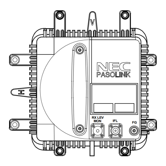
- Page 66 OPERATION ROI-S04605 3.2 Controls, Indicators and Test Jacks The controls, indicators and test jacks of the ODU are shown in Fig. 3-2. These functions are described as follows. RX LEV RX REV MON Fig. 3-2 Controls, Indicators and Test Jacks for 7-38 GHz Band ODU RX LEV MON jack: •...
- Page 67 Provide a DC voltage for RX LEV monitoring and OW signal from / to the ODU. HEADSET jack: Permits communication between IDU and ODU when orderwire headset is connected. METER OW SWITCH PASOLINK OW INDICATOR ANTENNA POINTING MONITOR VOL CONTROL BATTERY (6F22(UB)/9V) RX LEV/OW IN JACK...
- Page 68 Pasolink Digital microwave radio system Installation guide...
- Page 69 PASOLINK installation procedure Preparation work Preparation work is that work done before going to install any site. That work include the following steps: Packing list check During the packing list check, we shall determine which case include which items (materials)
- Page 70 PASOLINK installation procedure Equipment and Materials list This list depending on the following conditions: 1- All sites will use one antenna configuration; 2- The equipment and materials for one site one direction only. Equipment list: 1- Antenna Check the frequency plan and the link calculation for the antenna diameter 2- Hybrid.
- Page 71 PASOLINK installation procedure Before going to site check list Before going to any site, please be sure you completely prepared the following items: 1- The installation tools. 2- The test equipment ,materials ,and tools.( for test work only) 3- Site installation drawings.
- Page 72 PASOLINK installation procedure Hack saw Description Quantity Hammer (450 g) Set file 5 EA/set(smooth) Flat file 250 mm (second –cut) Flat file 250 mm (smooth) Crimping tool 1.25 – 8 sq. 5N18 Hydraulic crimping tool 14-150 sq. Soldering iron 60 W...
- Page 73 PASOLINK installation procedure Installation Flow Chart The standard installation is summarized in this section. Included herein is information on typical installation work flow and installation guide for IDU installation, ODU installation, antenna (ANT) installation, waveguide connection and cable connections. The installation flow diagram is shown below.
- Page 74 PASOLINK installation procedure Packing list for IDU,ODU,and ANT.: ANTENNA DIRECT MOUNTING TYPE TX High/ Low Sub- band A B C D CH____TX ___MHz RATE NAME PLATE MDP-( )MB-( ) SERIAL No.__________ DATE________ , _______ WEIGHT 4kg(WITH OPTION) (G2680) NEC Corporation...
- Page 75 PASOLINK installation procedure IDU Mounting: The installation procedure for the IDU is shown below. (a) Accessories Required • Screwdriver (b) Procedure for Mounting and Dismounting (1) Mounting Mounting method of IDU is shown in Fig. 2-11. (2) Dismounting For dismounting IDU (if necessary), use the following procedure.
- Page 76 PASOLINK installation procedure Mounting of IDU. Mounting of ODU and ANT.: There are two diffwerent cases as follows: 1- The ODU is direct mounted to the antenna. 2- The ODU is mounted with a separate bracket. According to which case you have ,you will follow the assempling procedure included with each antenna And you will know how to fix that ODU.
- Page 77 PASOLINK installation procedure Frame Grounding: In mounting the IDU and odu, perform frame groungding. Location of frame grounding in each of IDU and ODU is shown below: January 2002...
- Page 78 PASOLINK installation procedure Cable Termination: In the following, list of tools and material and the method for cable termination are described. The following cables are described for reference. • BNC connector • D-sub connector • N-P connector • Molex M5557-4R connector Note: Use ISO standardized screw (mm unit) for D-SUB connector.
- Page 79 PASOLINK installation procedure Terminating Coaxial (Baseband Signal) Cable with BNC Connector: January 2002...
- Page 80 PASOLINK installation procedure Terminating Coaxial (IF Signal) Cables with N-P Connector: January 2002...
- Page 81 PASOLINK installation procedure January 2002...
- Page 82 PASOLINK installation procedure Terminating Power Supply Cables with Molex Connector: January 2002...
- Page 83 PASOLINK installation procedure Hand Crimping Outside diameter Tool type of cable position 57026-5000 Φ1.5 to 1.8 Φ1.8 to 2.2 57027-5000 Φ2.3 to 2.6 Φ2.6 to 3.1 WIRE STRIP LENGTH January 2002...
- Page 84 PASOLINK installation procedure Cable and Terminal Connections: During cables and terminal connections, refer to the following connecting method. Caution: Please pay attention not to load excessive force at BNC connector on IDU. In case of tying up cables with BNC connectors in a bundle, please fix them on bay (or something support) within one meter length from IDU.
- Page 85 PASOLINK installation procedure TERMINAL DESCRIPTION Waterproof Protection: LA PORT (D-sub Connector,15 Pins) Control/Monitoring signal input/output from/to personal computer Pin 1 After cable connection, the following part shall be wrapped by Pin 3 Pin 4 self-bonding Pin 5 Pin 11 LOCAL CTS tape for waterproof (see Following Fig.
- Page 86 OPR SEL No.1-No.2 switch on the IDU to the working channel side, then, turn on the power switch of the not working channel. Allow equipment to warm up for at least 30 minutes. Power Switch PASOLINK LINE IN Connector CALL RESET MAINT...
- Page 87 OPERATION ROI-S04488 3.3.2 Shut-down Step Procedure Turn off the POWER switch on the front of the IDU. Note: In 1+1 system, before turn off the POWER switch of No.1 or No. 2 channel, check that the OPR SEL No.1 - No.2 switch is set to channel position to be working.
- Page 88 OPERATION ROI-S04488 The pin assignment is shown in Fig. 3-6. The cable length of RS-232C between the personal computer and IDU equipment shall be less than 15 IDU SIDE PERSONAL COMPUTER SIDE LA PORT/NMS/RA CONNECTOR SIGNAL SIGNAL NAME NAME (BLACK) D-SUB CONNECTOR (9 PIN) D-SUB CONNECTOR (15 PIN) Interface Terminal (9 pin - 15 pin)
- Page 89 OPERATION ROI-S04488 PASOLINK CALL RESET RS-232C MAINT CABLE(BLACK) FUSE (7.5A) − SELV NMS/RA LA PORT PASOLINK RESET MAINT FUSE (7.5A) − SELV LA PORT PERSONAL COMPUTER PASOLINK CALL RESET No.1 − NMS/RA LA PORT No.2 PASOLINK RESET MAINT FUSE (7.5A) −...
- Page 90 OPERATION ROI-S04488 Step Procedure Enter the specified password from the keyboard and press the “Enter” key, Password Note: When the PC is connected to the NMS/RA terminal to control the opposite station, enter password for that station. Press the “0” key and “Enter” key. Then, perform step 8. If the password should be changed, press the “1”...
- Page 91 OPERATION ROI-S04488 Step Procedure Press the “1” key and “Enter” key, then, following setting menu is displayed, Setting Bit rate (4×2MB) AIS RCVD alarm/status (status) AIS SEND alarm/status (status) TX/RX frequency (5ch) TX power ctrl(0dB) Main channel usage 1-16 (used: UNNN NNNN #### ####) BER alarm threshold (10-4) Frame ID (0) WS channel usage (not used)
- Page 92 OPERATION ROI-S04488 Step Procedure “N” : signifies not used channel in alarmed or controlled status for each E1 channel . “U” : signifies E1 channel which is used. 6. In item No. 10 and item No. 11, 232 (i.e. RS232C) is standard.
- Page 93 OPERATION ROI-S04488 Step Procedure Notes: Set to “on” for the following channels. 1. Restricted E1 channels by hardware, which are indicated by “#”on the Setting display. 2. E1 channels which are not available to use when 10/ 100BASE-T(X) LAN is assigned. (see Table 3-3 Applicable Traffic Channel) 3.
- Page 94 OPERATION ROI-S04488 Step Procedure Press the “8” key and “Enter” key, then, following item is displayed, Frame ID (0) Input ID No. (0-7) : Press the desired frame ID number and “Enter” key for setting, if not, press the “Esc” key, Note: The frame ID number must be set to the same number as that on the MAIN BOARD at the opposite station as follows (factory setting status):...
- Page 95 OPERATION ROI-S04488 Step Procedure Enter 11 and the “Enter” key, then, following item is displayed, 11. DSC 2 (232) DSC 2 (232:0 / 422:1 / 485(TERM):2 / 485(NON TERM):3): Press any “0” to “3” key and “Enter” key for setting, if not, press the “Esc”...
- Page 96 OPERATION ROI-S04488 Step Procedure For 1+0 System 13. Alarm table 1/2 Form C1 Form C2 Form C3 Form C4 INPUT LOSS AIS RCVD AIS SEND OUTPUT LOSS ...
- Page 97 OPERATION ROI-S04488 Step Procedure 3. The items which are applied alarm output are indicated with “OUT” and not applied alarm output are indicated with “–”. 4. Selecting item No. changes depending on the mounted modules. 5. The outputs which are shut off the signal output in maintenance conditions are indicated with "MASK".
- Page 98 OPERATION ROI-S04488 Step Procedure 12. Alarm table 3/3 28. TX PWR ALM 1 29. TX PWR ALM 2 30. RX LEV ALM 1 ...
- Page 99 OPERATION ROI-S04488 Step Procedure When press the “1” key and “Enter” key in previous step 32, following Form setting for Item No.1 is displayed, For 1+0 System Select item No. (1-23,0:no change):1 Form C1 Form C2 Form C3 Form C4 ...
- Page 100 OPERATION ROI-S04488 Step Procedure Press the “1” key and “Enter” key for setting, or press the “0” key and “Enter” key for cancel, When pressed the “0” key and “Enter” key in previous step 36, following setting for other Form is displayed, For 1+0 System Form C1 (output-no:0/yes:1) :0 Form C1...
- Page 101 OPERATION ROI-S04488 3.4.2 Alarm and Status Monitoring of IDU and ODU Alarm conditions are identified by the IDU indicator on the IDU. Also the working conditions of the IDU and ODU can be monitored by the PC, as follows: Step Procedure Connect the personal computer (PC) to the LA PORT of the IDU using an RS-232C cable as shown in Fig.
- Page 102 OPERATION ROI-S04488 Step Procedure For 1+1 System Monitoring Monitoring voltage Alarm/Status Inventory 00. Menu 99. Exit Select item No. : Alarm and Status Press the “3” for 1+0 (or “2” for 1+1) key and “Enter” key, then, following alarm items are displayed, For 1+0 System Monitoring of alarm/status 1/2 INPUT LOSS 1-16...
- Page 103 OPERATION ROI-S04488 Step Procedure Monitoring of alarm/status 2/2 MOD ALM (alarm:-) DEM ALM (alarm:*) OPR ALM (alarm:*) TX PWR ALM (alarm:-) RX LEV ALM (alarm:-) APC1 ALM (alarm:-) APC2 ALM (alarm:-) IF INPUT ALM (alarm:-) MUTE (off) TX/RX FREQ CH (5ch) Press any key to continue …...
- Page 104 OPERATION ROI-S04488 Step Procedure Notes: 1. “∗” : indicates alarm condition. 2. “−” : indicates normal condition. 3. Monitoring of alarm/status displayed on the LCT depend on system configuration. 4. CHANNEL USAGE ERROR 1-16 is displayed only when “Channel usage error (report)” is selected to “report”...
- Page 105 OPERATION ROI-S04488 Step Procedure For 1+0 System Monitoring Monitoring voltage Monitoring voltage (continuance mode) Alarm/Status Inventory 00. Menu 99. Exit Select item No. : For 1+1 System Monitoring Monitoring voltage Alarm/Status Inventory 00. Menu 99. Exit Select item No. : Press “4”...
- Page 106 OPERATION ROI-S04488 Step Procedure Inventory 2/2 Manufactured data JAN/2003 Software version (ROM) Bit rate 17/34MB RF band 23GHz Low Sub band Shift freq 1200 MHz CH separation 2.50 MHz For 1+1 System 3.Inventory 1/4 SW UNIT Serial number 123456 Manufactured date OCT/2002 Software version (ROM/RAM) 1.20/2.14 Bit rate...
- Page 107 Shift freq 1200MHz CH separation 2.50MHz Press any key Press the “Esc” key to go back to the Monitoring menu, then, enter 99 to exit the monitoring of the Pasolink. Monitoring Monitoring voltage Monitoring voltage (continuance mode) Alarm/Status Inventory 00. Menu 99.
- Page 108 OPERATION ROI-S04488 3.4.3 Monitoring the ODU The following items of the ODU can be monitored on the PC. • Transmitter output power • Received signal level The procedure is as follows: Step Procedure Connect the personal computer (PC) to the LA PORT of the IDU using an RS-232C cable as shown in Fig.
- Page 109 OPERATION ROI-S04488 Step Procedure Press the “3” key and “Enter” key, then, following menu is displayed, For 1+0 System Monitoring Monitoring voltage Monitoring voltage (Continuance mode) Alarm/Status Inventory 00. Menu 99. Exit Select item No. : For 1+1 System Monitoring Monitoring voltage Alarm/Status Inventory...
- Page 110 OPERATION ROI-S04488 Step Procedure Press the “Esc” key to go back to the Monitoring menu, then, enter 99 to exit the monitoring of the Pasolink. For 1+0 System Monitoring Monitoring voltage Monitoring voltage (Continuance mode) Alarm/Status Inventory 00. Menu 99. Exit Select item No.
Need help?
Do you have a question about the PASOLINK and is the answer not in the manual?
Questions and answers