Danfoss MCO 305 Operating Instructions Manual
Hide thumbs
Also See for MCO 305:
- Operating instructions manual (45 pages) ,
- Design manual (265 pages) ,
- Design manual (242 pages)
Table of Contents
Advertisement
Quick Links
MCO 305 Operating Instructions
Contents
How to Read these Operating Instructions ..............................3
Safety Instructions and General Warnings ...............................7
How to Install ..........................................................................9
Optimizing the PID controller................................................. 27
How to Install the Application ................................................ 35
How to Read these Operating Instructions .......................................................3
Approvals ...................................................................................................5
Symbols and Conventions .............................................................................5
Abbreviations ..............................................................................................5
Abbreviations ..............................................................................................6
High Voltage Warning ...................................................................................7
Safety Instructions .......................................................................................7
Before Commencing Repair Work ...................................................................8
Avoid Unintended Start .................................................................................8
Safe Stop of FC 302 .....................................................................................8
General Warning ..........................................................................................8
How to Get Started.......................................................................................9
System Overview ....................................................................................... 10
Commissioning Guide ................................................................................. 18
Basic MCO Parameter Settings ..................................................................... 18
Connecting and Testing the Encoder(s) ......................................................... 21
PID Controller Settings ............................................................................... 22
Executing a Test Program............................................................................ 25
How the Control Process Works .................................................................... 27
Significance and Influence of the Controller Parameters ................................... 27
PID Factors ............................................................................................... 29
Optimizing your Controller Settings Step-by-Step ........................................... 31
Download Application Program and Configuration ........................................... 35
Backup and Restore ................................................................................... 35
How to Connect and Run Multiple Drives........................................................ 36
MG.33.K2.02 - VLT is a registered Danfoss trademark
1
Advertisement
Table of Contents

Related Manuals for Danfoss MCO 305


Summary of Contents for Danfoss MCO 305
-
Page 1: Table Of Contents
MCO 305 Operating Instructions Contents How to Read these Operating Instructions ......3 How to Read these Operating Instructions ............3 Available Literature for FC 300, MCO 305 and MCT 10 Motion Control Tool ...4 Approvals ....................5 Symbols and Conventions ................5 Abbreviations ....................5 Abbreviations ....................6... - Page 2 Danfoss A/S, 2007 Trademarks VLT is a registered Danfoss trademark. Microsoft, MS, MS-DOS, Windows 2000, and Windows XP are either registered trademarks or trademarks of the Microsoft Corporation in the USA and other countries. MG.33.K2.02 – VLT is a registered Danfoss trademark...
-
Page 3: How To Read These Operating Instructions
These Operating Instructions will help you get started, install, program, and troubleshoot your Motion Control Option MCO 305. Please read these operating instructions in full and, in order to be able to work with the system safely and professionally, particularly observe the hints and cautionary remarks. -
Page 4: Available Literature For Fc 300, Mco 305 And Mct 10 Motion Control Tool
Parameter Reference in the MCO 305 DesignGuide for more details. Available Literature for FC 300, MCO 305 and MCT 10 Motion Control Tool The MCO 305 Design Guide entails all technical information about the option board and customer design and applications. -
Page 5: Approvals
Values for use to select the parameter options are written in brackets, e.g. [3]. Keys The names of keys and function keys are printed in brackets, for example the control key [Cntl] key, or just [Cntl], the [Esc] key or the [F1] key. MG.33.K2.02 – VLT is a registered Danfoss trademark... -
Page 6: Abbreviations
Motion Control Option Motion Control Tool Parameter par. Protective Extra Low Voltage PELV Position Control Loop Pulses per Revolution Quad-counts Revolutions per Minute Second Switch normally closed Switch normally open User Unit Volts MG.33.K2.02 – VLT is a registered Danfoss trademark... -
Page 7: Safety Instructions And General Warnings
MCO 305 Operating Instructions Software version: 4.xx These Operating Instructions can be used for the MCO 305 option board with all FC 300 frequency converters with software version 4.0x. The software version number can be seen from parameter 15-43. High Voltage Warning The voltage of the FC 300 is dangerous whenever the converter is connected to mains. -
Page 8: Before Commencing Repair Work
= The waiting time using the VLT AutomationDrive FC 300 is different for different sizes: Please see period of waiting time xx in the FC 300 Operating Instructions. MG.33.K2.02 – VLT is a registered Danfoss trademark... -
Page 9: How To Install
MCO 305. The installation procedure depends on whether the MCO 305 was delivered as an option for upgrading an existing FC 300 or if it was preinstalled before delivery. Skip the next chapter (Mechanical installation) if the... -
Page 10: System Overview
And all MCO 305 programs and arrays are deleted! System Overview Mechanical Installation (Only relevant if the MCO 305 is delivered as option for upgrading an existing FC300) Frame size A2 and A3 MG.33.K2.02 – VLT is a registered Danfoss trademark... - Page 11 MCO 305 Operating Instructions __ How to Install __ Frame size A5, B1 and B2 Accessory Bag Accessory bag A2 and A3 enclosures: MG.33.K2.02 – VLT is a registered Danfoss trademark...
- Page 12 MCO 305 Operating Instructions __ How to Install __ Installation kit A5 enclosure: Installation kit B and C enclosure: MG.33.K2.02 – VLT is a registered Danfoss trademark...
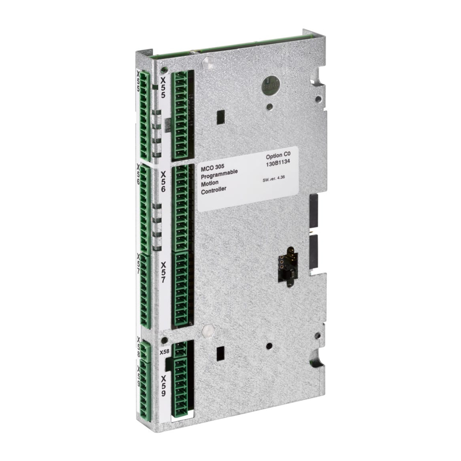
- Page 13 EMC correct cable installation. MCO 305 Control Terminals Frame size A2 and A3: All MCO 305 terminals are located behind the C- option terminal cover, see illustration. Frame size A5, B1 and B2: All MCO 305 terminals are located next to the FC 300 control card.
- Page 14 MCO 305 control terminals are plug connectors with screw terminals; the terminal blocks are duplicated to enable use of the same MCO 305 in all frame sizes. See illustration to locate the terminal blocks: (1) is used with frame sizes A2 and A3,...
- Page 15 +5V Supply Digital Output/Input Digital Output/Input Digital Output A not Digital Output Digital Output B not Digital Output Z / Clock Digital Output Z not / Clock not Digital Output DATA DATA not MG.33.K2.02 – VLT is a registered Danfoss trademark...
- Page 16 5 V incremental encoder (RS422) supplied by an MCO 305: external power source: 24 V absolute encoder (SSI) supplied by 24 V absolute encoder (SSI) supplied by an MCO 305: external power source: MG.33.K2.02 – VLT is a registered Danfoss trademark...
- Page 17 MCO 305 Operating Instructions __ How to Install __ Virtual master connection: When more than 2 MCO 305 master encoder interfaces are interconnected termination must be on (par. 32-40 = ON) at both ends of the bus. Termination must be off (par. 32-40 = OFF) in all other MCO's.
-
Page 18: Commissioning Guide
__ How to Install __ Commissioning Guide This guideline is only describing basic configuration and optimizing of MCO 305, before starting the following steps must be completed: 1. Basic commissioning of FC 300. NOTE: FC 300 must be optimized and have good control over the motor and application before commissioning MCO 305! Guidelines can be found in FC 300 Operating Instructions (MG.33.AX.XX). - Page 19 Define par. 32-81 Shortest Ramp. That is the time from 0 to maximum velocity and from maximum velocity to 0. All acceleration and deceleration commands (ACC, DEC) are related to this value. MG.33.K2.02 – VLT is a registered Danfoss trademark...
- Page 20 When using the encoder zero pulse as marker signal the distance between 2 markers is the resolution (qc) of the encoder. When external marker signals are used, the marker distance can be measured by means of the program sample “Marker count” (see chapter program samples) if it is unknown. MG.33.K2.02 – VLT is a registered Danfoss trademark...
-
Page 21: Connecting And Testing The Encoder(S)
For a full rota- tion you should receive 4 times the value of the resolution of the encoder, that means 2000 if the Encoder Counts per Revolution is 500. MG.33.K2.02 – VLT is a registered Danfoss trademark... -
Page 22: Pid Controller Settings
Encoder type (par. 32-00 and 32-02), Encoder resolution (par. 32-01 or 32-03), Encoder velocity (par. 19-00), and Motion type (par. 19-00). These parameters must thus be set before starting the calculation. The program performs the following steps when setting input 1: MG.33.K2.02 – VLT is a registered Danfoss trademark... - Page 23 = 0 // Reset flag save_done = 0 // Reset flag OUT 1 0 // Reset output OUT 2 0 // Reset output ENDIF GOTO MAIN /********************** Sub programs start **************************************/ SUBMAINPROG MG.33.K2.02 – VLT is a registered Danfoss trademark...
- Page 24 // Reset error when Input 8 is high. ERRCLR // Clear error err=0 // Reset error flag ENDIF ENDWHILE OUT 8 0 // Reset error output RETURN /******************************************************************************/ ENDPROG /*************************** End of program **************************************/ MG.33.K2.02 – VLT is a registered Danfoss trademark...
-
Page 25: Executing A Test Program
Click on Development and start the test program with Execute or [F5]. The test is successful if the motor runs slowly back and forth and position 500 is registered. End the test with [Esc] and Close the File. MG.33.K2.02 – VLT is a registered Danfoss trademark... - Page 26 Check the connections of the motor or encoder. If the connections are correct, then it is necessary to increase the par. 32-67 Maximum Tolerated Position Error. (See Optimizing the PID controller.) MG.33.K2.02 – VLT is a registered Danfoss trademark...
-
Page 27: Optimizing The Pid Controller
The PID control unit of the APOSS motion controller transfers the necessary output frequency via an internal speed reference to the FC 300. This set value is periodically recalculated with an interval of one millisecond (interval is programmable by the TIMER parameter). The MCO 305 is by default set with soft 'fit for all' controller parameters. - Page 28 In SYNCV mode the PID controller is working with speed deviation instead of position deviation. Speed deviation is calculated by CV–AV. The controller in the MCO 305 utilizes two control strategies at the same time: 1. An open-loop feed-forward control. Since the asynchronous motor inherently has a good open loop performance the feed-forward control is a very important part of the controller in most applications.
-
Page 29: Pid Factors
FC 300. Cutting of power to the motor (by setting terminal 27 low) while little positioning deviance is present in the controller, could result in an enormous control signal being generated once the power is turned back on. MG.33.K2.02 – VLT is a registered Danfoss trademark... - Page 30 30% of the calculated set value. However, then it is necessary also to use the feed-forward part of the controller in order to achieve the corresponding control. MG.33.K2.02 – VLT is a registered Danfoss trademark...
-
Page 31: Optimizing Your Controller Settings Step-By-Step
View the velocity profiles: If the Actual Velocity profile is lower than the Commanded Velocity profile, increase Velocity Feed-forward and Start the test run again. Of course if the Actual Velocity profile is higher than the specified Commanded Velocity you should decrease Velocity Feed-forward. MG.33.K2.02 – VLT is a registered Danfoss trademark... - Page 32 If you are using the Integral part of the PID controller, remember to reduce the par. 32-63 Limit Value for Integral Sum as much as possible (without losing the Integral Factor effect of course) in order to reduce oscillations and overshoot as much as possible. MG.33.K2.02 – VLT is a registered Danfoss trademark...
- Page 33 The theoretical maximum acceleration will also not be achieved if, for example, the PID controller output is too small or the FC 300/motor is not sized correctly and therefore does not provide enough energy for peak consumption during acceleration. MG.33.K2.02 – VLT is a registered Danfoss trademark...
-
Page 35: How To Install The Application
6. Open the folder “Project – Drive – MCO 305 – Arrays”. 7. Right click on the file and select “Import” or “Edit”. 8. Right click on the MCO 305 folder in the tree structure in the left-hand view of MCT 10 and select “Write to drive”. -
Page 36: How To Connect And Run Multiple Drives
Now both parameters and MCO 305 data is restored in the drive. Backup and Restore via LCP Both parameters and MCO 305 data can be stored in the LCP and thus restored from the LCP to another drive. Use the following steps to back-up parameters data in the LCP: 1. -
Page 37: General Specifications
Encoder signals are monitored during operation and standstill. Customer specific application programs can be copy protected. All MCO 305 parameters including user defined application parameters are accessible via the FC 300 Local Control Panel. MCO 305 can be combined with other FC 300 options e.g. PROFIBUS and DeviceNet interface. - Page 38 Cable type ......Screened cable with a twisted pair of wires for each encoder channel Incremental encoder specifications Incremental encoder type ..................RS422/TTL Maximum frequency ....................410 kHz Phase displacement between A and B................90˚± 30˚ Maximum cable length ....................300m MG.33.K2.02 – VLT is a registered Danfoss trademark...
- Page 39 Application program Program memory size ................... 100 Kbytes Maximum number of application programs ................90 Average command execution time ................0.3 ms Maximum reaction time on interrupt input ................ 1 ms MG.33.K2.02 – VLT is a registered Danfoss trademark...
-
Page 40: Supply Voltage Overview
MCO 305 Operating Instructions __ General Specifications __ Supply Voltage Overview MG.33.K2.02 – VLT is a registered Danfoss trademark... -
Page 41: Troubleshooting
Programs in memory are corrupted. Reset by CPU Reset by CPU. User abort User abort. HW end limit HW end limit activated. Too many inter. Too many interrupt functions. No ext. 24V External supply is missing. MG.33.K2.02 – VLT is a registered Danfoss trademark... - Page 42 Error 107 Home vel. Zero An attempt was made to execute the HOME command but the motor is set to 0 in par. 33-03 Velocity of Home Motion. MG.33.K2.02 – VLT is a registered Danfoss trademark...
- Page 43 (ex factory) and to delete all (SET or SETVLT command), which does not exist. user programs, arrays, and application parameters. Afterwards re-load the programs and parameters. This corresponds to a Reset complete in the APOSS menu. MG.33.K2.02 – VLT is a registered Danfoss trademark...
- Page 44 Remember to follow the recommendations The error usually occurs when there is a recurrent concerning saving programs and reference to one of the sub-programs in a sub- parameters before deleting the EEPROM. program. MG.33.K2.02 – VLT is a registered Danfoss trademark...
- Page 45 If such an error should occur, please contact your dealer and report the error number displayed to NB!: the technical service department. Remember to follow the recommendations concerning saving programs and parameters before deleting the EEPROM. MG.33.K2.02 – VLT is a registered Danfoss trademark...
-
Page 46: Aposs Software Messages
If the FC 300 is turned off or the plug is pulled, etc. the window is disconnected from the FC 300 and the lost connection is registered. Timeout: no reply from FC The FC 300 does not answer; check the connection. MG.33.K2.02 – VLT is a registered Danfoss trademark... -
Page 47: Appendix
Please see for all data types the FC 300 Design Data type Description Type Guide. Integer 8 Int8 Integer 16 Int16 Integer 32 Int32 Unsigned 8 Uint8 Unsigned 16 Uint16 Unsigned 32 Uint32 MG.33.K2.02 – VLT is a registered Danfoss trademark... - Page 48 [1] No action TRUE 1-set-up Uint8 32-11 POSFACT_N User Unit Denominator TRUE 1-set-up Uint32 32-12 POSFACT_Z User Unit Numerator TRUE 1-set-up Uint32 default setting value for use in communication via serial communication port MG.33.K2.02 – VLT is a registered Danfoss trademark...
- Page 49 32-81 RAMPMIN Shortest Ramp TRUE 1-set-up Uint32 32-82 RAMPTYPE Ramp Type TRUE 1-set-up Uint8 32-83 VELRES Velocity Resolution TRUE 1-set-up Uint16 default setting value for use in communication via serial communication port MG.33.K2.02 – VLT is a registered Danfoss trademark...
- Page 50 Marker Number for Ready TRUE 1-set-up Uint16 33-26 SYNCVFTIME Velocity Filter TRUE 1-set-up Int32 33-27 SYNCOFFTIME Offset Filter Time 0 ms TRUE 1-set-up Uint32 default setting value for use in communication via serial communication port MG.33.K2.02 – VLT is a registered Danfoss trademark...
- Page 51 Terminal X59/1 and X59/2 [0] Output FALSE 1-set-up Uint8 Mode 33-61 I_FUNCTION_11 Terminal X57/11 Digital [0] no function TRUE 1-set-up Uint8 Input default setting value for use in communication via serial communication port MG.33.K2.02 – VLT is a registered Danfoss trademark...
- Page 52 PCD 7 Write to MCO 1-set-up Uint16 34-08 PCD 8 Write to MCO 1-set-up Uint16 34-09 PCD 9 Write to MCO 1-set-up Uint16 default setting value for use in communication via serial communication port MG.33.K2.02 – VLT is a registered Danfoss trademark...
- Page 53 1-set-up Int32 34-7* Diagnosis Readouts 34-70 MCO Alarm Word 1 FALSE 1-set-up Uint32 34-71 MCO Alarm Word 2 FALSE 1-set-up Uint32 default setting value for use in communication via serial communication port MG.33.K2.02 – VLT is a registered Danfoss trademark...
-
Page 54: Index
Download Application Program and Configuration ..35 KDER ..............29 KILIM..............29 Encoder KINT ..............29 KPROP..............29 absolute encoder specifications ......39 Checking Master Encoder for Synchronizing Applications............ 22 Connecting and Testing........21 Ending the Encoder Check ........22 MG.33.K2.02 – VLT is a registered Danfoss trademark... - Page 55 Position Error is exceeded? ......33 Safe Stop of FC 302..........8 if there is a tendency towards instability? ....33 Safety Instructions ..........7 Sampling Time for PID Control ........ 30 MG.33.K2.02 – VLT is a registered Danfoss trademark...
Need help?
Do you have a question about the MCO 305 and is the answer not in the manual?
Questions and answers