Table of Contents
Advertisement
Advertisement
Table of Contents

Related Manuals for Danfoss MCD 600


Summary of Contents for Danfoss MCD 600
- Page 1 Installation Guide PROFIBUS Card VLT® Soft Starter MCD 600...
-
Page 3: Table Of Contents
5 PROFIBUS Diagnostic Telegram and Flag Diagnostic Telegram Structure 5.1.1 PROFIBUS Trip Code 5.1.2 Changed Parameter Number 6 Supported Modes PROFIBUS Freeze Mode PROFIBUS Sync Mode PROFIBUS Clear Mode 7 Specifications Connections Settings Certification Danfoss A/S © 2018.09 AQ277154583779en-000101 / 175R1181 | 3... -
Page 4: Safety
The installer is responsible for following all instructions in this manual and for following correct electrical practice. Use all internationally recognized standard practice for RS485 communication when installing and using this equipment. 4 | Danfoss A/S © 2018.09 AQ277154583779en-000101 / 175R1181... -
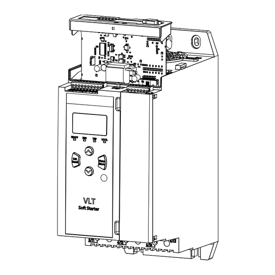
Page 5: Installation
The expansion card must be installed in the soft starter. Procedure 1. Restore control power. 2. Connect field wiring via the DB9 plug. Example: Table 1: DB9 Connector Pin number Assignment Shield 24 V DC negative (optional) Danfoss A/S © 2018.09 AQ277154583779en-000101 / 175R1181 | 5... -
Page 6: Feedback Leds
N O T I C E If communication fails between the device and the network, the Bus Status LED goes off. When communication is restored, the Bus Status LED turns back on. 6 | Danfoss A/S © 2018.09 AQ277154583779en-000101 / 175R1181... -
Page 7: Configuration
3 Configuration 3.1 Preparations Import the latest .gsd file in the Master configuration tool. This file is available from the supplier at www.danfoss.com/en/service-and- support/downloads/dds/fieldbus-configuration-files/#tab-downloads. If the Master uses on-screen icons, 2 graphic bitmap files are available from the website. SSPM_N.bmp indicates normal mode. -
Page 8: Data Structures
5–7 Reserved 0=Stop 1=Start 1–2 Reserved 1=Reset 4–7 Reserved N O T I C E Bit 4 of byte 0 must be set to 0 for the soft starter to start. 8 | Danfoss A/S © 2018.09 AQ277154583779en-000101 / 175R1181... -
Page 9: Soft Starter Monitoring I/O Data Structure
Data value (high byte) Byte 5 Data value (low byte) N O T I C E An invalid data request number results in the invalid data request number bit being set to 1. Danfoss A/S © 2018.09 AQ277154583779en-000101 / 175R1181 | 9... - Page 10 8–15 Average rms current across all 3 phases (high byte) Motor temperature 0–7 Motor thermal model (%) 8–15 Reserved % Power factor 0–7 100% = power factor of 1 8–15 Reserved 10 | Danfoss A/S © 2018.09 AQ277154583779en-000101 / 175R1181...
- Page 11 0–13 Phase 1 voltage 14–15 Reserved Voltage 0–13 Phase 2 voltage 14–15 Reserved Voltage 0–13 Phase 3 voltage 14–15 Reserved Version 0–7 Software minor version number 8–15 Software major version number Danfoss A/S © 2018.09 AQ277154583779en-000101 / 175R1181 | 11...
-
Page 12: Soft Starter Programming I/O Data Structure
High byte parameter value to write to soft starter/0 data values for read 0–7 Low byte parameter value to write to soft starter/0 data values for read 4.4.2 Inputs Table 8: Structure of Master/Slave Input Bytes Byte Bits Details 0–7 Echo parameter number 12 | Danfoss A/S © 2018.09 AQ277154583779en-000101 / 175R1181... - Page 13 Data Structures Byte Bits Details 1=Invalid parameter number 1=Invalid parameter value 2–7 Reserved 0–7 High byte parameter value read from soft starter 0–7 Low byte parameter value read from soft starter Danfoss A/S © 2018.09 AQ277154583779en-000101 / 175R1181 | 13...
-
Page 14: Trip Codes
Forced network trip Internal fault Overvoltage Undervoltage Parameter out of range Input B trip L1 phase loss L2 phase loss L3 phase loss L1-T1 shorted L2-T2 shorted L3-T3 shorted Time-overcurrent (bypass overload) 14 | Danfoss A/S © 2018.09 AQ277154583779en-000101 / 175R1181... - Page 15 Firing fail P2 Firing fail P3 VZC fail P1 VZC fail P2 VZC fail P3 Low control volts 84–96 Internal fault x. Contact the local supplier with the fault code (x). Danfoss A/S © 2018.09 AQ277154583779en-000101 / 175R1181 | 15...
-
Page 16: Profibus Diagnostic Telegram And Flag
If a parameter number is changed via the LCP, the affected parameter number is reported in byte 2. When the Master reads or writes the changed parameter, byte 2 is reset = 0. A changed parameter number does not set a diagnostic flag. 16 | Danfoss A/S © 2018.09 AQ277154583779en-000101 / 175R1181... -
Page 17: Supported Modes
In Sync Mode, commands to the soft starter are not processed until another sync action is carried out. An unsync action returns the device to normal operation. 6.3 PROFIBUS Clear Mode If the Master sends a global clear command, the device sends a quick stop command to the soft starter. Danfoss A/S © 2018.09 AQ277154583779en-000101 / 175R1181 | 17... -
Page 18: Specifications
2.5 mm (14 AWG) 7.2 Settings Address range 1–125 Data rate (bps) 9.6 kb/s–12.0 Mb/s (auto-detect) 7.3 Certification IEC 60947-4-2 EN 60947-4-2 RoHS Compliant with EU Directive 2011/65/EU Illustration 2: PROFIBUS International 18 | Danfoss A/S © 2018.09 AQ277154583779en-000101 / 175R1181... - Page 19 Index Index Basic mode Control word structure Data structure Output Input DB9 plug Diagnostic flag 16, 16 Expansion card Expansion port cover Extended mode Parameter upload/download mode Telegram Tools Flat-bladed screwdriver Danfoss A/S © 2018.09 AQ277154583779en-000101 / 175R1181 | 19...
- Page 20 Installation Guide | PROFIBUS Card 20 | Danfoss A/S © 2018.09 AQ277154583779en-000101 / 175R1181...
- Page 21 Installation Guide | PROFIBUS Card Danfoss A/S © 2018.09 AQ277154583779en-000101 / 175R1181 | 21...
- Page 22 Danfoss can accept no responsibility for possible errors in catalogues, brochures and other printed material. Danfoss reserves the right to alter its products without notice. This also applies to products already on order provided that such alterations can be made without subsequential changes being necessary in specifications already agreed. All trademarks in this material are property of the respective companies.
Need help?
Do you have a question about the MCD 600 and is the answer not in the manual?
Questions and answers