Table of Contents
Advertisement
Quick Links
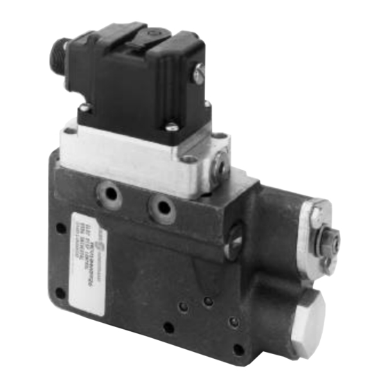
DESCRIPTION
The MCV109A Electrical Displacement Control (EDC-MV) is
a two-stage electrohydraulic motor stroke control which uses
mechanical feedback to establish closed loop control of the
swashplate angle of Danfoss Series 2X and Series
3X motors.
The first stage, the MCV116 Pressure Control Pilot, is a
torque motor actuated, double nozzle flapper valve that
produces a differential output pressure proportional to the
applied electrical signal. The second stage uses the differen-
tial pressure to drive its double spool arrangement and port
oil to the motor servo cylinders.
FEATURES
•
Single command source can be used to control both
hydrostatic pump and motor
•
Servo control deadband independent of signal null
deadband: offers safety combined with accurate and
responsive control.
•
Resistance to the environment: standard silicone oil filled
torque motor, environmentally sealed first/second stage
interface, full environmental testing.
ORDERING INFORMATION
MCV109s are ordered for the particular motor on which they
are to be mounted. Link Installation Kits, as ordered in the
table below, include: orifices, retaining ring, drag link, spacer
plate, swashplate pin, link and ball assembly, hex screws, O-
rings and gaskets. In some cases not all the above are
necessary for installation and they are not included in the kit.
TABLE A. INFORMATION NECESSARY TO SPECIFY
THE LINK INSTALLATION KIT.
MOTOR SERIES
Order the valve itself through the following table:
TABLE B. INFORMATION NECESSARY TO SPECIFY
THE ELECTRICAL DISPLACMENT CONTROL.
PILOT STYLE
© Danfoss, 2013-09
MCV109A
Electrical Displacement Control
BLN-95-8985-1
•
•
•
•
The EDC Pilot comes in five styles:
PILOT STYLE
KK041
XX
The standard EDC Pilot is a single coil (one input to the
torque motor) (see Block Diagram), silicone oil filled, Packard
Connector device. The options are a dual coil, which allows
two command sources to be combined at the torque motor,
the resulting signal being the difference between the two, a
MS3102C14S-2P (Danfoss Part Number K01314)
connector.
MCV109A59
XX
BLN-95-8985-1
Pilot supply screens in series, upstream screen is exter-
nally serviceable
First and second stages can be individually replaced
Swashplate movement can be visually detected
Single or dual coil torque motor
DESCRIPTION
22
Single Coil, Packard Connector
23
Dual Coil, Packard Connector
26
Single Coil, MS Connector
27
Dual Coil, MS Connector
.
.
MV
-
Issued: June 1995
1
Advertisement
Table of Contents

Related Manuals for Danfoss MCV109A


Summary of Contents for Danfoss MCV109A
- Page 1 Electrical Displacement Control Issued: June 1995 BLN-95-8985-1 DESCRIPTION The MCV109A Electrical Displacement Control (EDC-MV) is a two-stage electrohydraulic motor stroke control which uses mechanical feedback to establish closed loop control of the swashplate angle of Danfoss Series 2X and Series 3X motors.
-
Page 2: Spare Parts
Order the EDC either factory installed on motors or as an See the Spare Parts diagram for a list of spare parts available individual control. for the MCV109A. Other non-standard spare parts, such as orifices, may be available upon request. Order Danfoss Pressure Override Valve through... -
Page 3: Technical Data
TECHNICAL DATA ELECTRICAL HYDRAULIC THRESHOLD/RATED OUTPUT CURRENT FLUID The current required to come off stroke (threshold) and Automatic transmission fluid or hydraulic oil, such as to reach full 6° destroke (rated output) will be per the Mobil DTE 24 or equivalent following table. -
Page 4: Performance Curve
WIRING DIAGRAM (Typical) MCH CONTROL HANDLE MCV104 MCV109 GROUND 1444 PERFORMANCE CURVE WIRING SCHEMES Single coil 140 mA with 3.3 Vdc input at full destroke. Using one of the two dual coils, 185 mA with 2.8 Vdc (C, D) or 3.6 Vdc (A, B) input at full destroke. -
Page 5: Theory Of Operation
MCV109A. The input current commands the the pilot system is in equilibrium. It is this pressure feedback pilot's torque motor stage, a bridge network consisting of an... - Page 6 INTERNAL WORKINGS SCHEMATIC 1303 Schematic of the Internal Workings of the MCV109A. Oil Paths Shown Externally for Clarity. ENVIRONMENTAL TEMPERATURE 1. Cycling from 5 to 2000 Hz in each of the three axes. The valve shall be functional and undamaged at oil 2.
- Page 7 WIRING (continued) The distance from the back of the tangs to the furthest To assemble the female tower connector, use the follow- rib may not exceed 19.5 millimeters. See Distance, ing directions: Packard Connector diagram. Isolate the wires that extend from the command source to the EDC.
-
Page 8: Installation
INSTALLATION A highly reliable connection between the swashplate and the TABLE C. THE FOLLOWING TABLE CORRELATES THE drag link is necessary for safe operation. An unreliable MOTOR SERIES NUMBER WITH THE SERIES NUMBER connection may result in loss of feedback with a resulting loss STAMPED ON THE SIDE OF THE CONTROL FEEDBACK of control. -
Page 9: Pin Connection
PIN CONNECTION SWASHPLATE ASSEMBLY DRAG LINK REMOVE "E" RINGS, PIN AMD DRAG LINK 1125C 1126B Location of Swashplate Assembly in Motor Housing. Pin Connection to Swashplate. Shown Disassembled for Clarity. MOUNTING (continued) C. Lubricate the shaft O-ring and replace the bushing MOUNTING THE NEW HARDWARE over the shaft. - Page 10 MCV109A threshold adjustments. There should be no "dead spots" in Reconnect the wires to the EDC-MV. Re-start the hydro- which increased command gives no increased speed.
-
Page 11: Customer Service
CUSTOMER SERVICE NORTH AMERICA EUROPE ORDER FROM ORDER FROM Danfoss (US) Company Danfoss (Neumünster) GmbH & Co. Customer Service Department Customer Service Department 3500 Annapolis Lane North Krokamp 35 Minneapolis, Minnesota 55447 Postfach 2460 Telephone: (763) 509-2084 D-24531 Neumünster Fax: (763) 559-0108...
Need help?
Do you have a question about the MCV109A and is the answer not in the manual?
Questions and answers