
Subscribe to Our Youtube Channel
Related Manuals for GE VAT300 Series


Summary of Contents for GE VAT300 Series
- Page 1 GE Consumer & Industrial Power Protection VAT300 Quick guide Guía rápida Kurzanleitung Guide rapide Guida Rapida GE imagination at work...
- Page 2 GE Consumer & Industrial Power Protection VAT300 Quick guide EN 1 to 33 Guía rápida ES 1 to 33 Kurzanleitung DE 1 to 34 Guide rapide FR 1 to 33 Guida rapida IT 1 to 33...
- Page 3 This information is provided on the CD-ROM included in the container this device was packaged in. It should be retained with this device at all times. A hard copy of this information may be ordered to GE Dealer GE Consumer & Industrial PCST-3449A Jan.2008...
- Page 4 <Preface> WARNING ALWAYS READ THIS MANUAL THOROUGHLY BEFORE USING THE VAT300. THIS INVERTER CONTAINS HIGH VOLTAGE CIRCUITS THAT MAY BE FATAL TO HUMANS. USE EXTREME CAUTION DURING INSTALLATION. MAINTENANCE MUST BE PERFORMED BY QUALIFIED TECHNICIANS, AND ALL POWER SOURCES MUST BE DISCONNECTED BEFORE ANY MAINTENANCE.
- Page 5 1. Transportation and installation CAUTION • Always transport the product with an appropriate amount according to the products weight. • Install the inverter, dynamic braking unit and resistor, and other peripheral devices on non-combustible material such as metal. • Do not place the product near inflammable items. •...
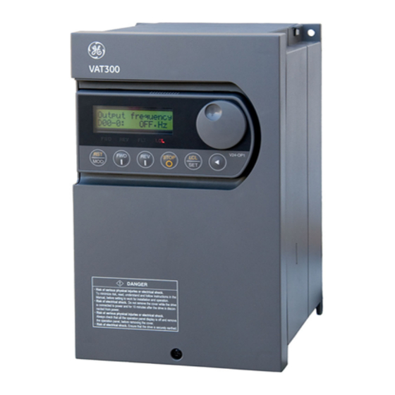
- Page 6 Chapter1 Names of each part Operation panel Front cover Cooling fan installation case Main body case Fig.1-1 For N018K5, H030K0 and smaller Operation panel Main body case Front cover Fig.1-2 For N022K0, X037K0 and larger The presence and quantity of cooling fans will differ according to the capacity. Remove the inverter from the packaging, and check the details on the rating nameplate to confirm that the inverter is as ordered.
- Page 7 Chapter 2 Installation and Wiring 2-1 Installation environment Observe the following points when installing the inverter. (1) Install the inverter vertically so that the cable lead-in holes face downward. (2) Make sure that the ambient temperature is –10°C to 50°C. (3) Avoid installation in the following environment.
- Page 8 2-3 Precautions for power supply and motor wiring (a) N018K5, X022K0 and smaller (Note 13) (Note 12) 76D DB resistor (Note 11) (Note 15) MCCB Noise filter Power supply (Note 7) (Note 3) (Note 6) (Note 5) (Note 1) (Note 8) (Note 10) (Note 1) (Note 6)
- Page 9 (a) N000K7 to N011K0 (b) X018K5, X022K0 X000K7 to X015K0 (c) N015K0 (d) X030K0 DB Unit (e) N018K5 (f) N022K0, N030K0 (g) N037K0, N045K0 X037K0 to X055K0 DB Unit DB Unit Fig. 2-3-b Terminal block wiring EN-7...
- Page 10 (h) X075K0, X090K0 (i) X110K0, X132K0 (j) X160K0, X200K0 Fig. 2-3-b (cont.) Terminal block wiring EN-8...
- Page 11 (k) X250K0 (l) X315K0 to X475K0 Fig. 2-3-b (cont.) Terminal block wiring (Note 1) Configuration of inverter's main circuit The inverter input terminals are L1, L2 and L3. The output terminals to the motor are U, V and W. Do not connect the power supply to the U, V, W terminals.
- Page 12 Table 2-3-a Terminal and applicable wire (for normal-duty) Power supply, motor, DCL wiring Dynamic braking wiring Terminal Wire size Tightening torque Wire size Tightening torque Inverter type Terminal screw VAT300- screw size N • m lb-in N • m lb-in size 15.9 15.9...
- Page 13 Table 2-3-b Terminal and applicable wire (for heavy-duty) Power supply, motor, DCL wiring Dynamic braking wiring Terminal Wire size Tightening torque Wire size Tightening torque Inverter type Terminal screw VAT300- screw size N • m lb-in N • m lb-in size 15.9 15.9...
- Page 14 (Note 3) Breaker for wiring Install a Molded Case Circuit Breaker(MCCB), fuse or magnetic contact (MC) on the inverter's power supply side. Refer to Table 7-1-b of PCST-3450 and select the MCCB or Fuses. When using as a UL/cUL Standard certified product, install the UL certified MCCB or fuse as explained in section 9-1 of PCST-3450.
- Page 15 (Note 8) Inverter output a) Do not insert a power factor improvement capacitor on the output side of the inverter. b) When inserting a magnetic contactor on the output side of the inverter, prepare a sequence control circuit so that the magnetic contactor will not open and close when the inverter runs. c) Directly connect the motor to the inverter's load.
-
Page 16: Note
VAT300 (Note5) Terminator Frequency setting 750Ω +15V CN2 : Modular Connector 11kΩ DATA+ 2kΩ Analog input DATA- 510Ω 10kΩ • AI1, AI2 Serial communication Changeable to voltage (RS-485) 0VOP 0VOP signal or current signal (Note1) 5VOP CN2 and TB3 cannot be Voltage signal max. - Page 17 1) Control terminal TB1,TB2 ・The terminal block is laid out in two rows. ・Terminal screw size is M3. 2) Dip switches DS1 Signal OPEN Standard serial terminator changeover 120Ω All switches are set to OFF as the AI1 voltage, current changeover default.
- Page 18 Chapter 3 Outline of operation panel types and functions LCD operation panel (U30 V24OP1) Data display section (LCD) Parameter increase/decrease knob Unit indications LED Parameter operation keys Operation keys Parameter operation keys LED operation panel (U30 V24OP2) Data display section (LED) Unit indications LED Sign display LED Parameter increase/decrease keys...
- Page 19 Unit indication LEDs (LED panel dedicated) Indicates the unit of the parameter value shown on the display. Hz・A・% Minus polarity indication LED (LED panel dedicated) Lights when the number on the display is a minus number. —— Operation keys Starts the drive in the forward direction. (in Local Mode only) Starts the drive in the reverse direction.
-
Page 20: Note
Chapter 4 Test Operation and Adjustment The VAT300 has various setting items. Some of these include settings that must be made according to the power supply and motor before actually starting operation. The methods for the VAT300 basic test operation and adjustment are explained in this section. 4-1 Flow of test operation Carry out test operation according to the flow shown in Fig. - Page 21 4-3 Turning the power ON (1) LCD operation panel (U30 V24OP1) The LCD operation panel startup screen is shown below. V24OP1 Output frequency ROM1 D00-0: OFF.Hz FWD REV FLT LCL FWD REV FLT LCL FWD REV FLT Checking the operation after * The value after ROM is the Normal display power ON...
-
Page 22: Note
4-5 Initialization of motor constants Input the motor rating parameters. Set the parameters shown in Table 4-5-1. Automatic tuning will automatically change the parameters, so it is recommended to write down the values set in Table 4-5-2 or Table 4-5-3. Table 4-5-1 Applicable mode Parameter No. - Page 23 4-6-1 Automatic tuning operation procedures (V/f control mode) Carry out V/f mode automatic tuning with the following procedures. Refer to Chapter 3 for details on using the operation panel. Automatic tuning procedures (1) Preparation (2) Turn power ON (3) Selecting the control mode (Set C30-0) (4) Initialization of motor ratings (B00-0 to 7) Can the motor rotate?
-
Page 24: Note
1) Preparation Separate the motor and load, machine, etc., and confirm the safety on the load side. 2) Turning the power ON Turn the power ON. (For U30 V24OP1) Output frequency After carrying out an initial check of the D00-0 OFF.Hz operation panel for approx. -
Page 25: Note
7) During automatic tuning execution The progression state can be confirmed with D22-0. (F o r V 2 4 -O P 2 ) (F o r V 2 4 -O P 1 ) U p p e r le ve l :T h e ste p s re q u ire d fo r tu n in g a re in d ica te d (lit). -
Page 26: Note
4-7 Test operation (V/f control mode) When finished with automatic tuning, test run the isolated motor, and make sure that there are no errors. Use the following procedures to test the operation with the operation panel. Refer to Chapter 3 for details on using the operation panel. The case that the maximum frequency (B-004) and base frequency (B-005) are 50Hz is shown here. -
Page 27: Note
9) Move the digit with the key, and using the key ( knob with U30 V24OP1), raise the frequency to 50.00Hz. Then, press the key. The output frequency will rise to 50Hz. (Note) The operation panel frequency change operation is set to "Change in real time" (C11-2=1) with the factory shipment settings. - Page 28 Chapter 5 Parameter Settings 5-1 Monitor parameters Parameter Unit Remarks D00 – Output frequency monitor will display when the drive is in standby. Output frequency in Hz displays while the DC brake is in action. Output frequency in % is displayed during pick up. D01 –...
- Page 29 DEDB E.FLT8 TRQB1 TRQB2 DROOP E.FLT7 E.FLT6 E.FLT5 PRST E.FLT4 PLSIN LIM2 PIDEN E.FLT3 OCLLV1 LIM1 E.FLT2 PCTL AUXSW0 OCLLV2 E.FLT1 AUXSW1 Sequence Input(D04-2) Sequence Input(D04-3) Doff-End SPD2 RDELAY MBRK SPD1 DVER ULMT LLMT IDET AUXDV RDY2 RDY1 Sequence Output(D04-4) Sequence Output(D04-5) FPOS PLC8...
- Page 30 5-2 Block-A parameters Change is Default Parameter Min. Max. Function possible during (Unit) operation. A00 – Frequency setting 10.00 This is the frequency set from the operation 0 Local frequency setting 0.10 Max. (Hz) panel. fre- 5.00 quency 1 Jogging frequency 0.10 This is the frequency setting for jogging.
- Page 31 5-3 Block-B parameters Default Change is possible Parameter Min. Max. Function (Unit) during operation. B00 – Output rating (V/f control) Rated input voltage Select the rated input voltage from the setting following table. 200V system 400V system setting Power supply Power supply voltage voltage...
- Page 32 5-4 Block-B,C parameters Default Change possible Parameter Min. Max. Function (Unit) during operation. B02 – Motor circuit constant Inverter Primary resistance 0.010 9.999 rating (mΩ) (IM: Mantissa section) The motor circuit constant is set. Inverter Primary resistance rating (IM: Exponent section R2’: 1.000 Secondary resistance...
- Page 33 Chapter 6 EMC Instruction 6-1 Installation environment Table 6-1 shows the EMC standard conformity table of VAT300. VAT300 supports EN61800-3 Second Environment Category C3 by using either built in or external filters. N000K7 to N002K2 However First environment Category C2, is achieved only for drives X000K7 to X005K5, by installing ferrite cores in I/O power cables.
- Page 34 Metal cabinet Shield grounded metal for EMC correspondence Copper plate Inverter Ferrite Core Screened A shield part is clamped certainly. power cable Screened motor cable Screened * No ferrite core required to meet Second control cable Environment Category C3. Fig.6-1 Metal cabinet Shield grounded metal for Inverter...
- Page 35 Table 6-3 Input filters for VAT300 drives up to X055K0 Output Category C2 Category C3 Series Size current Filter type Ferrite core type Filter type X000K7 P:ZCAT3035-1330×3 X001K5 X002K2 Built-in C:ZCAT3035-1330×1 Built-in X004K0 M:ZCAT3035-1330×1 X005K5 13.0 X007K5 17.0 X011K0 23.0 400V Series X015K0...
- Page 36 "PELIGRO – El conexionado y las instrucciones de programación están detalladas en el Manual de Instrucciones. Esta información está en el CD-ROM suministrado con el variador. Puede pedir una copia de esta información a GE. GE Consumer & Industrial PCST-3449A...
- Page 37 Prólogo ATENCIÓN LEA ESTE MANUAL ANTES DE LA PUESTA EN MARCHA DEL VAT300. ESTE VARIADOR CONTIENE PARTES CON TENSIONES ELEVADAS, QUE PUEDEN SER MUY PELIGROSAS PARA LAS PERSONAS. EXTREME LAS PRECAUCIONES DURANTE SU INSTALACIÓN. EL MANTENIMIENTO DEBE SER REALIZADO POR TÉCNICOS CUALIFICADOS, QUE DEBERÁN DESCONECTAR TODAS LAS FUENTES DE TENSIÓN, ANTES DE MANIPULAR EL VAT300.
- Page 38 1. Transporte e Instalación CUIDADO • Transportar siempre el producto en una cantidad adecuada atendiendo al peso del conjunto. • Instalar el variador y sus accesorios sobre un material no combustible • No colocar el variador cerca de lugares inflamables. •...
- Page 39 Capíulo 1 Despiece Panel operaciones Cubierta frontal Ventilador de refrigeración Caja principal Fig.1-1 Modelos hasta N018K5 y H030K0 Panel operaciones Caja Principal Cubierta frontal Fig.1-2 Modelos N022K0, X037K0 y superiores La presencia y cantidad de los ventiladores vendrá determinada por la potencia del variador. Sacar el variador del embalaje y comprobar los datos de la etiqueta de características, verificar que coincide con el variador solicitado.
- Page 40 Capítulo 2 Instalación y Cableado 2-1 Condiciones ambientales de la instalación Tener presente las siguientes observaciones al instalar el variador. (1) Instalar el variador verticalmente y realizar la conexion por la parte inferior. (2) La temperatura ambiente debe estar comprendida entre –10°C y 50°C. (3) Evitar instalar el variador en las siguientes condiciones.
- Page 41 Conexionado circuito de potencia (a) N018K5, X022K0 e inferiores (Nota 13) (Nota 12) 76D DB resistor (Nota 11) (Nota 15) MCCB Filtro ruido Alimentación (Nota 7) (Nota 3) (Nota 6) (Nota 5) (Nota 8) (Nota 10) (Nota 1) (Nota 1) (Nota 6) (Nota 2) VAT300...
- Page 42 (a) N000K7 al N011K0 (b) X018K5, X022K0 X000K7 al X015K0 Alimentación Salida motor Alimentación Salida motor (c) N15K0 (d) N18K5 DB Unit Alimentación Salida motor Salida motor Alimentación (e) N018K5 Alimentació Salida motor (f) N022K0, N030K0 (g) N037K0, N045K0 X037K0 to X055K0 Unidad DB Alimentación Salida motor...
- Page 43 (h) X075K0, X090K0 Unidad DB Salida motor Alimentación (i) X110K0, X132K0 Unidad DB Salida motor Alimentación (j) X160K0, X200K0 Unidad DB Salida motor Alimentación Fig. 2-3-b (cont.) Cableado del terminal de potencia ES-8...
- Page 44 (k) X250K0 Unidad DB Salida motor Alimentación (l) X315K0 al X475K0 Unidad DB Salida motor Alimentación Fig. 2-3-b (cont.) Cableado del terminal de potencia (Nota 1) Configuración del circuito del Variador Los terminales de entrada son L1, L2 y L3 y los de salida U, V y W. Un conexionado incorrecto puede dañar o quemar el variador.
- Page 45 Tabla 2-3-a Terminales y Cableado (Servicio normal) Alimentación, Motor, Reactancia Frenado dinámico Tamaño Tamaño Cable Par Apriete Tamaño Tamaño Cable Par Apriete Variador VAT300 Tornillo Tornillo N • m lb-in N • m lb-in N000K7 15.9 15.9 N001K5 15.9 15.9 15.9 15.9 N002K2...
- Page 46 Tabla 2-3-b Terminales y cableado (Servicio Duro) Alimentación, Motor, Reactancia Frenado dinámico Variador Tamaño Tamaño Cable Par Apriete Tamaño Tamaño Cable Par Apriete VAT300 Tornillo Tornillo N • m lb-in N • m lb-in 15.9 15.9 N000K7 15.9 15.9 N001K5 15.9 15.9 N002K2...
- Page 47 (Note 3) Interruptor Automático Instalar interruptor automático (MCCB) o fusibles más contacto (MC) en el lado de la alimentación del variador. Ver la Tabla 7-1-b de PCST-3450 y seleccione el MCCB o fusible. Para certificación UL/cUL, instale el MCCB o fusible certificado como UL como se explica en la sección 9-1 del PCST-3450.
- Page 48 (Nota 8) Salida Variador a) No insertar condensadores a la salida del variador para mejorar el factor de potencia. b) Cuando se instale un contactor magnético en la salida del variador, la secuencia correcta debe ser abrir y cerrar el contactor con el variador completamente parado. c) Conectar un motor a la salida del variador.
- Page 49 VAT300 (Nota5) Frecuencia ajustada R Terminal 750Ω +15V Conector RJ 11kΩ DATA+ 2kΩ Entrada anlógica DATA- 510Ω 10kΩ • AI1, AI2 Comunicación serie Señales intercambiables (RS-485) 0VOP 0VOP entre señales por corriente (Nota1) 5VOP Los 2 terminales no o por tensión. 11kΩ...
- Page 50 1) Terminal de Control: ・ El bloque de terminales está distribuido en dos filas. ・ Los tornillos son de tamaño M3. 2) Dip switches DS1 Nº Terminal Señal OPEN 120Ω Resistencia terminación comunicación serie Todos los interruptores Entrada AI1 Tensión o Corriente están OFF por Entrada AI2 Tensión o Corriente defecto.
- Page 51 Capítulo 3 Paneles de Operaciones Tipos y Funciones Panel operaciones LCD (U30 V24OP1) Pantalla (LCD) Dial incrementa/decrementa parámetros Indicador unidades LEDs Teclado Operaciones parámetros Teclas Operaciones Tecla de Modo Panel operaciones LED (U30V24OP2) Pantalla (LED) Indicadores unidades LEDs Polaridad negativa. (LED) Teclas incre./decre.
- Page 52 LEDs de Indicación de Unidades Indica la unidad del valor visualizado en pantalla. Hz・A・% LED Indicador de Polaridad Negativa Encendido para valores negativos en pantalla. —— Teclas de Operaciones Tecla de marcha adelante. (Sólo actúa en Modo Local) Tecla de marcha atrás. (Sólo actúa en Modo Local) Tecla de paro.
- Page 53 Capítulo 4 Proceso de Test y Ajustes El VAT300 dispone de varios Modos de Control. En algunos de ellos, antes de la puesta en marcha, se deben realizar algunos ajustes referentes a la tensión de red y al motor a controlar. En esta sección se explica cómo ajustar el VAT300 para un funcionamiento básico.
- Page 54 4-3 Conexión y puesta en marcha del VAT300 (1) Panel de Operaciones LCD (U30 V24OP1) Proceso de conexión del panel LCD. V24OP1 Frec. de salida ROM1 D00-0: OFF.Hz FW D REV FLT FW D REV FLT FW D REV FLT *Versión Software Funcionamiento Normal Chequeo del Panel...
- Page 55 4-5 Introducción datos de motor Introducir los datos de la placa del motor y ajustar los parámetros de la tabla 4-5-1. El “Autoajuste” modifica los parámetros de la Tabla 4-5-2 o 4-5-3. Tabla 4-5-1 Modo Aplicación Nº Parámetros Nombre B00-0 Tensión Alimentación [No.] B00-1...
- Page 56 4-6-1 Secuencia del proceso de “autoajuste” (modo de control V/f) Realizar el “autoajuste” mediante el siguiente procedimiento. Ver Capítulo 3 para más detalles del uso del panel de operaciones. Procedimiento Autoajuste (1) Preparación (2) Dar tensión al variador VAT300 (3) Selecionar método de control (C30-0) (4) Introducir constantes de motor (B00-0 a 7) Puede girar ¿...
- Page 57 1) Preparación Desacoplar el motor de la carga, maquina, etc. y extremar las medidas de seguridad 2) Conectar a red el variador (Caso U30 V24OP2) Dar tensión al variador. Todos los LEDs se iluminarán momentáneamente en el pantalla aparecerán, % "...
- Page 58 7) Durante la ejecución del “Autoajuste” La progresión del autojuste puede visualizarse en el parámetro D22-0. (P a ra V 2 4 -O P 2 ) (P a ra V 2 4 -O P 1 ) L ín e a s u p e rio r: In d ic a lo s p a s o s re q u e rid o s e n e l A u to a ju s te L ín e a in fe rio r: In d ic a lo s p a s o s re a liz a d o s (O N ) y e l p a s o e n e je c u c ió...
- Page 59 4-7 Proceso de Test (modo control V/f) Procedimiento del test con el panel de operación. Para más detalle sobre el empleo de panel de operaciones ver Capítulo 3. A continuación mostramos el caso de frecuencia máxima (B-004) y base (B-005) de 50Hz PRECAUCIÓN Para prevenir operaciones incorrectas durante el test, comprobar que las señales de entrada del terminal de conexión estén desactivadas.
- Page 60 9) Mover el dígito con y usar dial con U30 V24OP1), para aumentar la frecuencia hasta 50.00Hz luego pulsar . La frecuencia de salida subirá a 50Hz. (Nota) Con el parámetro C11-2 a 1 es posible modificar la frecuencia de salida en tiempo real al pulsar las teclas dial con U30 V24OP1), sin necesidad de pulsar El valor actual quedará...
- Page 61 Capítulo 5 Funciones de Control y Ajuste de Parámetros 5-1 Parámetros de Monitorización Visualización Nº Parámetro Unidad Contenido D00 – Frecuencia de salida Frecuencia salida en Hz Se visualizará cuando el variador esté parado. Se visualizará durante el frenado en CC. Frecuencia de salida % Se visualizará...
- Page 62 DEDB E.FLT8 TRQB1 TRQB2 DROOP E.FLT7 E.FLT6 E.FLT5 PRST E.FLT4 PLSIN LIM2 PIDEN E.FLT3 OCLLV1 LIM1 PCTL AUXSW0 E.FLT2 OCLLV2 E.FLT1 AUXSW1 Secuencia de Entrada (D04-2) Secuencia de Entrada (D04-3) Doff-End SPD2 RDELAY MBRK SPD1 DVER ULMT IDET LLMT AUXDV RDY2 RDY1 Secuencia de Salida (D04-4)
- Page 63 Parámetros A Visualización Nº Parámetro Mín. Máx. Unidad Función V/f VEC PM RWE A00 – Frecuencia de referencia Frecuencia referencia 10.00 Frecuencia ajustada desde el Panel de 0.10 local (Hz) Operación. F máx. Frecuencia referencia 5.00 0.10 Frecuencia ajustada en “jogging”. ‘jogging’...
- Page 64 5-3 Parámetros B Visualización Nº Parámetros Mín. Máx. Unidad Función V/f VEC PM RWE B00 – Rangos de salida (Control V/f) Tensión de alimentación según la siguiente 0 Tensión alimentación tabla. Serie 200V Serie 400V Ajuste Tensión Tensión alimentación alimentación 200V Hasta 200V 380V...
- Page 65 5-4 Parámetros bloque B y C Visualización Parámetro Mín. Máx. Unidad Función V/f VEC PM RWE B02 – Constantes del motor Rango Constantes del circuito equivalente del R1:Resistencia primario unidad motor. 0.010 9.999 (IM: Mantisa) (mΩ) R1:Resistencia primario Rango unidad (IM: Exponente) R2’:Resistencia 1.000...
- Page 66 Capítulo 6 Compatibilidad Electromagnética EMC 6-1 Instalación y Entorno La Tabla 6-1 muestra el nivel de cumplimiento del VAT300 con la Normativa de Conformidad Electromagnética EMC. El VAT300 cumple fundamentalmente con la norma EN61800-3 categoría C3 “Segundo Ambiente”. Aunque los modelos N000K7 al N002K2 y X000K7 al X005K5 cumplen también con la categoria C2 “Primer Ambiente”...
- Page 67 Envolvente metálica Abrazadera para conexión a tierra según EMC Placa de cobre Variador Ferritas Cables apantallados Sujeción segura de la pantalla. de alimentación * No se requiere ferritas para cumplir con Cables del motor Cables apantallados en el segundo ambiente de la categoria de control Fig.6-1 Envolvente metálica...
- Page 68 Tabla 6-3 Filtros de entrada para variadores VAT300 hasta X055K0 Categoria C2 Categoria C3 Corriente de Series Modelos salida (A) Tipo de filtro Tipo de ferrita Tipo de filtro X000K7 X001K5 P: Bajo desarrollo X002K2 Incorporado M: Bajo desarrollo Incorporado C: Bajo desarrollo X004K0 X005K5...
- Page 69 GE Consumer & Industrial Frequenzumrichter VAT300 200V System 0.75 to 45kW Normale Überlast 400V System 0.75 to 475kW Hohe Überlast Bedienungsanleitung Kurzform Dies ist eine Bedienungsanleitung in Kurzform mit den Mindestinformationen für eine schnelle Montage des Frequenzumrichters und für den Testbetrieb. Diese Bedienungsanleitung in Kurzform beschreibt begrenzt die Informationen zur U/f-Steuerung , die normalerweise für Basisanwendungen verwendet wird.
- Page 70 MEDIZINISCHE EINRICHTUNGEN. SEPARIEREN SIE DIE GERÄTE AUCH ELEKTRISCH UND ERGREIFEN SIE AUSREICHENDE ENTSTÖRMASSNAHMEN. • ERGREIFEN SIE AUSREICHENDE SICHERHEITSMASSNAHMEN BEIM EINSATZ DES UMRICHTERS ZUR PERSONENBEFÖRDERUNG, WIE Z.B FÜR PERSONENAUFZÜGE. Die Sicherheitsmaßnahmen sind in dieser Bedienungsanleitung nach "GEFAHR" und "VORSICHT" ● eingestuft : Wenn eine gefährliche Situation durch fehlerhafte Benutzung entstehen...
- Page 71 1.Transport und Installation VORSICHT • Transportieren Sie das Produkt immer mit einer dem Produktgewicht entsprechenden Vorrichtungen. • Installieren Sie Frequenzumrichter, Bremsmodul, Bremswiderstand und andere Peripheriegeräte auf nichtbrennbarem Material wie z.B. Metall • Plazieren Sie das Produkt nicht in der Nähe von entflammbaren Gegenständen. •...
- Page 72 Kapitel 1 Bezeichnung der Einzelteile Bedienterminal Frontabdeckung Lüfter Einbaurahmen Gehäuse Abb. 1-1 Für N018K5, H030K0 und kleiner Bedienterminal Gehäuse Frontabdeckung Abb. 1-2 Für N022K0, X037K0 und größer Das Vorhandensein und die Anzahl der Kühllüfter variiert in Abhängigkeit von der Geräteleistung. Entnehmen Sie den Frequenzumrichter seiner Verpackung, und prüfen Sie anhand der Details auf dem Typenschild, ob der Umrichter Ihren Bestellangaben entspricht.
- Page 73 Anschraubstellen sind Langlöcher. Abb. 2-2-a Der Halter des Bedienterminals ist rechts befestigt, kann links angehoben und geöffnet werden, wie in Abb. 2-2-b dargestellt. Um die Klemmleiste der Steuerkarte zu verdrahten, entfernen Sie die Frontabdeckung und ziehen den Halter des Bedienterminals nach vorne; mit leichtem Druck auf seine linke Seite in Richtung rechts. Dann wird sich die linke Seite des Bedienterminalhalters öffnen.
- Page 74 2-3 Installation des Leistungsteiles und des Motors (a) N018K5, X022K0 und kleiner (Anm. 11) 76D Bremswiderstand (Anm. 13) (Anm. 12) Zwischenkreisdrossel Netzdrossel (Anm. 6) Spannungs- (Anm. 15) Versorgung Sch ü tz Leistungs- EMV-Filter schalter (Anm. 7) (Anm. 5) (Anm. 1) (Anm.
- Page 75 (a) N000K7 bis N011K0 (b) X018K5, X022K0 X000K7 bis X015K0 Spannungsversorgung Motor (Eingang) (Ausgang) Brems- wider- stand Zwischen- kreisdrossel Spannungsversorgung Motor Zwischenkreis- Bremswiderstand (Eingang) (Ausgang) -Drossel (c) N015K0 (d) X030K0 Brems- Brems- modul wider- stand Spannungsversorgung Motor Zwischen- Zwischen- Spannungsversorgung Motor (Eingang) (Ausgang)
- Page 76 (h) X075K0, X090K0 Brems- modul Motor (Ausgang) Zwischen- kreisdrossel Spannungsversorgung (Eingang) (i) X110K0, X132K0 Brems- modul Zwischen- kreisdrossel Motor (Ausgang) Spannungsversorgung (Eingang) (j) X160K0, X200K0 Brems- modul Zwischen- Motor kreisdrossel (Ausgang) Spannungsversorgung (Eingang) Abb. 2-3-b (Fortsetzung) Verdrahtung der Leistungsklemmen DE-8...
- Page 77 (k) X250K0 Brems- modul Motor Zwischen- (Ausgang) kreisdrossel Spannungsversorgung (Eingang) (l) X315K0 bis X475K0 Brems- modul Zwischen- kreisdrossel Motor Spannungsversorgung (Ausgang) (Eingang) Abb. 2-3-b (Fortsetzung) Verdrahtung der Leistungsklemmen (Anm. 1) Anordnung der Leistungsteiles des Umrichters Die Spannungsversorgungsklemmen des Frequenzumrichters sind die Klemmen L1, L2 und L3. Die Motorausgangsklemmen sind die Klemmen U, V und W.
- Page 78 Tabelle 2-3-a Klemmen und zu verwendende Leitungsquerschnitte (für „Normale Überlast“) Leitungsversorgung, Motor, Zwischenkreisdrossel Bremsmodul, Bremswiderstand Klemmleiste Leitungs- Anzugs- Klemmleiste Leitungs- Anzugs- Umrichter-Typ Schrauben- querschnitt drehmoment Schrauben- querschnitt drehmoment VAT300- größe größe N • m lb-in N • m lb-in 15.9 15.9 N000K7 15.9...
- Page 79 Tabelle 2-3-b Klemmen und zu verwendende Leitungsquerschnitte (für „Hohe Überlast“) Leitungsversorgung, Motor, Zwischenkreisdrossel Bremsmodul, Bremswiderstand Klemmleiste Leitungs- Anzugs- Klemmleiste Leitungs- Anzugs- Umrichter-Typ Schrauben- querschnitt drehmoment Schrauben- querschnitt drehmoment VAT300- größe größe N • m lb-in N • m lb-in 15.9 15.9 N000K7 15.9...
- Page 80 (Anm. 3) Trenneinrichtung für die Installation Installieren Sie einen Leistungsschalter, eine Sicherung oder einen Leistungsschalter mit magnetischer Auslösung auf der Seite der Spannungsversorgung des Frequenzumrichters. Beachten Sie Tabelle 7-1-b der Bedienungsanleitung PCST-3450 und wählen Sie den Leistungsschalter oder die Sicherungen aus.
- Page 81 (Anm.8) Umrichter-Ausgang Es darf kein Kondensator zur Kompensation des Leistungsfaktors in den Ausgang des Umrichters geschaltet werden. b) Sollte ein Schütz in die Ausgangsseite des Umrichters geschaltet werden, so muss die Steuerung verhindern, dass das Schütz nicht öffnet und schließt, wenn der Umrichter in Funktion ist. Der Motor sollte direkt an den Umrichter angeschlossen werden.
- Page 82 VAT300 (Anm.5) Abschlußwiderstand Frequenzsollwert 750Ω +15V CN2 : Modularer Stecker 11kΩ DATA+ 2kΩ Analogeingang DATA- 510Ω 10kΩ • AI1, AI2 Serielle Kommunikation Veränderbar zwischen (RS-485) 0VOP 0VOP Spannungssignal oder (Anm.1) 5VOP CN2 und TB3 können Stromsignal 11kΩ 5VOP gleichzeitig genutzt werden. Spannungssignal max.
- Page 83 1) Steuerklemme TB1,TB2 ・Die Klemmleiste ist in zwei Reihen ausgeführt. ・Die Größe der Klemmenschrauben beträgt M3. 2) DIP-Switches DS1 Signal Alle Schalter sind Umschaltung- serieller Abschlußwiderstand 120Ω in der AI1 Spannung-, Strom-Umschaltung Werkseinstellung AI2 Spannung-, Strom-Umschaltung auf OFF PS03 PULSE Sequenz-Ausgang, Umschaltung-Impulsausgang 3) EL-BIT W1,W2,W3,W4 1...
- Page 84 Kapitel 3 Darstellung der Bedienterminals und deren Funktionen LCD Bedienterminal (U30 V24OP1) Bereich der Datenanzeige (LCD) Bediener-Drehknopf Parameter veringern/erhöhen Anzeige der Einheit (LED) Bedientasten - Parametereinstellung Bedientasten - Betrieb Bedientasten - Parametereinstellung LED Bedienterminal (U30 V24OP2) Bereich der Datenanzeige (LED) Anzeige der Einheit (LED) Anzeige der Einheit (LED) Bedientasten...
- Page 85 LED-Anzeigen der Einheit (nur LED- Bedienterminal) Zeigt die Einheit des im Display angezeigten Parameterwertes an. Hz・A・% LED-Anzeige Minuspolarität (nur LED- Bedienterminal) Leuchtet, wenn der Wert in der Anzeige negativ ist. —— Bedientasten Betrieb Starten des Antriebes in Drehrichtung Rechtslauf. (nur im Betriebsmodus Lokal”) Starten des Antriebes in Drehrichtung Linkslauf.
- Page 86 Kapitel 4 Test-Betrieb und Einstellungen Der VAT300 hat verschiedenartige Möglichkeiten der Einstellung. Einige dieser Einstellungen müssen, vor der Inbetriebnahme, unter Berücksichtigung der Spannungsversorgung und des Motors, durchgeführt werden. Die grundsätzliche Vorgehensweise des Testbetriebes und der Einstellungen wird in diesem Kapitel erklärt. 4-1 Flußdiagramm - Testbetrieb Führen Sie den Testbetrieb gemäß...
- Page 87 4-3 Einschalten der Versorgungsspannung (1) LCD-Bedienterminal (U30 V24OP1) Die Startanzeige des LCD-Bedienterminals V24OP1 Ausgangsfrequenz ROM1 D00-0: OFF.Hz FWD REV FLT LCL FWD REV FLT LCL FWD REV FLT Überprüfung des Betriebes * Der Wert nach ROM ist die Normale Anzeige nach Spannung EIN Softwareversion (2) LED-Bedienterminal (U30 V24OP2)
- Page 88 4-5 Initialisierung der Motorkonstanten Geben Sie die gestempelten Motordaten ein. Stellen Sie die Parameter wie in Tabelle 4-5-1 gezeigt ein. Das automatische Tuning wird automatisch die Parameter verändern, sodass empfohlen wird, die Werte in Tabelle 4-5-2 oder Tabelle 4-5-3 zu notieren. Tabelle 4-5-1 Anwendbarer Modus Parameter- Nr.
- Page 89 4-6-1 Ablauf der Durchführung des Auto-Tuning (Modus U/f-Motorsteuerung) Führen Sie im Modus U/f-Motorsteuerung das automatische Tuning nach folgendem Ablauf durch: Beachten Sie bitte Kapitel 3 für Details bei Verwendung des Bedienterminals. Ablauf Auto-Tuning (1) Vorbereitung (2) Spannung EIN (3) Auswahl des Modus „Motorsteuerung“ (Parameter C30-0) (4) Eingabe der gestempelten Motorparameter (B00-0 to 7) Dreht sich der Motor?
- Page 90 C30-0 f 1 f 0 = 2 1 (Anm. 1) Die Werkseinstellung ist auf U/f-Steuerung und Normale Überlast (C30-0=11) eingestellt. Es sind einige Parameter, die sich automatisch verändern, wenn C30-0 geändert wird, also stellen Sie diesen zuerst ein. 4) Initialisierung der Motorkonstanten Geben Sie die gestempelten Motordaten ein.
- Page 91 7) Während der Durchführung des Auto-Tuning Die Fortentwicklung des Status kann mit D22-0 angezeigt werden. (F ü r V 2 4 -O P 2 ) (F ü r V 2 4 -O P 1 ) O b e r e r B e r e ic h : D ie b e n ö tig te n S c h ritte fü r d a s T u n in g w e rd e n a n g e z e ig t (le u c h te t).
- Page 92 4-7 Test-Betrieb (Modus U/f-Steuerung) Nach Beendigung des Auto-Tunings testen Sie den Asynchronmotor und versichern Sie sich, dass keine Fehler vorhanden sind. Benutzen Sie folgenden Ablauf, um den Betrieb mit dem Bedienterminal zu testen. Beachten Sie Kapitel 3 für die Details im Gebrauch des Bedienterminals. Im vorliegendem Fall, sind die maximale Frequenz (B-004) und die Nennfrequenz (B-005) 50Hz .
- Page 93 9) Bewegen Sie die Dezimalstelle mit der -Taste und verwenden Sie die -Taste Knopf bei U30 V24OP1), und erhöhen Sie die Frequenz auf 50.00Hz. Dann drücken Sie die -Taste. Die Ausgangsfrequenz steigt auf 50 Hz. (Anm.) Die Durchführung der Frequenzveränderung über das Bedienterminal ist in der Werkseinstellung auf die Betriebsart "Veränderung in Echtzeit"...
- Page 94 Kapitel 5 Parameter-Einstellungen 5-1 Anzeige Parameter Parameter Einheit Anmerkungen D00 – Anzeige Ausgangsfrequenz wird angezeigt, wenn der Umrichter verriegelt ist. Ausgangsfrequenz in Hz wird während der DC- Gleichstrombremsung angezeigt. Ausgangsfrequenz in % wird während des “Einfangen im Lauf” angezeigt D01 – Anzeige Frequenzsollwert Frequenzsollwert in Hz Der Wert der momentanen Frequenzvorgabe wird angezeigt.
- Page 95 DEDB E.FLT8 TRQB1 TRQB2 DROOP E.FLT7 E.FLT6 E.FLT5 PRST E.FLT4 PLSIN LIM2 PIDEN E.FLT3 OCLLV1 LIM1 E.FLT2 PCTL AUXSW0 OCLLV2 E.FLT1 AUXSW1 Sequenz-Eingang (D04-2) Sequenz-Eingang(D04-3) Doff-End SPD2 RDELAY MBRK SPD1 DVER ULMT LLMT IDET AUXDV RDY2 RDY1 Sequenz-Ausgang (D04-4) Sequenz-Ausgang (D04-5) FPOS PLC8 PLC1...
- Page 96 5-2 Block-A Parameter Werks- Änderung einstellung während Funktion Parameter Min. Max. Betrieb (Einheit möglich A00 – Frequenzsollwert Frequenzsollwert 10.00 Dieser Frequenzsollwert wird über das 0.10 Bedienterminal max. (Hz) Bedienterminal eingestellt. Frequenz 5.00 Frequenzsollwert für den 1 Jog-Frequnenz 0.10 (Hz) Jog-Betrieb A01 –...
- Page 97 5-3 Block-B Parameter Werks- Änderungen Parameter Min. Max. einstellung Funktion während des (Unit) Betriebes möglich B00 – Ausgangs-Bemessungsdaten (U/f -Steuerung) Eingangsspannung Wählen Sie die Eingangsspannung aus Umrichter (U/f) folgender Tabelle aus 200V System 400V System Wert Spannungs- Spannungs- versorgung versorgung 200V bis 200V 380V...
- Page 98 5-4 Block-B,C Parameter Werkse in-stell Änderung Parameter Min. Max. Funktion während des (Einheit Betriebes möglich. B02 – Motorkonstante Umrichte R1: Primärer Innenwiderstand 0.010 9.999 Asynchronmotor Größe (Mantisse) (mΩ) Einstellung der Motorkonstanten R1: Primärer Umrichte Innenwiderstand Asynchronmotor größe (Exponent) R2’:Sekundärer Innenwiderst. 1.000 0.010 9.999...
- Page 99 Werkse in-stell Änderung Parameter Min. Max. Funktion während des (Einheit Betriebes möglich. Wird verwendet, um Veränderungen des Frequenzsollwertes in Echtzeit zu Einstellung der verhindern. Frequenz mit dem =1: Veränderung in Echtzeit Bedienterminal =2: Veränderung nur mit Bestätigung der SET-Taste C30 – Auswahl Modus Motorsteuerung f0: Einstellung des Modus der Motorsteuerung =1: U/f-Steuerung...
- Page 100 (4) Benutzen Sie geschirmtes Kabel für die Steuerleitungen des Umrichters und erden Sie diese mit Metallschellen im Metallgehäuse. 6-2-2 Bei Verwendung von externen EMV-Filtern (VAT300-N007K5 bis N045K0, X037K0 bis X475K0) (1) Installieren Sie den Umrichter in ein Metallgehäuse und bauen Sie den EMV-Filter in die Versorgungsleitung, wie in Abb.
- Page 101 Tabelle 6-2 Eingangsfilter für die Umrichter VAT300 bis zu N045K0 Ausgangs Kategorie C2 Kategorie C3 Baureih Größe strom Filtertyp Typ Ferrite-Kern Filtertyp N000K7 P : ZCAT3035-1330 × 3 integriert N001K5 C : ZCAT3035-1330 × 1 M : ZCAT3035-1330 × 1 integriert N002K2 11.0...
- Page 102 Tabelle 6-5 Eingangsfilter für die Umrichter VAT300 in Größe X075K0 oder größer Kategorie C3 Ausgangs -strom Baureihe Größe Filtertyp 400V X075K0 108.0 U30F3180EB Hohe X090K0 147.0 U30F3250ES Überlast X110K0 179.0 U30F3320ES Ausgangs Kategorie C3 Baureihe Größe -strom Filtertyp X132K0 214.0 U30F3320ES 400V X160K0...
- Page 103 Ces information se trouvent dans le CD-ROM inclu dans l’emballage du variateur. Ce manuel doit être toujours present avec le variateur. Si besoin, demander à votre repsonsable commercial GE de vous fournir une copie imprimée. GE Consumer & Industrial PCST-3449A Jan.2008...
- Page 104 <Avant-propos> AVERTISSEMENTS Veillez à lire attentivement ce manuel avant utilisation du VAT2000 Ce variateur comprend des circuits haute tension, avec danger de mort. Usez de la plus grande prudence pendant l’installation. L’entretien doit être effectué par des techniciens qualifiés et toutes les sources d’énergie doivent être déconnectées avant entretien.
- Page 105 1. Transport et installation ATTENTION • Transportez toujours l’appareil avec des moyens appropriés en fonction du poids de l’appareil. • Installez le variateur et la résistance de freinage sur un support ininflammable comme le métal. • Ne placez pas l’appareil à proximité de substances inflammables. •...
- Page 106 Chapitre 1 Nom de chacune des pièces Boîtier de commande Capot de protection avant Ventilateur Boîtier principal Fig.1-1 Pour N018K5, H030K0 et tailles inférieures Boîtier de commande Boîtier principal Capot de protection avant Fig.1-2 Pour N022K0, X037K0 et tailles supérieures La présence et quantité...
- Page 107 Chapitre 2 Installation et Câblage 2-1 Environnement de l’installation Observez les points suivants lors de l’installation du variateur : Installez le variateur verticalement de sorte que les trous pour le passage des câbles soient positionnés face vers le bas. Assurez-vous que la température ambiante se situe entre -10ºC et 50ºC. Évitez d’installer l’appareil dans les environnements suivants : Endroits exposés directement au soleil Endroits exposés directement au vent, pluie ou eaux...
- Page 108 2-3 Précautions pour l’alimentation et le câblage du moteur (a) N018K5, X022K0 et inférieurs (Note 13) (Note 12) Induct entrée DC 76D Res freinage Inductance entr é e AC (Note 11) (Note 6) Contacteur (Note 15) (Note 3) Filtre CEM Disjoncteur R é...
- Page 109 (a) N000K7 à N011K0 (b) X018K5, X022K0 X000K7 à X015K0 (c) N015K0 (d) X030K0 DB Unit (e) N018K5 (f) N022K0, N030K0 (g) N037K0, N045K0 X037K0 à X055K0 DB Unit DB Unit Fig. 2-3-b Repérage des bornes FR-7...
- Page 110 (h) X075K0, X090K0 (i) X110K0, X132K0 (j) X160K0, X200K0 Fig. 2-3-b (cont.) Repérage des bornes FR-8...
- Page 111 (k) X250K0 (l) X315K0 à X475K0 Fig. 2-3-b (cont.) Repérage des bornes (Note 1) Bornes d’entrée / sortie du variateur Les bornes d’entrée du variateur sont L1, L2 et L3. Les bornes de sortie au moteur sont U, V et W. Ne pas connecter l’alimentation aux bornes U, V, W.
- Page 112 Tableau 2-3-a Dimensions des câbles et bornes (pour charge normale) Câblage pour alimentation, moteur et Inductance Câblage pour unité de freinage Entrée DC Section Bornes à Section Type variateur Bornes à vis Couple de serrage Couple de serrage conducteurs conducteurs VAT300- Taille Taille...
- Page 113 Table 2-3-b Dimensions des câbles et bornes (pour charge lourde) Câblage pour alimentation, moteur et Inductance Câblage pour unité de freinage Entrée DC Section Bornes à Section Type variateur Bornes à vis Couple de serrage Couple de serrage conducteurs conducteurs VAT300- Taille Taille...
- Page 114 (Note 3) Disjoncteur pour câblage Installez un disjoncteur boîtier moulé (MCCB) ou un coupe-circuit et un contacteur (MC) aux bornes d’alimentation du variateur. Consultez le tableau 7-1-b et sélectionnez le disjoncteur ou fusibles. La certification UL/cUL n’est garantie que si vous installez des fusibles ou disjoncteur en accord avec la section 9-1.
- Page 115 (Note 8) Sortie du variateur a) Ne pas insérer de condensateur de compensation du facteur de puissance aux bornes de sortie du variateur. b) Lors de l’insertion d’un contacteur aux bornes de sortie du variateur, installez un circuit de commande séquentiel de sorte que le contacteur s’ouvre et se ferme après l’arrêt du variateur.
- Page 116 VAT300 (Note5) Terminator Consigne de fréquence 750Ω +15V Sortie RJ 11kΩ DATA+ 2kΩ Entrée analogique DATA- 510Ω 10kΩ • AI1, AI2 Communication série Sélection signal tension ou (RS-485) 0VOP 0VOP courant (Note1) 5VOP Les 2 bornes ne peuvent Signal tension max. 10Vdc 11kΩ...
- Page 117 Bornes de commande TB1,TB2 ・Les bornes sont présentées en deux rangées. ・Taille de la vis est M3. 2) Micro-interrupteurs DS1 Borne Signal Tous les OUVERT Commutation de Standard serial terminator 120Ω interrupteurs sont Courant en AI1, commutation de tension en position OFF Courant en AI2, commutation de tension (valeurs d’usine) Sortie impulsion, commutation de la séquence...
- Page 118 Chapitre 3 Types et functions des boîtiers de commande Boîtier de commande LCD (U30 V24OP1) Affichage de données (LCD) Bouton pour naviguer entre les Indications unités (LED) Touches pour opération des paramètres Touches pour fonctionnement Touche pour opération des paramètres Boîtier de commande LED (U30 V24OP2) Affichage de données (LED) Indications unités (LED)
- Page 119 LEDs d’indication d’unité Indique l’unité de la valeur du paramètre affichée sur l’écran de visualisation. Hz・A・% LED d’indication de polarité négative Voyant pour nombres négatifs. —— Touches de commande Démarre le système en marche avant. (seulement en mode Local) Démarre le système en marche arrière. (seulement en mode Local) Arrête le système.
- Page 120 Chapitre 4 Essai de fonctionnement et réglage Le VAT300 comprend différents modes de contrôle. Certains d’entre eux comprennent des paramètres qui doivent impérativement être définis en fonction de l’alimentation et des constantes du moteur avant la mise en marche de l’appareil. La méthode à...
- Page 121 4-3 Mise en marche (1) Boîtier de commande LCD (U30 V24OP1) L’affichage de la mise en marche du boîtier de commande LCD est le suivant : V24OP1 Fréquence sortie ROM1 D00-0: OFF.Hz FWD REV FLT FWD REV FLT FWD REV FLT Vérification après la mise * La valeur après ROM est la Affichage normal...
- Page 122 4-5 Initialisation des constantes moteur Entrez les valeurs des paramètres du moteur indiquées sur la plaque signalétiques. Sélectionner les paramètres indiqués dans le tableau 4-5-1. L’autoréglage modifie automatiquement les paramètres, donc il est conseillé de noter les valeurs dans le tableau 4-5-2 ou 4-5-3. Tableau 4-5-1 Mode Paramètre...
- Page 123 (Note 1) B19-0=6 : Le mode de réglage Encodeur adapte automatiquement les paramètres qui règlent l’angle de phase entre les impulsions de l’encodeur de la phase Z et la phase U du moteur à aimants permanents. Les constantes du circuit moteur ne sont pas adaptées automatiquement.
- Page 124 1) Préparation Séparez le moteur de la charge, de la machine, etc. et effectuez les vérifications requises pour garantir la sécurité au niveau de la charge. 2) Mise sous tension Mise sous tension du variateur. (Pour U30 V24OP1) Output frequency Après que le variateur est effectué...
- Page 125 7) Pendant l’exécution de l’autoréglage Vous pouvez afficher l’état d’avancement avec le paramètre D22-0. (P o u r V 2 4 -O P 2 ) (P o u r V 2 4 -O P 1 ) L ig n e su p é rie u re : E ta p e s re q u is e s p o u r ré g la g e . L ig n e in fé...
- Page 126 4-7 Essai de fonctionnement (Contrôle V/f) Lorsque l’autoréglage est terminé, testez le fonctionnement du moteur test, et assurez-vous qu’aucun défaut soit présent. Utilisez les procédures suivantes pour essayez le fonctionnement avec le boîtier de commande. Consultez le Chapitre 3 pour plus de détails. ATTENTION Pour éviter un mauvais fonctionnement lors des essais, assurez-vous que les signaux d’entrée aux bornes d’entrées ne sont pas activés.
- Page 127 9) Modifiez le chiffre à l’aide de la touche , et augmentez la fréquence à 50Hz en utilisant la touche pour le boîtier U30 V24OP1). Ensuite, appuyez sur . La nouvelle valeur est mémorisée et la fréquence de sortie s’élève à 50Hz. (Note) Cette opération de modification de fréquence est définie en valeur d’usine pour être “effectuer en temps réel”...
- Page 128 Chapitre 5 Réglages des paramètres 5-1 Paramètres de contrôle et affichage Paramètre Unité Remarques D00 – Moniteur fréquence de sortie s’affiche quand le VAT300 est en attente. Fréquence de sortie en Hz s’affiche quand le freinage DC est activé. Fréquence de sortie en % s’affiche pendant l’excitation (démarrage rapide).
- Page 129 DEDB E.FLT8 TRQB1 TRQB2 DROOP E.FLT7 E.FLT6 E.FLT5 PRST E.FLT4 PLSIN LIM2 LIM1 PIDEN E.FLT3 OCLLV1 E.FLT2 PCTL AUXSW0 OCLLV2 E.FLT1 AUXSW1 Entrée séquentielle (D04-2) Entrée séquentielle (D04-3) Doff-End SPD2 RDELA MBRK SPD1 DVER ULMT IDET LLMT AUXDV RDY2 RDY1 Sortie séquentielle (D04-4) Sortie séquentielle (D04-5) FPOS...
- Page 130 5-2 Paramètres Bloc A Possibilité de Valeur modification Paramètre Min. Max. Usine Fonction durant (Unité) fonctionnement. A00 – Réglage fréquence Réglage de fréquence 10.0 0.10 Fréquence définie par le boîtier. locale Fréq. (Hz) Max. Réglage de fréquence 0.10 Fréquence définie pour le jog. pour JOG (Hz) A01 –...
- Page 131 5-3 Paramètres Bloc B Valeur Possibilité de Paramètre Min. Max. usine Fonction modification durant (Unité) fonctionnement B00 – Puissance de sortie (contrôle V/f) Réglage de la tension Sélectionnez la tension réseau nominale nominale réseau dans le tableau suivant. Système 200V Système 400V Valeur Tension...
- Page 132 5-4 Paramètres Blocs B et C Possibilité de Valeur modification Paramètre Min. Max. usine Fonction durant (Unité) foncionnement. B02 – Constantes circuit moteur Valeur R1:Résistance primaire 0.010 9.999 variateur (IM: section mantisse) (mΩ) La constante circuit moteur est définie. R1: Résistance primaire Valeur (IM: section exposant) variateur...
- Page 133 Chapitre 6 Compatibilité électromagnétique, EMC 6-1 Environnement de l’installation Le tableau 6-1 montre la conformité du VAT300 par rapport à la directive EMC. Le VAT300 est en accord avec la norme EN61800-3 Second Environnement Catégorie C3 en utilisant son filtre intégré ou filtre externe.
- Page 134 Armoire métallique Blindage mis à la terre pour respecter les directives EMC Plaque cuivre Variateur Ferrite Câbles blindés de puissance Câbles blindés moteur Câbles blindés * Il n’est pas nécessaire de ferrites pour de commande répondre à la catégorie C3 du Second Fig.
- Page 135 Tableau 6-3 Filtres d’entrée pour VAT300 jusqu’à X055K0 Courant Catégorie C2 Catégorie C3 Séries Références sortie Type de Filtre Type de Ferrite Type de Filtre X000K7 P : ZCAT3035-1330 × 3 X001K5 X002K2 Intégré C : ZCAT3035-1330 × 1 Intégré X004K0 M :...
- Page 136 GE Consumer & Industrial SISTEMA DI CONTROLLO VELOCITA’ CA VAT300 Sistema 200V da 0.75 a 45kW Carico leggero Sistema 400V da 0.75 a 475kW Carico leggero GUIDA RAPIDA DI PARTENZA Questo è un breve manuale inteso a fornire le minime informazioni per una rapida installazione del drive e test di funzionamento.
- Page 137 <Premessa> ATTENZIONE LEGGERE ATTENTAMENTE IL PRESENTE MANUALE PRIMA DI UTILIZZARE IL VAT300. QUESTO INVERTER CONTIENE CIRCUITI AD ALTA TENSIONE CHE POSSONO RISULTARE LETALI. ADOTTARE LA MASSIMA PRUDENZA DURANTE L’INSTALLAZIONE. LA MANUTENZIONE DEVE ESSERE FATTA DA TECNICI QUALIFICATI E TUTTE LE FONTI DI ALIMENTAZIONE DEVONO ESSERE SCOLLEGATE PRIMA DI ESEGUIRE QUALSIASI OPERAZIONE DI MANUTENZIONE.
- Page 138 1. Transporto e installazione ATTENZIONE • Trasportare il prodotto in modo appropriato tenendo sempre in considerazione il suo peso. • Installare l’inverter, l’unità di frenatura dinamica, la resistenza e gli altri accesori su materiale non combustibile tipo il metallo. • Non collocare il prodotto vicino dispositivi infiammabili. •...
- Page 139 Capitolo 1 Denominazione dei componenti Pannello operatore Copertura frontale Ventola di raffreddamento Corpo principale Fig.1-1 Per N018K5, H030K0 e taglie inferiori Pannello operatore Corpo principale Copertura frontale Fig.1-2 Per N022K0, X037K0 e taglie superiori La presenza e la quantità di ventole di raffreddamento differisce in accordo con la taglia. Rimuovere l’inverter dall’imballaggio e controllare che la taghetta sull’inverter corrisponda a quanto ordinato.
- Page 140 Capitolo 2 Installazione e collegamenti elettrici 2-1 Ambiente d’installazione Installare l’inverter osservando i seguenti punti. (1) Installare l’inverter in posizione verticale permettendo il collegamento dei cavi elettrici dal basso. (2) Accertarsi che la temperatura ambiente sia tra –10°C e 50°C. (3) Evitare l’installazione nei seguenti ambienti: Luoghi esposti alla luce solare diretta.
- Page 141 2-3 Precauzioni per l’alimentazione e i collegamenti elettrici del motore (a) N018K5, X022K0 e taglie inferiori (Nota 13) (Nota 12) 76D resistenza DB (Nota 11) (Note 15) MCCB Filtro EMC Alimentazione (Nota 3) (Nota 7) (Nota 6) (Nota 5) (Nota 1) (Nota 8) (Nota 10) (Nota 1)
- Page 142 (a) da N000K7 a N011K0 (b) X018K5, X022K0 da X000K7 a X015K0 (c) N015K0 (d) X030K0 DB Unit (e) N018K5 (f) N022K0, N030K0 (g) N037K0, N045K0 da X037K0 a X055K0 DB Unit DB Unit Fig. 2-3-b Collegamenti alla morsettiera di potenza IT-7...
- Page 143 (h) X075K0, X090K0 (i) X110K0, X132K0 (j) X160K0, X200K0 Fig. 2-3-b Collegamenti alla morsettiera di potenza IT-8...
- Page 144 (k) X250K0 (l) X315K0 to X475K0 Fig. 2-3-b Collegamenti alla morsettiera di potenza (Nota 1) Configurazione del circuito principale dell’inverter I terminali d’ingresso dell’inverter sono L1, L2 e L3. I terminali d’uscita al motore sono U, V and W. Non collegare l’alimentazione ai morsetti U, V, W. Un collegamento elettrico sbagliato può danneggiare l’inverter o causare un incendio.
- Page 145 Tabella 2-3-a Dimensioni dei conduttori e terminali applicabili (per carico leggero) Collegamento alimentazione, motore, DCL Collegamento frenatura dinamica Taglia Taglia conduttore Coppia serraggio Taglia conduttore Coppia serraggio Tipo Inverter Taglia Vite Vite VAT300- morsetto N • m lb-in N • m lb-in morsetto 15.9...
- Page 146 Tabella 2-3-b Dimensioni dei conduttori e terminali applicabili (per carico pesante) Collegamento alimentazione, motore, DCL Collegamento frenatura dinamica Taglia Taglia conduttore Coppia serraggio Taglia conduttore Coppia serraggio Tipo Inverter Taglia Vite Vite VAT300- morsetto N • m lb-in N • m lb-in morsetto 15.9...
- Page 147 (Nota 3) Interruttore automatico per collegamenti elettrici Installare un MCCB, dei fusibili o un contatto magnetico (MC) sul lato alimentazione dell’inverter. Fare riferimento alla tabella 7-1-b di PCST-3450 e selezionare l’MCCB o i fusibili. Quando si desidera il prodotto certificato UL/cUL, installare il relativo MCCB o fusibili certificati UL come spiegato nella sezione 9-1 di PCST-3450.
- Page 148 (Nota 8) Uscita dell’inverter a) Non inserire, in uscita all’inverter e a miglioramento del fattore di potenza, dei condensatori. b) Quando si inserisce un contattore magnetico sul lato di uscita dell’inverter, preparare un circuito di controllo della sequenza tale da evitare l’apertura del contattore con inverter in marcia. c) Collegare il motore direttamente sui morsetti d’uscita dell’inverter.
- Page 149 VAT300 (Nota 5) Riferimento Frequenza Terminazione 750Ω +15V CN2 : Connettore Modulare 11kΩ DATA+ 2kΩ Ingresso analogico DATA- 510Ω 10kΩ • AI1, AI2 Comunicazione Seriale Modificabile come segnale (RS-485) 0VOP 0VOP o di tensione o di corrrente (Note1) 5VOP CN2 e TB3 non possono Segnale tensione max.
- Page 150 1) Terminali di controllo TB1,TB2 ・Il blocco terminale è disposto su due righe. ・La taglia delle vite terminale è M3. 2) Dip switches DS1 Segnale Tutti gli switches APERTO Modifica terminazione seriale standard 120Ω sono settati OFF Modifica segnale AI1 tensione, corrente come settaggio di Modifica segnale AI2 tensione, corrente fabbrica.
- Page 151 Capitolo 3 Panoramica sui tipi di pannello operatore e sulle funzioni Pannello operatore LCD (U30 V24OP1) Sezione di visualizzazione dati (LCD) Manopola aumenta/diminuisci parametro Gruppo di LED indicativi Tasti per operazioni su parametri Tasti di funzionamento Tasti per operazioni su parametri Pannello operatore LED (U30 V24OP2) Sezione di visualiz.
- Page 152 LED di indicazione dell’unità (pannelo LED dedicato) Indica l’unità di misura del parametro visualizzato sul pannello. Hz・A・% LED di indicazione della polarità meno (pannelo LED dedicato) Si illumina quando il numero visualizzato è un numero negativo —— Tasti di funzionamento L’inverter va in marcia in direzione avanti.
- Page 153 Capitolo 4 Test di funzionamento e regolazione Il VAT300 ha diversi parametri da impostare. Alcuni di questi settaggi impongono il settaggio della tensione di alimentazione e dei dati del motore prima di iniziare il funzionamento. La procedura per il test di funzionamento base e regolazione del VAT300 sono di seguito illustrati. 4-1 Flusso del test di funzionamento Eseguire il test di funzionamento in accordo al flusso mostrato in Fig.
- Page 154 4-3 Accensione dell’inverter (1) Pannello di funzionamento LCD (U30 V24OP1) La schermata iniziale del pannello di funzionamento LCD è mostrata di seguito. V24OP1 Output frequency ROM1 D00-0: OFF.H z FW D R EV F LT F W D R EV F W D R EV Visualizzazione normale...
- Page 155 4-5 Inizializzazione delle costanti del motore Inserire i parametri nominali del motore come mostrato nella tabella 4-5-1. Il tuning automatico cambierà automaticamente i parametri segnati nella tabella 4-5-2 o Table 4-5-3; si raccomanda quindi di prendere nota dei valori di detti parametri. Tabella 4-5-1 Modalità...
- Page 156 4-6-1 Procedure operative della taratura automatica (modalità di controllo V/f ) In modalità V/f, eseguire la taratura automatica adottando le seguenti procedure. Fare riferimento al capitolo 3 per dettagli sull’uso del pannello operatore. Procedure taratura automatica (1) Preparazione (2) Accensione (3) Settaggio controllo ( C30-0) (4) Settaggio dati nominali motore(B00-0 to 7) Può...
- Page 157 1) Preparazione Separare il motore ed il carico, macchina, etc., e adottare le condizioni di sicurezza locali. 2) Accensione Dare tensione. (Per U30 V24OP1) Output frequency Dopo un breve controllo iniziale di circa 5 D00-0 OFF.Hz secondi, il display del pannello operatore cambia come mostrato sulla destra.
- Page 158 7) Durante l’esecuzione della taratura automatica Lo stato di avanzamento può essere visualizzato dal parametro D22-0. (P er V 2 4 -O P 2 ) (P er V 2 4 -O P 1 ) Liv ell o S up :So no ind i ca ti e il lum i n ati g li ste p r ic h ie sti per la tar atura (l it).
- Page 159 4-7 Test di funzionamento (modalità di controllo V/f) Quando la procedura di taratura automatica è terminata in modo positivo, fare giare il motore a vuoto e assicurarsi che non vi siano errori. Utilizzare le seguenti procedure per il test di funzionamento da pannello operatore. Fare riferimento al capitolo 3 per dettagli sull’uso del pannello operatore.
- Page 160 9) Muovere la cifra col tasto , e usare il tasto manopola rotativa con il pannello U30 V24OP1) per aumentare la frequenza a 50.00Hz. Premere ancora il tasto confermare il valore di frequenza di uscita a 50Hz. (Nota) La frequenza di di funzonamento da pannello, se il parametro "Cambio in tempo reale" (C11-2=1) avesse il valore di fabbrica, anche senza premere il tasto frequenza cambierà...
- Page 161 Capitolo 5 Impostazione Parametri 5-1 Parametri di Diagnostica Parametro Unità Commenti D00 – Diagnostica Frequenza d’uscita viene visualizzato quando il circuito è chiuso. Frequenza d’uscita in Hz viene visualizzato quando è attiva la frenatura DC. Frequenza d’uscita in % viene visualizzato durante il pick up (aggancio al volo della velocità). D01 –...
- Page 162 DEDB E.FLT8 TRQB1 TRQB2 DROOP E.FLT7 R F0 E.FLT6 E.FLT5 PR ST E .FLT4 PLSIN LIM2 PIDE N E .FLT3 OCLLV1 LIM1 E .FLT2 PCTL AUXSW 0 OCLLV2 E .FLT1 AUXSW 1 Sequenza d’ingressi (D04-2) Sequenza d’ingressi (D04-3) Doff-E nd SPD2 RDE LA MBR K...
- Page 163 5-2 Parametri blocco A Cambio possibile Predef. Parametro Min. Max. Funzione durante il (Unità) funzionamento A00 – Riferimento di frequenza Riferimento frequenza 10.00 0.10 Frequenza impostata da pannello operatore locale (Hz) Freq.Max 5.00 1 Frequenza di Jog 0.10 Riferimento frequenza per il Jog. (Hz) A01 –...
- Page 164 5-3 Parametri blocco B Cambio possibile Predef. Parametro Min. Max. Funzione durante il (Unità) funzionamento B00 – Valori nominali (controllo V/f ) Impostazione tensione Selezionare la tensione di alimentazione di alimentazione dell’inverter dalla tabella seguente. Sistema 200V Sistema 400V Valore Tensione di Tensione di alimentazione...
- Page 165 5-4 Parametri blocchi B e C Cambio possibile Predef. Parametro Min. Max. Funzione durante il (Unità) funzionamento B02 – Costanti circuito motore Taglia Resisternza primaria 0.010 9.999 Inverter (mΩ) (IM: Sezione mantissa) Impostare le costanti del circuito motore (parametri circuito equivalente). Taglia Resistenza primaria Inverter...
- Page 166 Capitolo 6 Istruzioni EMC 6-1 Ambiente d’installazione La tabella 6-1 mostra la conformità standard EMC relativamente all’inverter tipo VAT300. Il VAT300, opportunamente fornito di filtro interno o esterno, soddisfa la EN61800-3 categoria C3 ambientale di secondo livello. Da notare che la categoria C2 ambientale di primo livello, è raggiunta solo dai drive con potenza da N000K7 N002K2 X000K7...
- Page 167 Quadro elettrico Metallo messo a terra per conformità EMC Barra di rame Inverter Bobina Ferrite Cavo potenza Parte di schermo fissata schermato Cavo motore schermato Cavo controllo schernato * Nessuna bobina di ferrite è richiesta per essere conforme alla categoria ambientale C3 di secondo livello.
- Page 168 Tabella 6-3 Filtri d’ingresso per inverter VAT300 fino a X055K0 Corrente Categoria C2 Categoria C3 Serie Taglia d’uscita Tipo filtro Tipo bobine ferrite Tipo filtro X000K7 P : ZCAT3035-1330 × 3 X001K5 X002K2 Built-in C : ZCAT3035-1330 × 1 Interno X004K0 M :...
- Page 169 ZI La Garenne F-93601 Aulnay sous Bois Cédex GE POWER CONTROLS ITALIA Viale Brianza 181 Cinisello Balsamo I-20092 Milano GE POWER CONTROLS BELGIUM Nieuwevaart 51 B-9000 Gent GE imagination at work Ref. C/4565/ESGFI Ed. 01/08 © Copyright GE Power Controls 2008...
Need help?
Do you have a question about the VAT300 Series and is the answer not in the manual?
Questions and answers