Table of Contents
Advertisement
g
--------------------------------- NOTICE ------------------------------------------
1.
Read this manual thoroughly before using the VAT20, and store
in a safe place for reference.
2.
The contents of this manual can be changed without notice
AC SPEED CONTROL EQUIPMENT
1ph, 200V-240V System, 0.2-0.75kW / 1/4-1HP
1ph/3ph, 200V-240V System, 1.5-2.2kW / 2-3 HP
3ph, 380-460V System 0.75-2.2kW / 1-3 HP
INSTRUCTION MANUAL
GE POWER CONTROLS
GE Industrial Systems
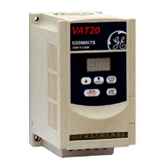
VAT20
Advertisement
Table of Contents

Related Manuals for GE VAT20 Series


Summary of Contents for GE VAT20 Series
- Page 1 GE Industrial Systems AC SPEED CONTROL EQUIPMENT VAT20 1ph, 200V-240V System, 0.2-0.75kW / 1/4-1HP 1ph/3ph, 200V-240V System, 1.5-2.2kW / 2-3 HP 3ph, 380-460V System 0.75-2.2kW / 1-3 HP INSTRUCTION MANUAL --------------------------------- NOTICE ------------------------------------------ Read this manual thoroughly before using the VAT20, and store in a safe place for reference.
-
Page 2: Table Of Contents
Table of Contents Foreword..................1 Chapter 1 Safety Precautions 1. Precautions of operation......... 2 2. Precautions of operation environment ....4 Chapter 2 Hardware Instruction and Installation 1. Operation Environment........... 5 2. Model No. Instructions ..........6 3. Specifications ............7 4. -
Page 3: Foreword
PCB of the inverter. 2. Examination before installation Every GE Power Controls inverter has been fully tested and examined before shipment. Please carry out following examination procedures after unpacking your inverter. Check to see the model number of the inverter. It should be the one that you ordered. -
Page 4: Chapter 1 Safety Precautions
Chapter 1. Safety Precaution 1. Precautions of operation Before turning ON power CAUTION Choose appropriate power source with correct voltage setting as the input voltage specification of the inverter. WARNING Special care must be taken while wiring the primary circuitry panel. The L1 and L2 terminal must be connected to input power source and must not be mistakenly connected to T1, T2 or T3 terminal. - Page 5 Under Operation WARNING Do not use a separate device to switch ON or OFF motor during operation. Otherwise, the inverter may experience an over-current breakdown. WARNING Do not remove the front cover of the inverter when the power is ON to avoid personnel injury caused by electrical shock.
-
Page 6: Precautions Of Operation Environment
2. Precautions of operation environment Avoid direct sunlight Keep away from Keep away from oil corrosive gas or liquid grease and gas Keep away where rain or Avoid metal dust and Keep away from salty dripping water may get dusty environment environment into the inverter Avoid where environment... -
Page 7: Chapter 2 Hardware Instruction And Installation
Chapter 2. Hardware Instruction and Installation 1. Operation Environment The installation site of the inverter is very important. It relates directly to the functionality and the life span of your inverter. Please check the installation to meet the following requirements: Mount the unit vertically Environment temperature: -10 C ~ +50... -
Page 8: Model No. Instructions
2. Model No. Instructions ß MODEL: U20N0K7S (for example) Inverter Model Input Power Rating ß I/P: AC 1PH 200 ~ 240V 50/60 Hz ß O/P: AC 3PH 0 ~ 240V 1.6KVA 4.2A Output Rating Series Power Voltage KW Power Option Rated N: 200V, 1ph 0K2: 0.2kW... -
Page 9: Specifications
3. Specifications Basic Specification, 200V Series Model No: VAT20- U20N0K2_ U20N0K4_ U20N0K7_ U20N1K5_ U20N2K2_ Suitable Motor Power Rating (KW) 0.75 Motor HP Rated Current A 10.5 Capacity KVA 0.53 0.88 Weight (Kg ) 0.76 0.77 1.66 1.76 Input Voltage Max. Single phase (and Three phase for 1.5 and 2.2kW only) 200-240V (+10% -15%) , 50/60Hz (+/-5%) Output Voltage Max. - Page 10 Functional Specification Type drive VAT20 CPU version 1.6 CPU Version from 1.9 (Check function F_29) (Check function F_29) Input Signal Type PNP type (SOURCE) input Control Method Sinusoidal wave PWM control Freq. Range 0~120 Hz 0~200 Hz Frequency Resolution Digital : 0.1Hz(0~99.9Hz) 0.1Hz(0~99.9Hz) 1Hz(100~120Hz)
-
Page 11: Wiring
4. Wiring Molded-Case Circuit Breaker / Magnetic Contact GE Power Controls maintenance and service do not apply to damage caused by following situation: (1) Damage to the inverter caused by the lack of appropriate molded-case circuit breaker or when a circuit breaker with too large of capacity is installed between the power supply and the inverter. - Page 12 Application and precautions of Peripherals Power Source Power supply Apply the power source at the correct rated voltage to prevent from damaging the inverter. A Power Disconnect or Circuit breaker must be installed between Molded-case the AC power supply and the inverter. circuit breaker or ground fault Molded-case circuit breaker:...
- Page 13 External wiring should be carried out in accordance with following requirement. Check and reassure the wiring is correct after the wiring is complete. (Do not utilize the control circuitry buzzer to check the wiring.) EMI connecting: It is very important that the connections between the inverter, the shielded motor cable, and the EMI filters are tested as follows.
- Page 14 Class A, Industrial Environment (only for drives built-in with EMC class A filter (U20----S) When the distance between the inverter and motor is longer than 100m, connection wire should be carefully chosen to reduce the wiring resistance below 3% and the voltage drop (V) = v 3 x Wire resistance (Ω/km) x wire length (m) x current x 10 (B) Control circuitry wiring must be separated terminated and away from the primary power circuitry and other high-voltage or large-current power lines to avoid noise interference.
- Page 15 (a)good (b) good (c) not good (D) Wire specification Choose appropriate wire with correct diameter for primary power circuitry and control circuitry in accordance with electricity regulations. (E) Upon completion, check out to reassure the wiring correctness, broken wires, and secure terminal screws.
- Page 16 VAT20 series inverter terminal descriptions Primary circuitry terminal black ( TM1 ) descriptions Terminal symbol Function description L1/L (R) Primary power source input to drive Single phase (1ph) drives: L1, L2 or L, N L2 (S) Three phase (3ph) drives:...
-
Page 17: Dimensions & Terminal Block Layout
SW1 function description SWITCH 1 External signal type 0~20mA analog signal ( When Fn11 set to 1 ) 4~20mA analog signal ( When Fn11 set to 2 ) 0~10 VDC analog signal ( When Fn11 set to 1 ) Dimensions and terminal block layout Frame 1: U20N0K2, U20N0K4, U20N0K7 Unit (mm) - Page 18 Frame 2: U20N1K5, U20N2K2, U20X0K7, U20X1K5, U20X2K2 3X O 4.5 GROUND Unit:mm LENGTH MODEL 143.1 127.5 U20N1K5, N2K2 U20X0K7, X1K5, X2K2 171.7...
- Page 19 Dimensions & Installation of class B Filter(U20AF0K7) M4x14L Inverter with class B filter (U20AF0K7) mounted. Inverter with class B filter (U20AF0K7) & Din rail (U20AR0K7) mounted.
- Page 20 Mounting instructions Din rail (U20AR0K7) mounting diagram Step1- Aim and insert the 4 retention ribs of U20AR0K7 at the 4 holes in rear panel of VAT20 . Step1- Use small screw Step2- driver inserting Inserting hole Push the the middle rib of middle rib U20AR0K7 U20AR0K7 and...
- Page 21 DIN Rail Installation Mounting clamp and 35mm width rail must be used to install VAT20 on the rail. Install VAT20 Dismounting VAT20 Pull mounting plate Mounting plate Screwdriver First place the groove on the back of module on the upper edge of din rail , 1 Pull the mounting plate downward.
-
Page 22: Chapter 3 Software Index
Chapter 3. Software Index 1. Control Panel Instructions POWER LED DATA STOP CAUTION Do not operate keypad by screwdriver or other sharp-ended tool to avoid damaging keypad. Brief keypad operation flowchart (FREQ) V 1 (FREQ) (READ) DATA F ×× ××× F ××... -
Page 23: List Of Parameters
2. List of Parameters Function Function Description Unit Range Default Note Accelerate time 0.1Sec 0.1 ~ 999 S *1*3 Accelerate / Decelerate Time Decelerate time 0.1Sec 0.1 ~ 999 S *1*3 0: Forward / Stop, Reverse / Stop 0 ~ 1 Operation mode 1:Run/Stop, Forward / Reverse Motor direction... -
Page 24: Parameter Function Description
3. Parameter function description Fn_00 Factory adjustment parameter. Do not change. Fn_01 : Accelerate time = 0.1 ~ 999 sec Fn_02 : Decelerate time = 0.1 ~ 999 sec 1. Accelerate/decelerate time calculation formula: Accelerate time = Fn_01 x Setting Frequency 60 Hz Decelerate time = Fn_02 x Setting Frequency... - Page 25 Fn_04 : Motor rotation direction setting = 0 : forward 1 : reverse Although there is no Forward/Reverse push button on the digital control panel, it is possible to adjust forward/reverse function by changing Fn_04 setting. NOTE: When Fn_22 =1: Reverse disabled, the Fn_04 can not be set to 1. Then keypad indication would display “LOC”.
- Page 26 Fn_06 : frequency upper limit = 1 ~ 120 Hz or 200Hz (*) Fn_07 : frequency lower limit = 0 ~ 120 Hz or 200Hz (*) (*)Only for drives with CPU version from 1.9 ( Check function F_29) Fn_06 (freq. Upper limit) Internal frequency signal...
- Page 27 Fn_11 : Frequency control = 0 : Frequency instruction is setup by Keypad = 1 : Frequency instruction is setup by VR or analog signal on TM2 ( 0 ~ 10V / 0-20mA ) = 2 : Frequency instruction is setup by VR or analog signal on TM2 ( 4-20mA ) NOTE 1: When Jog frequency or Sp1 frequency is...
- Page 28 Fn_14 Stopping method = 0 : decelerate stop 1 : free run stop Fn_15 DC braking time = 0 ~ 25.5 sec Fn_16 DC braking starting frequency = 1 ~ 10 Hz Fn_17 DC braking level = 0 ~ 20 % If Fn_14 = 0 When the inverter receive the stop instruction, it decelerate to the frequency setup by Fn_16 and then output voltage level setup in the Fn_17;...
- Page 29 Fn_05 = 4,5,6 Fn_05 = 1,2,3 60 Hz standard motor 50 Hz standard motor Derating % Minute Derating Decay 20 60 (Figure 2) 50 (Figure 1) (Figure 3) 100 150 Percentage of Current Fn_19: Multifunction input terminal 1 function = 1~5 or 6 (*) Fn_20: Multifunction input terminal 2 function = 1~5 or 6 (*) (*)Only for drives with CPU version from 1.9 ( Check function F_29) Fn_19, Fn_20 =1 : JOG...
- Page 30 Fn_19, Fn_20 =4: External Base Block ( immediate shut off ) When the external base block signal is activated, the inverter output will be immediately shut off (ignoring setting in Fn_14) and flash b.b. After the base block signal is deactivated, turn the RUN switch OFF and then ON again (Fn_10 = 1) or push the RUN key (Fn_10=0), the inverter will restart from the starting frequency.
- Page 31 Fn_24: Number of Auto-restart times = 0~5 1. When Fn_24 = 0, the inverter will not try to restart. 2. When Fn_24 > 0 , the inverter will resume operation via SPEED SEARCH at approximately 0.5 second after a function trip. After that, the inverter will accelerate or decelerate to current frequency setting.
- Page 32 Fn_30: Fault trace, (Last three faults) 1. Fault trace : indicate the sequence of the occurrence of malfunctions by the location of decimal point. x.xx indicate a recently happened malfunction. xx.x indicate the last malfunction that happened. xxx. indicated the earliest malfunction in the record. 2.
-
Page 33: Malfunction Indication And Countermeasure
4. Malfunction Indication and Countermeasure 4.1 Manual reset inoperative faults INDICATION CONTENT POSSIBLE CAUSE COUNTERMEASURE Program error Outside noise interference Place a RC surge absorber in parallel with noise generating magnetic contact EEPROM error EEPROM defective Replace EEPROM Voltage too 1. - Page 34 4-3 Manual Reset and Auto-Reset Operative faults INDICATION CONTENT POSSIBLE CAUSE COUNTERMEASURE Transient 1. Motor coil short -circuit with 1. Examining motor over-current external casing 2. Examining wiring starting machine 2. Motor connection wire 3. Replace transistor module short-circuit with grounding 3.
- Page 35 4-4 Other indications INDICATION CONTENT DESCRIPTION Zero Speed When Fn_11 = 0, Fn_7= 0 and frequency setting < 1 Hz Stopping When Fn_11 = 1, Fn_7<(Fn_6/100), and frequency setting <(Fn_6/100) Keypad The inverter setup to external operation (Fn_10=1). If the STOP emergency stop key in the keypad is pressed at the middle of operation, the inverter stop according the setting in Fn_14 and flash SP2 after...
-
Page 36: General Troubleshooting Method
5. General Troubleshooting Method ABNORMALITY CHECK POINT COUNTERMEASURE Is power source voltage delivered into L1, Check if the power source switched on. L2 terminal (is the charging indicator Turn power source OFF and then ON illuminated)? again. Reconfirm the power voltage level. Check to see if the mounting screw secured. - Page 37 Simple VAT20 Troubleshooting Procedure VAT20 INV Malfunction Clearly defined malfunction Y E S Examining component with Sign of burn Any sign of burnt sign of burnt or breakage or breakage of breakage? Y E S Indication of ABNORMAL Is the primary Replace DM abnormality circuitry DM normal?
- Page 38 ( Continued ) Examining Inverter parameters Carry out parameter initialization Designate operation control method Frequency instruction setting Does the controller displays Replace control board frequency setting? Is there voltage output on Replace control board UVW terminals? No, The problem Is replacing is not corrected Connect to motor and control board correct...
- Page 39 Error handling of malfunction indication of OC.OL When inverter display malfunction indication OC.OL. Is the primary ABNORMAL Replace I.G.B.T. circuit I.G.B.T. normal? NORMAL Is the appearance Replace defective PCB normal? Switch ON power supply Is there any malfunction indication Is the current ABNORMAL Input operation detector normal?
- Page 40 Error handling of malfunction indication of OV.LV Inverter display OV.LV Is there any abnormal breakage Replace defective board on appearance Switch ON power supply Is there any Replace control board malfunction indication Input operation instruction Input frequency instruction Is the output Replace control board frequency of controller displayed...
- Page 41 (1). Motor inoperative Is the circui t breaker (MCCB) switched ON? Can not Wiring short-circuit Can you switch ON the MCCB? Is the • Power source voltage between ABNORMAL abnormality L1-L2 power input terminals • Poor wiring normal? Normal (within +/- 10% of nominal value) VAT20 malfunction Is Power LED off ? Place the operation...
- Page 42 (2). Motor over-heat Reduce loading there over-loading Enlarge VAT20 and condition or the load current exceeds rated Motor capacity current? Operate at low Select another motor speed for a long time? Is the voltage level between VAT20 malfunction T1-T2, T2-T3, and T3-T1 normal? Is there Remove obstacle...
- Page 43 Routine examination and periodical examination Inverter requires routine and periodical examination and maintenance for a more stable and safer operation. Refer to following table for required examination item for a more stable and safer operation. Carry out examination after the “ Power LED ” indicator goes off for 5 minutes to prevent the maintenance personnel injury caused by the remaining charges in the capacitor of inverter.
-
Page 44: Chapter 4 Maintenance And Peripherals
Chapter 4. Maintenance and Peripherals Maintenance and Examination Frequent examination and maintenance is not required for VAT20. To maintain appropriate reliability for a long term of time, please proceed with following periodical examination. Remember to turn off power supply and wait till the Power LED went off before proceed. (Due to the large amount of remaining charges in the internal capacitors.) Clean out internal dust and dirt. - Page 45 Voltage Current Measurement The voltage and current measurement on the primary and secondary side may be different for the reason of the instrumentation and the high frequency wave. Refer to following diagram for measurement of single phase units. Different kinds of instrument NOTE Measurement...
- Page 46 Input AC Reactor Specification (1*) VAT20 Model AC Reactor (2*) AC Reactor (3*) VAT20 Model AC Reactor (2*) AC Reactor (3*) U20N0K2 ACR3A7H0 37G00204 U20X0K7 ACR3A8H1 37G00201 U20N0K4 ACR8A2H5 37G00204 U20X1K5 ACR4A5H1 37G00402 U20N0K7 ACR12A2H5 37G00401 U20X2K2 ACR6A3H4 37G00402 1ph, U20N1K5 ACR18A1H3 37G00801 3ph, U20N1K5...
Need help?
Do you have a question about the VAT20 Series and is the answer not in the manual?
Questions and answers