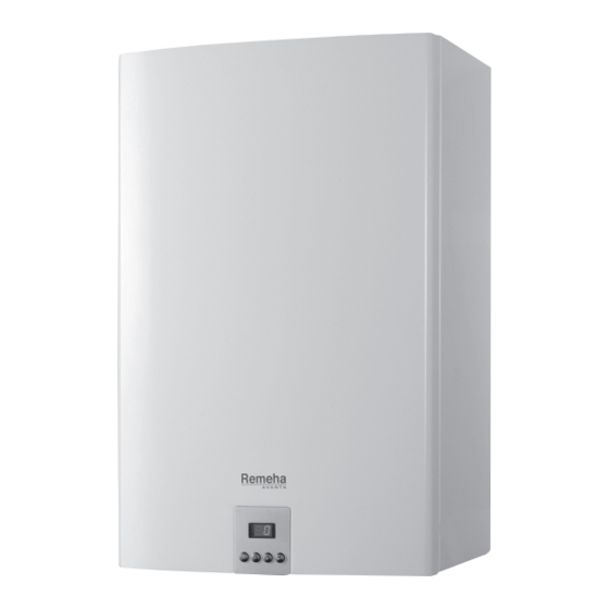
REMEHA Avanta 12v Installation & Service Manual
Avanta range
Hide thumbs
Also See for Avanta 12v:
- Users operation instructions & important warranty information (12 pages) ,
- User manual (3 pages)
Table of Contents
Advertisement
Quick Links
Advertisement
Table of Contents

Related Manuals for REMEHA Avanta 12v


Summary of Contents for REMEHA Avanta 12v
- Page 1 Installation & Service Manual Remeha Avanta Range 12v I 18v I 24v...
-
Page 2: Table Of Contents
Mounting the Remeha Avanta ........ - Page 3 Remeha factory test ........
-
Page 4: Introduction
Remeha Avanta INTRODUCTION The Remeha Avanta is a series of wall mounted high-efficien- cy fully condensing central heating boilers, for open vented systems These technical instructions contain useful and important infor- mation for the correct installation, operation and maintenance of the Remeha Avanta boiler. -
Page 5: Safety
Safety during installation, inspection and maintenance Under the Gas Safety (Installation & Use) Regulations 1998, the Remeha Avanta, in common with all gas appliances, must be installed by a competent person in accordance with that regulation. Statutory regulations, in any country, cannot be overridden by any of the notes or instructions from the manufacturer. - Page 6 Remeha Avanta For any issues or circumstances not addressed within these instructions, please call our After Sales Department 0118 9743070 Remeha Avanta 12v - PIN: 0063BQ3009 Remeha Avanta 18v - PIN: 0063BQ3009 Remeha Avanta 24v - PIN: 0063BQ3009 Gas Council numbers:...
-
Page 7: Installation
Assembly Instructions supplied with these accessories. Mounting the boiler Packed in the box with the Remeha Avanta box is this Instal- lation and Service manual. Read instructions and remarks carefully. This section includes the guidelines and instructions for the connection of gas, water, electricity, safety devices, the fig. -
Page 8: Dimensions And Connection Points
(standard overflow pipe size) • Based on the guidelines and the required installation space, determine where to mount the Remeha Avanta. • In determining the boiler position, consider carefully the flue outlet position and any pluming consequences. fig. 04... -
Page 9: Mounting The Remeha Avanta
2.2.3 Mounting the Remeha Avanta • Remove template from the box. • Using the template determine and mark the position of the mounting bracket and flue outlet. • Drill the (Ø 8 mm) holes. • Fit the (Ø 8 mm) plugs. -
Page 10: Pressure Loss Of The Boiler
Remeha Avanta Pressure Loss Graph 2.3.3 Pressure loss of the boiler 2.3.4 Open-Vented System The feed and expansion tank must be situated at a minimum height of 1 metre and a maximum height of 30 metres above the boiler to provide the correct operating head pressure. -
Page 11: Water Treatment
2.3.7 Water treatment If used correctly water treatment can improve the boilers efficiency and increase the anticipated life expectancy of the boiler. For further information a special document “Quality requirements CH water” is available from Broag. As most systems contain a variety of metals, it is considered good practice to provide some form of water treatment in order to prevent or reduce the following: •... -
Page 12: Safety Valve Discharge
Remeha Avanta 2.3.8 Safety valve discharge A pressure relief safety valve is not needed for Open-Vented systems. 2.3.9 Draining Provision Drain points must be provided at all the low points of the system to ensure that the entire system can be completely drained. -
Page 13: Connecting Condensate Drain
2.3.12 Connecting condensate drain • Connect the condensate drain outlet to a suitable waste water drain point using acid resisting pipe work (i.e. - ¾” overflow). To enable the siphon in the boiler to be removed / serviced, the connection should not be a permanent one (i.e. -
Page 14: Connecting The Gas Supply
Engineer and in accordance with BS6891. Flue terminal and air supply connections The Remeha Avanta is only suitable for room sealed operation fig. 11 Connecting gas supply with a standard concentric connection 60/100 mm Ø or the 59970.LT.GB.W7H.035... - Page 15 600 mm No flue must penetrate area within dotted lines 600 mm round roof light 2000 mm fig. 12 Flue terminal positions LT.AL.W7H.000.020 Dimensions Terminal location Minimum distance (in mm) to terminal (room sealed) Directly below an opening, air brick, opening window, etc.
-
Page 16: Room Sealed Flue
Remeha Avanta 2.5.2 Room sealed flue See table 02 for the maximum pipe length of flue ducts and air supply pipes for this ‘room sealed’ application. It is not necessary to provide combustion air to the room or internal space in which the boiler is installed. -
Page 17: Electrical Connection
• X1, X2, X4, X5, X6 and X7 terminal strip; • 230 V supply cable connection. 2.6.1 The control unit The Remeha Avanta has an electronic regulation and control unit with an integrated ionisation flame detector. The heart of fig. 14 Electrical components with live 230 V the boiler control unit is a microprocessor, the ‘abc... -
Page 18: Connecting External Controls
Remeha Avanta The output of the Remeha Avanta can be controlled in the fol- lowing ways: On/off control – volt free switching - The boilers internal control will modulate the output to achieve the flow tempera- ture set point of the boiler. This contact is on the X9 terminal strip (low voltage only). -
Page 19: Connecting An On/Off Control - Room Temperature (Volt Free Switching)
2.7.1 Connecting an on/off control – room temperature (volt free switching) The Remeha Avanta can be connected to a 2-wire on/off ther- mostat, such as the Remeha Celcia 10. Terminal Mount the thermostat in a reference room (usually the living Block X9 room). -
Page 20: Connecting A Time Control Using An External 230 V Clock
X2 terminal strip and a Celcia 15 connected to connectors 7 and 8 of X9 terminal strip (remove existing link), the Remeha Avanta will provide room compen- sated heating and time control over CH and DHW. -
Page 21: Connecting A Modulating Control - Room Or Outside Compensation
® bles our modulating range of OpenTherm room controls (e.g. ® Terminal the Remeha Celcia 15 or 20) to be connected without any fur- Block X9 ther modifications. • Mount the control in a reference room (usually the living room). -
Page 22: Connecting The Dhw Sensor/Thermostat
Remeha Avanta Terminal 2.7.6 Connecting the DHW sensor/thermostat Block X9 • If an external DHW calorifier is being used with the Avanta system boiler a DHW control sensor or volt-free thermo- stat can be connected to connectors 3 and 4 of the X9 terminal strip. -
Page 23: Connecting An External Interlock
2.7.9 Connecting an external interlock The Remeha Avanta is supplied with an external interlock function. A volt free switching device (i.e. external gas pres- Exist External interlock (volt free) -
Page 24: Connecting A Pc/Pda
Remeha Avanta 2.7.11 Connecting a PC/PDA Using the optional Recom interface package a PC or PDA can be connected to the X10 “telephone connector”. Using the Recom PDA service software you can load, change and down- load various boiler settings and readings. See the user instruc- tions supplied with the software/hardware. -
Page 25: Wiring Diagram
Wiring diagram Power supply 230V, 50Hz GN/YW GN/YW 4 5 1 1 2 3 4 5 1 2 3 4 1 2 3 4 1 2 3 1 2 3 1 2 3 4 1 2 3 4 5 6 7 8 1 10 COMM. -
Page 26: Commissioning
2.10 Commissioning 2.10.1 Control Panel The control panel of the Remeha Avanta has 4 function keys and a LED display. The function keys are used to read or change the settings and temperatures. 1 = display 2 = [reset] key... - Page 27 1. Isolating the power supply and opening the front cover 230 V • Switch off the boiler at the fused spur and remove the fuse; • Remove the front panel - release the two screws at the bot- tom of the front panel, pull the bottom of the panel towards you from the centre, making sure that the plastic catch is released from the central display.
- Page 28 Remeha Avanta • Open the boiler gas valve and check the static pressure to the boiler at the measurement point (C) on the gas block. • The boiler has been factory tested for natural gas at 20 mbar. • The minimum gas inlet pressure is 17 mbar for natural gas •...
- Page 29 3. Switching the boiler on and setting the controls • Replace the fuse and switch on the 230 V power supply. • Set the controls to heat demand. • When 230v power is first applied to the boiler or after the 230v supply has been isolated for maintenance the boiler will not start until it has fully completed its venting cycle –...
- Page 30 Remeha Avanta • Unscrew the flue gas sampling cap and connect the flue gas analyser. • Set boiler to full load: Press the [enter]- key, keep it pressed and also press the [+]-key until h3 appears in the display; full load has been set.
- Page 31 59970LTGBW7H019 The boiler is now ready for operation. The Remeha Avanta is delivered pre-tested and operating parameters set up with standard factory settings to suit the most common systems. These setting can be adjusted to suit specific site conditions but must not be changed without refer-...
-
Page 32: Normal Start-Up Procedure
Remeha Avanta 7. Instructing the user • It is the responsibility of the installer as part of the com- missioning procedure to instruct the user in the day to day operation of the boiler and controls fitted to the system and to hand over the completed Boiler Benchmark Check- list at the back of this manual. -
Page 33: Read Out Settings
After any error é1, é2, é7, é10 or é13 ; the 3 minute venting cycle will run first before starting the boiler. • Checking CH function; - Ensure the time control is in the CH on position - Set the room thermostat on a high demanding temperature and, the display shows [1 ;... -
Page 34: Adjust The Boiler According To The System
The operating parameters of the Remeha Avanta have been factory set to suit most systems. However it is possible to adjust some of the parameters to enable the Remeha Avanta to operate more efficiently to match specific system designs and site conditions. These parameters are split into two spe- cific sections 1. - Page 35 Minimum fan speed Do not change (natural gas) Minimum fan speed 10 - 40 (propane) Starting fan speed Do not change (natural gas) Starting fan speed (pro- Do not change pane) Pump setting CH Do not change Pump running time after 1 - 99 minutes Connection with Heat 0 = no connection with HRU...
- Page 36 Remeha Avanta The parameters can be changed from the stand-by status as follows: • Press the [enter]-key and briefly the [reset]- key until codes c and 0 appear alternately in the display. • Press the [+]-key until access code 12 is displayed.
-
Page 37: Changing The Maximum Output (Hi) For Ch Operation
15.0 10.0 1000 1500 2000 2500 3000 3500 4000 4500 Fan speed [rpm] fig. 45 Fan speed / boiler input ratio Avanta 12V and 18V T001103 Speed-input ratio 1000 2000 3000 4000 5000 6000 7000 Fan speed [rpm] fig. 46... -
Page 38: 2.10.10 Restore Factory Settings
Remeha Avanta 2.10.10 Restore factory settings The factory settings can be restored in the service level as fol- lows: After parameter p31 has shown, press the [+]-key; d f and xx appear alternately; Press -key; xx appears; Read boiler identification plate for value of d f ; press [+] or [-] key to reach this value;... -
Page 39: Inspection And Maintenance
Engineer with the relevant training and certification (i.e. ACS - IEE registrations etc). Inspection The annual inspection of the Remeha Avanta can be limited to the following checks: - check the flue pipes and air supply pipes for leaks, see par. -
Page 40: Checking The Condensate Siphon
Remeha Avanta 3.1.2 Checking the condensate siphon • Check the condensate siphon. Remove any dirt residues and refill with clean water to the mark. fig. 50 Checking the condensate siphon 59970LTGBW7H0234 3.1.3 Checking the ignition electrode • Check the ionisation /ignition electrode for: - deposits (remove any white deposits with abrasive cloth);... -
Page 41: Checking The Combustion
3.1.4 Checking the combustion • Measure the O percentage and the flue gas tempera- ture at the flue gas sample point. Do this as follows: - heat the water temperature in the boiler to approx. 70°C; - unscrew the top of the flue gas point of measurement; - measure the O percentage and compare this to the check values in table 09. -
Page 42: Maintenance
Remeha Avanta Maintenance To conduct maintenance: Ensure that a service gasket set and new ignition/ionisation electrode is available before carrying out this procedure. • Isolate power supply at the fused spur before carrying out any work on the boiler. - Page 43 2. Maintenance of the ignition/ionisation electrode • Disconnect the earth wire from the electrode mounting plate. • Release the two screws on the electrode and remove the assembly. • Inspect, clean re-gap or replace the electrode, see par 3.1.3. • Do not over tighten the screws when replacing. fig.
- Page 44 Remeha Avanta 4. Maintenance to the burner • Carefully clean the burner with pressured air (do not keep the nozzle to close to the surface). • Visual inspection of the burner for any damages or cracks on the surface. If you see any damages, than replace the burner.
- Page 45 6. Re-Assembling the boiler and checking the combustion • Re-assemble all the components in reverse order. • Remember to connect the fan plug again before it is completely home on the front of the heat exchanger. • Check that the packing between the front plate and the heat exchanger has been fitted correctly.
-
Page 46: Errors
Remeha Avanta ERRORS General The Remeha Avanta has an advanced control unit. The heart of this control unit is a microprocessor, the abc -control which ® both controls and protects the boiler. If an error is detected anywhere in the boiler, it will lock out and an error code will appear in the display. - Page 47 Insufficient water. Check the water level and check for leaks. Check that the pump is working; turn the spindle with a screwdriver, No through flow. if that works but the pump still does not respond, check the wiring; that is in order the pump is faulty. Too much air in the system.
- Page 48 Remeha Avanta Insufficient water. Check the water level and check for leaks. Check that the pump is working; turn the spindle with a screwdriver, No water in the No through flow. if that works but the pump still does not respond, check the wiring;...
-
Page 49: Control Stop Or Lock-Out
The lock-out will disappear once the cause has been removed! Error code memory The Remeha Avanta control unit has an error code memory, in which the last 16 errors are stored. In addition to the error code (é and a number xx). -
Page 50: Error Read Outs
Remeha Avanta 4.4.1 Error read outs • Press the [enter]-key and keep it pressed; • Press the [reset]-key until codes c and 0 appear alter- nately in the display; • Enter the special access code 88 with the [+] or [-]- key;... -
Page 51: Service Parts
General If, following the annual inspection or maintenance any part of the boiler is found to need replacing, use Remeha spare parts only or spare parts and materials recommended by Remeha. If any component is to be replaced and it is covered by the... - Page 52 3001 3004 1002 2018 2019 2016 2014 3006 2020 2004 3009 3003 3010 2029 3008 2028 3011 3012 2021 3005 4012 3002 2023 2024 3012 4003 4011 3004 2025 2027 2023 3015 59970EVGBW7H010b fig. 62 Exploded view Remeha Avanta 59970EVGBW7H010...
- Page 53 Break down parts kit Part No Description Position S100006 Heat exchanger 2001 S62741 Burner 2003 S62743 Electrode ignition/ionisation 2004 S59118 Glass inspection set 2005 S100015 Siphon assembly 2021 S58733 Sensor temperature (2 pcs) 2023 S100011 Fan assembly 3001 S58685 Gas combination block 3005 S100068 Control board...
-
Page 54: Ec Declaration
: Kanaal Zuid 110 Town, Country : Postbus 32, NL-7300 AA Apeldoorn - hereby declares that the appliance(s) : Remeha Avanta 12V, 18V, 24V comply / complies with the specifications of the following EEC directives: EEC Directive: 90/396/EEC applied standards:... -
Page 55: Regulations
- 97/23/EEC Pressure equipment directive (art. 3, sub. 3) Classification type for evacuation of the combustion products; according EN 483 Remeha factory test Before it leaves the factory, each Remeha Avanta boiler is optimally adjusted and tested for: - electrical safety; - CO2- adjustment;... -
Page 56: Technical Specifications And Working Principle
Remeha Avanta TECHNICAL SPECIFICATIONS AND WORKING PRINCIPLE Technical data Appliance type Remeha Avanta General Gas council number 41-288-09 41-288-06 41-288-10 Boiler control modulating or on/off Nominal output Pn (80/60°C, CH) 12.0 17.6 24.7 Nominal output Pn (50/30°C, CH) 13.1 19.0 26.5... -
Page 57: The Boiler Components
11. Control unit Working principle The Remeha Avanta casing serves as a sealed air box, with air drawn in by the fan. On the outlet side of the fan is a ventu- ri, into which a measured quantity of gas is injected based on the volume of air available. -
Page 58: Advanced Boiler Control ('Abc®'-Control)
® 8.3.3 Regulating the water temperature The Remeha Avanta is fitted with an electronic temperature regulator with flow and return temperature sensors. The flow temperature can be set to between 20 and 75°C, see 2.10.8 (factory setting 75°C). The boiler modulates it’s output up and down to match the flow set point from internal or external con- trol. -
Page 59: Efficiency Data And Gas Efficiency Labels
EFFICIENCY DATA AND GAS EFFICIENCY LABELS Annual efficiency 108.7 % in relation to Hi at a load of 30% and a return tem- perature of 30°C. Water-side efficiency 98 % in relation to Hi at full load and an average water tem- perature of 70°C (80/60°C). - Page 60 Remeha Avanta...
- Page 62 Remeha Avanta...
- Page 64 120579-060309 Broag Ltd. Remeha House Molly Millars Lane RG41 2QP WOKINGHAM, Berks. Tel: +44 118 9783434 Fax: +44 118 9786977 © Copyright Internet: uk.remeha.com All technical and technological information contained in these technical instructions, as well as any drawings and technical www.avantarange.com...
Need help?
Do you have a question about the Avanta 12v and is the answer not in the manual?
Questions and answers