
Related Manuals for Keysight Technologies IntegraVision PA2200 Series


Summary of Contents for Keysight Technologies IntegraVision PA2200 Series
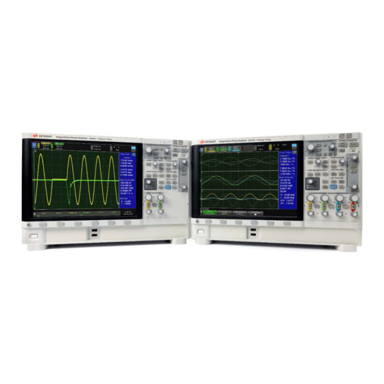
- Page 1 Test Equipment Depot - 800.517.8431 - 99 Washington Street Melrose, MA 02176 - TestEquipmentDepot.com Operating and Service Guide Keysight IntegraVision PA2200 Series Power Analyzers...
-
Page 3: Copyright Notice
No part of this manual may be reproduced in any form or by any means (including electronic storage and retrieval or translation into a foreign language) without prior agreement and written consent from Keysight Technologies, Inc. as governed by United States and international copyright laws. -
Page 4: Warranty
Technology Licenses The hardware and/or software described in this document are furnished under a license and may be used or copied only in accordance with the terms of such license. Keysight IntegraVision PA2200 Series Power Analyzers Operating and Service Guide... -
Page 5: U.s. Government Rights
Declarations of Conformity for this product and for other Keysight products may be downloaded from the Web. Go to http://regulations.corporate.keysight.com/DoC/search.htm and click on “Declarations of Conformity.” You can then search by product number to find the latest Declaration of Conformity. Keysight IntegraVision PA2200 Series Power Analyzers Operating and Service Guide 3... -
Page 6: Safety Information
A WARNING notice denotes a hazard. It calls attention to an operating procedure, practice, or the like that, if not correctly performed or adhered to, could result in personal injury or death. Do not proceed beyond a WARNING notice until the indicated conditions are fully understood and met. Keysight IntegraVision PA2200 Series Power Analyzers Operating and Service Guide... -
Page 7: Safety Symbols
This equipment is Class A suitable for professional use and is for use in electromagnetic envir- onments outside of the home. Contains more than the maximum concentration value (MCV) of one or more of 6 specified haz- ardous substances; 40 Year EPUP. Keysight IntegraVision PA2200 Series Power Analyzers Operating and Service Guide 5... - Page 8 Do not install substitute parts or perform any unauthorized modification to the product. Return the product to a Keysight Technologies Service facility for service and repair to ensure that safety features are maintained.
- Page 9 1000 VAC. Do not use this instrument for per- forming measurements in Measuring Category III or IV environments. See the section titled “IEC Measurement Category II” for further information. Keysight IntegraVision PA2200 Series Power Analyzers Operating and Service Guide 7...
- Page 10 For current measurements, assure that all leads and connectors are suit- ably insulated and rated for the highest current and voltage that is applied to any cur- rent measuring terminal on any channel. Keysight IntegraVision PA2200 Series Power Analyzers Operating and Service Guide...
- Page 11 Measurement Limits defined in the following section. Measurement Limits This is a sensitive measurement apparatus by design and may have some performance loss when exposed to ambient continuous electromagnetic phenomenon. Keysight IntegraVision PA2200 Series Power Analyzers Operating and Service Guide 9...
- Page 12 Limits are not exceeded. To ensure safe operation of the instrument, do not exceed the Measurement Limits shown on the rear panel, and defined as follows: PA2201A Measurement Module Markings Keysight IntegraVision PA2200 Series Power Analyzers Operating and Service Guide...
- Page 13 The Measurement Limit from the center conductor to the outer conductor is 10 VAC rms or VDC. The Measurement Limit from either the center conductor or the outer conductor to the chassis is 1000 VAC rms or VDC. Keysight IntegraVision PA2200 Series Power Analyzers Operating and Service Guide 11...
- Page 14 The outer shell of the Ref In, Trig In and Trig Out SMA connectors are connected directly to chassis. The maximum voltage that may be applied to the center conductor of these terminals with respect to the outer shell/chassis is 5 V. Keysight IntegraVision PA2200 Series Power Analyzers Operating and Service Guide...
- Page 15 Always allow adequate time for circuits being measured to fully de-energize after remov- ing power from these circuits. Do not rely on the reported readings from the instrument to determine whether a circuit is de-energized. Keysight IntegraVision PA2200 Series Power Analyzers Operating and Service Guide 13...
- Page 16 You can verify that the instrument cor- rectly senses the position of the shutter by running the ‘Interactive Self Test’ found under [Utility] > Service on the front panel interface. Keysight IntegraVision PA2200 Series Power Analyzers Operating and Service Guide...
- Page 17 I50A inputs when using the Internal Current Measurement inputs. The proper input must be selected via the front-panel interface. Never apply signals to I2A and I50A sim- ultaneously, as this may cause incorrect measurements. Keysight IntegraVision PA2200 Series Power Analyzers Operating and Service Guide 15...
- Page 18 Always allow adequate time for circuits being measured to fully de-energize after remov- ing power to these circuits. Do not rely on the reported readings from the instrument to determine whether a circuit is de-energized. Keysight IntegraVision PA2200 Series Power Analyzers Operating and Service Guide...
-
Page 19: Instrument Service Tasks
You should run Hardware Self Test after experiencing abnormal operation, for diagnostic information, or to verify proper operation after a repair. A successful Hardware Self Test provides an 80% confidence level that the instrument is operating properly. Keysight IntegraVision PA2200 Series Power Analyzers Operating and Service Guide 17... -
Page 20: Front-Panel Self Test
To clean the instrument, disconnect power and all connections to the instrument. Then clean the external surfaces with a soft cloth slightly dampened with a solution of mild detergent and water. Ensure that the instrument is completely dry before reconnecting it. Keysight IntegraVision PA2200 Series Power Analyzers Operating and Service Guide... -
Page 21: Getting Started
Keysight IntegraVision Series Power Analyzers Operating and Service Guide Getting Started Inspect the Package Contents Learn the Front Panel Learn the Rear Panel Use the Touchscreen Access the Built-In Quick Help Softkey Menu Overview... -
Page 22: Inspect The Package Contents
– Power cord (destination country determines specific type) – Current connectors (one per channel) – Certificate of calibration – Safety information document – Getting Started sheet – AC Power Source Analyzer ROHS Addendum Keysight IntegraVision PA2200 Series Power Analyzers Operating and Service Guide... -
Page 23: Learn The Front Panel
Learn the Front Panel The color display (800x600 pixels) is the heart of the power analyzer's user inter- face. Configure the horizontal axis and navigate through the waveform. Horizontal Controls Keysight IntegraVision PA2200 Series Power Analyzers Operating and Service Guide 21... - Page 24 Math Waveforms Math Operators Math Transforms FFT Measurement Reference Waveforms Specify, adjust and annotate the way the waveform is displayed. Enable or disable the touchscreen for enhanced usability. Display Settings Keysight IntegraVision PA2200 Series Power Analyzers Operating and Service Guide...
- Page 25 ([1], [2], [3], or [4]) and then pressing the Filter softkey. Channel Controls [Wiring] Key: Channel Skew [Wiring] Key: Channel Grouping To Filter Incoming Signals Phasor Diagrams Keysight IntegraVision PA2200 Series Power Analyzers Operating and Service Guide 23...
-
Page 26: Tilt The Instrument For Easy Viewing
Use the two USB ports to save and load files. Tilt the Instrument for Easy Viewing Move the support feet on the bottom of the front of the instrument (both sides) into the tilted position as shown below. Keysight IntegraVision PA2200 Series Power Analyzers Operating and Service Guide... -
Page 27: Learn The Rear Panel
Connect your voltage signal here. The maximum input range is 1000 V. Connect a voltage signal from a current transducer here (shown on channel 1). The maximum input range is 10 V. Keysight IntegraVision PA2200 Series Power Analyzers Operating and Service Guide 25... - Page 28 Connect power here. This may be 100 to 240 VAC at 50 to 60 Hz or 100 to 120 VAC at 400 Hz. The maximum power is 140 VA for the PA2201A and 170 VA for the PA2203A. Keysight IntegraVision PA2200 Series Power Analyzers Operating and Service Guide...
-
Page 29: Use The Touch Screen
When the lower half of the icon is highlighted, you can drag the waveform horizontally. When the top half of the icon is highlighted, you can drag your finger across the touchscreen to draw a rectangle, as shown below. Keysight IntegraVision PA2200 Series Power Analyzers Operating and Service Guide 27... - Page 30 Note that you can also select Horizontal Waveform Zoom to zoom in horizontally, but not vertically. Press Undo to revert to the previous vertical and horizontal zoom levels. Keysight IntegraVision PA2200 Series Power Analyzers Operating and Service Guide...
-
Page 31: Select Sidebar Information Or Controls
Select Sidebar Information or Controls Press the blue menu button near the upper right corner of the display to show a list of sidebars. Keysight IntegraVision PA2200 Series Power Analyzers Operating and Service Guide 29... - Page 32 The sidebar that you select (Ctrls, in the image below) will appear on top of the previous one. Keysight IntegraVision PA2200 Series Power Analyzers Operating and Service Guide...
-
Page 33: Drag Cursors
Press this button to open a Help control. Pressing the Help control will open a help window describing the sidebar. Drag Cursors Drag the name handles of cursors to position them. Keysight IntegraVision PA2200 Series Power Analyzers Operating and Service Guide 31... -
Page 34: Touch Softkeys And Menus On The Screen
Some softkeys open alphanumeric dialogs that let you touch to enter names. Simply press the keys on the keyboard, and then press OK when done. Note that the Shift key allows you to access symbols, such as !, @, #, and $. Keysight IntegraVision PA2200 Series Power Analyzers Operating and Service Guide... -
Page 35: Change Waveform Offsets By Dragging Ground Reference Icons
Touch menu items and submenu items to access menus and additional controls. Touch left side controls to perform instrument operations. Keysight IntegraVision PA2200 Series Power Analyzers Operating and Service Guide 33... -
Page 36: Turn Channels On-Off And Open Scale-Offset Dialogs
Access the Horizontal Menu and Open the Scale-Delay Dialog Touch "H" to access the Horizontal Menu. Touch the horizontal scale and delay values to access a dialog for changing them. Keysight IntegraVision PA2200 Series Power Analyzers Operating and Service Guide... -
Page 37: Modify Triggering
Touch "T" to access the Trigger Menu. This is equivalent to pressing the [Trigger] key on the front panel. Touch the trigger level value(s) to access a dialog for changing the level(s). Touch "Auto" or "Trig'd" to quickly toggle the trigger mode. Keysight IntegraVision PA2200 Series Power Analyzers Operating and Service Guide 35... -
Page 38: Access The Built-In Quick Help
The About IntegraVision softkey provides information about your instrument, including serial number, firmware revision, and where to download the latest firmware. Keysight IntegraVision PA2200 Series Power Analyzers Operating and Service Guide... -
Page 39: Context-Sensitive Help
Press this button to open a Help control. Pressing the Help control will open a help window describing the sidebar, as shown below. Keysight IntegraVision PA2200 Series Power Analyzers Operating and Service Guide 37... -
Page 40: Softkey Menu Overview
Channel 1, Channel 2, Channel 3, Channel 4, Wiring (PA2203A) Phase Names, Channel Skew Channel 1, Channel 2, Channel 3, Channel 4 Filter (PA2203A only) Phasor Diagram, Source, Volts /, Amps / Phasor (PA2203A only) Keysight IntegraVision PA2200 Series Power Analyzers Operating and Service Guide... -
Page 41: Channel Configuration
Keysight IntegraVision Series Power Analyzers Operating and Service Guide Channel Configuration Voltage and Current Signals Channel Controls Horizontal Controls Auto Scale Channel Skew Channel Grouping... -
Page 42: Voltage And Current Signals
The instrument achieves the HV configuration by inserting an amplifier into the signal path and spreading the information content over more bits of the analog-to-digital converter. In the example below, enabling HV reveals the noise on the sine wave. Keysight IntegraVision PA2200 Series Power Analyzers Operating and Service Guide... -
Page 43: Configure An External Current Probe
Configure an External Current Probe The IntegraVision PA2200 Series power analyzers support several types of current probes, including external current shunts, current clamps, current transformers, Hall effect probes, Rogowski coils, and the Keysight N2780B, N2781B, N2782B, and N2783B current probes. - Page 44 HV reveals the noise on the sine wave. Note that when you calculate measurement uncertainty, you should refer to the probe's datasheet and add the probe's uncertainty to the measurement uncertainty of the power analyzer. Keysight IntegraVision PA2200 Series Power Analyzers Operating and Service Guide...
-
Page 45: Configure An Internal Current Measurement
Use only the specified mating connector. Do not use unspecified mating connectors, including mating connectors with strain reliefs such as the part shown below. Unspecified mating connectors could expose the user to hazardous voltages. Keysight IntegraVision PA2200 Series Power Analyzers Operating and Service Guide 43... - Page 46 140% of the rated RMS currents may permanently damage the current measurement shunts. The 2-A shunt has internal protection to avoid damage due to miswiring, but the user should use the 50-A shunt when currents above 2 Arms are possible. Keysight IntegraVision PA2200 Series Power Analyzers Operating and Service Guide...
- Page 47 HV reveals the noise on the sine wave. Note that when you calculate measurement uncertainty, you should refer to the probe's data sheet and add the probe's uncertainty to the measurement uncertainty of the power analyzer. Keysight IntegraVision PA2200 Series Power Analyzers Operating and Service Guide 45...
-
Page 48: Channel Controls
(channel 1 shown below); the knobs set the channels' vertical scale and position. The ground level of the signal for each displayed signal is identified by the position of the icon at the far left side of the display. Keysight IntegraVision PA2200 Series Power Analyzers Operating and Service Guide... -
Page 49: To Turn Waveforms On Or Off
( ) icon. It also represents the signal value at the vertical center of the display if vertical expansion is set to expand about ground (the default). Keysight IntegraVision PA2200 Series Power Analyzers Operating and Service Guide 47... -
Page 50: To Adjust Scale And Offset With The Touchscreen
AC component of the signal. To configure coupling, press [1] or [2] (or [3] or [4] on the PA2203A), and then use the Coupling softkey to make your selection. Keysight IntegraVision PA2200 Series Power Analyzers Operating and Service Guide... -
Page 51: To Enable Antialiasing
100-kHz, low pass filter into the analog measurement front end before signals are digitized. This reduces aliasing by reducing the signal's frequency content above the instrument's sample rate that reaches the analog to digital converter. Keysight IntegraVision PA2200 Series Power Analyzers Operating and Service Guide 49... -
Page 52: To Filter Incoming Signals
For low pass filters, the listed frequencies represent the nominal 3-dB cut-off frequency of the respective filter. For high pass filters, the listed frequencies represents the nominal 3-dB cut-in frequency of the respective filter. Keysight IntegraVision PA2200 Series Power Analyzers Operating and Service Guide... - Page 53 If you have applied a voltage filter, current filter, or both, the word ON appears on the softkey label: The filter values appear in the bottom of each channel's sidebar: Keysight IntegraVision PA2200 Series Power Analyzers Operating and Service Guide 51...
-
Page 54: Horizontal Controls
– The zoom key - functionality reserved for future release – The [Navigate] keys for navigating search events This figure shows the Horizontal Menu that appears after you press [Horiz] . Keysight IntegraVision PA2200 Series Power Analyzers Operating and Service Guide... -
Page 55: To Adjust The Horizontal (Time/Div) Scale
Everything to the right of the trigger point is posttrigger information. The range of permissible delay values depends on the time/div selected. The horizontal position knob works with both running and stopped acquisitions. Keysight IntegraVision PA2200 Series Power Analyzers Operating and Service Guide 53... -
Page 56: To Pan And Zoom Acquisitions
(∇). Turning the Horizontal position ( ) knob moves the trigger point indicator (▼) to the left or right of the time reference point (∇). Keysight IntegraVision PA2200 Series Power Analyzers Operating and Service Guide... -
Page 57: Auto Scale
The [Auto Scale] key is located in the Run Control section of the front panel. Press [Auto Scale] to best display all voltage, current, and power signals that are currently displayed. Press Undo Autoscale to return to the instrument's previous settings. Keysight IntegraVision PA2200 Series Power Analyzers Operating and Service Guide 55... - Page 58 Use the second softkey to choose how traces for signals in wiring groups are arranged and automatically perform an autoscale. The image below shows traces arranged by channel. Keysight IntegraVision PA2200 Series Power Analyzers Operating and Service Guide...
- Page 59 If a signal is relatively small, you always have the option to select the appropriate channel and adjust its scale individually. Keysight IntegraVision PA2200 Series Power Analyzers Operating and Service Guide 57...
-
Page 60: How [Auto Scale] Works
After all of these steps have completed, the instrument sets the CWA Sync Offset for V1, V2, I1, and I2, regardless of whether these signals are displayed. The results of autoscaling are shown below. Before Autoscale After Autoscale Keysight IntegraVision PA2200 Series Power Analyzers Operating and Service Guide... -
Page 61: Channel Skew
Note that the Reset Skew softkey resets the skew values to 0 only on the selected channel. The skew setting is not affected by [Default Setup] or [Auto Scale] . Keysight IntegraVision PA2200 Series Power Analyzers Operating and Service Guide 59... -
Page 62: Channel Grouping
Then choose a wiring group from the list. Note that the 3 Wire, 3 Meters and 4 Wire, 3 Meters choices are not available on the PA2201A. Keysight IntegraVision PA2200 Series Power Analyzers Operating and Service Guide... - Page 63 Here, the second softkey is 3P-4W-3M. Channels 2 through 4 are L1, L2, and L3, respectively. Keysight IntegraVision PA2200 Series Power Analyzers Operating and Service Guide 61...
- Page 64 If, instead, the softkey for channel 1 had been set to 3P-4W-3M, then channels 1 through 3 would equate to lines 1 through 3, respectively, as shown below. On the PA2201A, the wiring diagram only shows two channels, as shown below. Keysight IntegraVision PA2200 Series Power Analyzers Operating and Service Guide...
-
Page 65: Phase Names
Some users prefer not to use the L1/L2/L3 terminology. You can press the Phase Names softkey to choose the naming convention that you prefer. The wiring diagram below uses the R/S/T convention. Keysight IntegraVision PA2200 Series Power Analyzers Operating and Service Guide 63... -
Page 67: Customizing The Display
Keysight IntegraVision Series Power Analyzers Operating and Service Guide Customizing the Display Display Settings Labels and Annotations Phasor Diagram... -
Page 68: Display Settings
Press [Display] > Screen Layout to select one of eight ways to position the signals. To clear the display To clear the display, press [Clear Display] , or press [Display] > Clear Display . Keysight IntegraVision PA2200 Series Power Analyzers Operating and Service Guide... -
Page 69: To Adjust The Waveform Intensity
The grid lines correspond to the vertical and horizontal sensitivity settings shown at the top of the display. As shown below, the signal channels may have different vertical scales, but there is just one horizontal scale. Keysight IntegraVision PA2200 Series Power Analyzers Operating and Service Guide 67... -
Page 70: Labels And Annotations
Library to select a label. To create a new label (and add it to the library), press New Label , enter the label text, and press OK . 3. Press Apply New Label to assign the label to the selected channel. Keysight IntegraVision PA2200 Series Power Analyzers Operating and Service Guide... - Page 71 Pressing [Default Setup] sets all channel labels back to the default labels but does not erase the list of user-defined labels in the library. The Factory Default softkey under the [Default Setup] menu does erase the user-defined labels in the library. Keysight IntegraVision PA2200 Series Power Analyzers Operating and Service Guide 69...
-
Page 72: To Add An Annotation
1 and 2, math waveforms, or reference waveforms. 6. Press Background and select the annotation background (opaque or inverted). See Also Saving Setups, Screen Images, or Data Print (Screens) Keysight IntegraVision PA2200 Series Power Analyzers Operating and Service Guide... -
Page 73: Phasor Diagram
On the PA2201A or the PA2203A, you can press [Display] > Phasor , or you can use the blue menu symbol in the upper left corner of the display. Keysight IntegraVision PA2200 Series Power Analyzers Operating and Service Guide 71... -
Page 74: Phasor Diagram Interpretation
When a channel is grouped into a delta wiring group (3P-3W-3M or 3P-3W-2M), the instrument uses the line to neutral voltage of that channel for the phasor diagram. Keysight IntegraVision PA2200 Series Power Analyzers Operating and Service Guide... -
Page 75: Calculated Values
The lower left shows the displacement power factor for each line. This is the cosine of the angle between the voltage and current at the fundamental frequency. Keysight IntegraVision PA2200 Series Power Analyzers Operating and Service Guide 73... -
Page 76: Phasor Diagram Configuration
50 Volts / and 20 Volts / and 2.5 Amps / 1.5 Amps / Keysight IntegraVision PA2200 Series Power Analyzers Operating and Service Guide... -
Page 77: Configuring The Instrument
Keysight IntegraVision Series Power Analyzers Operating and Service Guide Configuring the Instrument I/O Interface Settings Web Interface User Options The [Quick Action] Key... -
Page 78: I/O Interface Settings
5. Connect a LAN cable between the LAN and the rear-panel LAN port. If the instrument does not automatically connect to the network within a few moments, press [Utility] > I/O > LAN Reset . In a few moments the instrument will connect to the network. Keysight IntegraVision PA2200 Series Power Analyzers Operating and Service Guide... - Page 79 3. Connect your PC to the instrument with a standard LAN cable. 4. Cycle instrument power. Then press [Utility] > I/O and wait until the LAN status shows "configured." The instrument is now connected to the PC. Keysight IntegraVision PA2200 Series Power Analyzers Operating and Service Guide 77...
-
Page 80: To Access The Web Interface
1. Connect the instrument to your LAN or connect directly to your PC (see I/O Interface Settings). 2. Type the instrument's hostname or IP address into the Web browser's address bar. The Welcome Page appears. Keysight IntegraVision PA2200 Series Power Analyzers Operating and Service Guide... -
Page 81: Browser Web Control
Browser Web Control The web interface's Browser Web Control page lets you access the Remote Front Panel, shown below. Be sure to read and understand the warning on the screen. Keysight IntegraVision PA2200 Series Power Analyzers Operating and Service Guide 79... - Page 82 PA2203A version also has channels 3 and 4 and the [Filter] and [Phasor] keys. The Screen Only Remote Front Panel and Tablet Remote Front Panel also open in a separate window. You can operate the instrument just as you would using the touchscreen. Keysight IntegraVision PA2200 Series Power Analyzers Operating and Service Guide...
- Page 83 Click the blue menu icon in the upper left corner to access functions that you would normally perform with the front-panel keys. The items in this menu are shown below. Menu Functions Key Equivalents File [Save/Recall] [Utility] > File Explorer [Print] [Default Setup] Keysight IntegraVision PA2200 Series Power Analyzers Operating and Service Guide 81...
- Page 84 [Label] Sources (PA2203A also includes channels 3 and 4) Trigger [Trigger] [Mode/Setup] [Force Trigger] Measure [Measure] [Measure] > Statistics [Cursors] Utilities [Utility] [Utility] > File Explorer [Utility] > I/O [Utility] > User Options [Utility] > Service [Utility] > Quick Action Keysight IntegraVision PA2200 Series Power Analyzers Operating and Service Guide...
-
Page 85: Get Image
2. Right-click on the image and select Save Picture As... (or Print Picture... ). 3. Select a storage location for the image file and click Save . You can also print any page of the Web interface from the Print Page tab. Keysight IntegraVision PA2200 Series Power Analyzers Operating and Service Guide 83... -
Page 86: User Options
(0 to 100, default 50) and the events that will cause the instrument to beep. A "Long Save" is a file save operation that takes longer than 20 seconds, and a "Single" is the completion of a single acquisition. Keysight IntegraVision PA2200 Series Power Analyzers Operating and Service Guide... -
Page 87: To Set Up The Screen Saver
To use an external clock signal on the rear-panel Ref In connector (10 MHz, 0 to 3.3 V) instead of the instrument's internal clock, press [Utility] > User Options > Rear Panel > Ref In Clock and choose Use . The default is Ignore . Keysight IntegraVision PA2200 Series Power Analyzers Operating and Service Guide 85... -
Page 88: The [Quick Action] Key
Quick Trigger Mode Toggles the trigger mode between Auto Trigger and Wait for Trigger. The Quick Print, Quick Save, Quick Email, and Quick Recall options produce a Settings softkey for configuring additional parameters. Keysight IntegraVision PA2200 Series Power Analyzers Operating and Service Guide... - Page 89 Keysight IntegraVision Series Power Analyzers Operating and Service Guide Triggers and Acquisitions Triggering Acquisition Control Datalogging...
- Page 90 Press [Force Trigger] to acquire and display data when triggers are not occurring. Press [Mode/Setup] to set additional trigger options. See Trigger Mode/Setup for details. Trigger setups are saved with the instrument setup. See Save/Email/Recall (Setups, Screens, Data) for details. Keysight IntegraVision PA2200 Series Power Analyzers Operating and Service Guide...
-
Page 91: Triggers - General Information
(the "Trig'd?" indicator is displayed), press [Force Trigger] to view the input signals . In Auto Trigger mode, when the trigger condition is not met, triggers are forced and the "Auto?" indicator is displayed. Keysight IntegraVision PA2200 Series Power Analyzers Operating and Service Guide 89... -
Page 92: Trigger Mode/Setup
Then, the instrument fills the posttrigger buffer and displays the acquisition memory. If the acquisition was initiated by [Run/Stop] , the process repeats. If the acquisition was initiated by [Single] , the acquisition stops and you can pan and zoom the waveform. Keysight IntegraVision PA2200 Series Power Analyzers Operating and Service Guide... -
Page 93: External Trigger Input
The external trigger input operates with edges that rise and fall between 0 and 3.3 V. The trigger can actually operate properly from 0 to 5 V, but it will sink current for voltages above 4.0 V or below -0.7 V. Keysight IntegraVision PA2200 Series Power Analyzers Operating and Service Guide 91... -
Page 94: Acquisition Control
( [Run/Stop] is illuminated in red). Press [Single] again to acquire another waveform. If the instrument does not trigger, press [Force Trigger] to trigger on anything and make a single acquisition. Keysight IntegraVision PA2200 Series Power Analyzers Operating and Service Guide... -
Page 95: Data Logging
8. Press CWA Setup and configure the CWA parameters for the measurements. Note that you can specify a different sync source for each channel or wiring group. 9. Press [Start] . The datalog progress will appear in the sidebar. Keysight IntegraVision PA2200 Series Power Analyzers Operating and Service Guide 93... - Page 97 Keysight IntegraVision Series Power Analyzers Operating and Service Guide Measurements Measurement Basics Cursors CWA Measurements - Theory and Operation Mathematics of CWA Measurements...
-
Page 98: Measurement Basics
As you adjust the vertical and horizontal scale, you affect the display resolution. Because measurements and math functions are performed on displayed data, you affect the math and measurement resolution. Keysight IntegraVision PA2200 Series Power Analyzers Operating and Service Guide... -
Page 99: To Make Automatic Measurements
Clear Selected Measurement . To stop making all measurements, press Clear All . After all measurements have been cleared, pressing [Measure] will return to the default measurements of Frequency and Peak-Peak. Keysight IntegraVision PA2200 Series Power Analyzers Operating and Service Guide 97... -
Page 100: Voltage, Current, And Power Measurements
The root-mean-square value over one or more full periods. waveform is being AC RMS The root-mean-square value with the DC component measured. removed. This is useful, for example, for measuring power supply noise. Keysight IntegraVision PA2200 Series Power Analyzers Operating and Service Guide... -
Page 101: Measurement Intervals
"No edges." Full Screen Performs an RMS measurement across the full screen with the DC component (Std removed and shows the standard deviation of the displayed voltage values. Deviation) Keysight IntegraVision PA2200 Series Power Analyzers Operating and Service Guide 99... -
Page 102: Time Measurements
The X cursor shows the edge being measured. For maximum measurement accuracy, set the horizontal time/div as fast as possible while leaving the complete rising edge of the waveform on the display. The Y cursors show the lower and upper threshold points. Keysight IntegraVision PA2200 Series Power Analyzers Operating and Service Guide... - Page 103 Voltage 2. Because Voltage 2 (the signal at the bottom) is leading Voltage 1, the delay is a negative value. Phase Phase is identical to Delay, but the result is reported in degrees of cycle, not in seconds of time. Keysight IntegraVision PA2200 Series Power Analyzers Operating and Service Guide 101...
- Page 104 The N Cycles measurement interval variation measures the value on a whole number of periods. If fewer than three edges are present, the measurement shows "No edges." The X cursors indicate the interval of the waveform being measured. Keysight IntegraVision PA2200 Series Power Analyzers Operating and Service Guide...
-
Page 105: Measurement Thresholds
4. Press the Upper softkey; then, turn the [Entry] knob to set the upper measurement threshold value. Decreasing the upper value below the set middle value will automatically decrease the middle value to be less than the upper value. Keysight IntegraVision PA2200 Series Power Analyzers Operating and Service Guide 103... -
Page 106: Measurement Statistics
Active measurements will stay on screen, allowing you to measure various aspects of the captured waveforms. Press Increment Statistics to add the currently measured waveform to the collected statistical data. Keysight IntegraVision PA2200 Series Power Analyzers Operating and Service Guide... - Page 107 The Y1 cursor is the solid horizontal line and the Y2 cursor is the dashed horizontal line. The Y cursors typically indicate values relative to the waveform's ground point, except in FFT, where values are relative to 0 dB. Keysight IntegraVision PA2200 Series Power Analyzers Operating and Service Guide 105...
-
Page 108: To Make Cursor Measurements
This can be useful, for example, for checking pulse width variations in a pulse train. The currently selected cursor(s) display brighter than the other cursors. Keysight IntegraVision PA2200 Series Power Analyzers Operating and Service Guide... -
Page 109: Cursor Examples
6. Adjust the selected cursor(s) by turning the Cursors knob or by dragging the cursors on the touchscreen. Cursor Examples The picture below shows cursors measuring the time for a sine wave to rise to its peak. Keysight IntegraVision PA2200 Series Power Analyzers Operating and Service Guide 107... - Page 110 The following picture shows cursors measuring the square of a sinusoidal current pulse as part of an I t measurement. The purple line is the integral of the square of the current. Keysight IntegraVision PA2200 Series Power Analyzers Operating and Service Guide...
-
Page 111: Cwa Measurements - Theory And Operation
Users often want guaranteed accuracy specifications, and having specifications change based on the horizontal scale is inconvenient for power analysis. To avoid these limitations, the IntegraVision PA2200 Series power analyzers include a new type of data analysis called Continuous Whole-Cycle Analysis (CWA). - Page 112 For a very noisy signal, use high noise rejection unless the signal is small relative to its measurement range. Keysight IntegraVision PA2200 Series Power Analyzers Operating and Service Guide...
-
Page 113: Cwa Configuration
50 ms 200 Hz 100 ms 100 Hz Default 200 ms 45 Hz 500 ms 20 Hz 10 Hz 5 Hz 2 Hz 10 s 1 Hz 20 s 0.5 Hz Keysight IntegraVision PA2200 Series Power Analyzers Operating and Service Guide 111... -
Page 114: Cwa In Analyses
The Input and Output sources for the Efficiency Analysis must be configured correctly. For best results, ensure that the Input and Output use the same CWA Sync Source. This ensures that the power measurements are taken over the same time interval. Keysight IntegraVision PA2200 Series Power Analyzers Operating and Service Guide... - Page 115 Status Meaning No sync source Some measurement windows in the measurement inter- val are missing the sync source OV <channel(s)> Overload on indicated channels Keysight IntegraVision PA2200 Series Power Analyzers Operating and Service Guide 113...
-
Page 116: Troubleshooting
Configure these settings correctly before Analysis. starting a datalog or Energy Analysis. Efficiency Analysis earlier in this document. Efficiency CWA Setup sidebar says ‘* Sync Sources Differ.’ Keysight IntegraVision PA2200 Series Power Analyzers Operating and Service Guide... -
Page 117: Mathematics Of Cwa Measurements
If the selected source is a current signal, all eight items will refer to current instead of voltage. Basic Power Measurements If the selected source is a power signal, you can choose from the following CWA measurements. Keysight IntegraVision PA2200 Series Power Analyzers Operating and Service Guide 115... -
Page 118: Group Measurements
• • • Min Voltage • • • • Max Current • • • • Min Current • • • Power Angle (AC) • • • • Power Angle (AC+DC) Keysight IntegraVision PA2200 Series Power Analyzers Operating and Service Guide... -
Page 119: Group Measurements - Delta-Wye And Wye-Delta
Delta-Wye Reactive Power L2 (AC+DC) • • Delta-Wye Reactive Power L3 (AC+DC) • Wye-Delta Voltage L1 > L2 (AC+DC) • Wye-Delta Voltage L2 > L3 (AC+DC) • Wye-Delta Voltage L3 > L1 (AC+DC) Keysight IntegraVision PA2200 Series Power Analyzers Operating and Service Guide 117... -
Page 120: Equations For Single-Phase Wiring Groups
* For Reactive Power, the sign in front of the square root is + for lagging current and -1 for leading current. The Voltage and Current CWA frequency must be within 5% to detect leading or lagging. Keysight IntegraVision PA2200 Series Power Analyzers Operating and Service Guide... -
Page 121: Equations For Three-Phase Wiring Groups
RMS i RMS i (− − ) RMS i RMS i AVG v i ( * ) AVG v AVG v i ( * ) Power AVG v AVG v Keysight IntegraVision PA2200 Series Power Analyzers Operating and Service Guide 119... - Page 122 Real power has DC component sub- tracted out: RMS AC x RMS x ( ) − AVG x AVG v * ) − AVG v ( ) * AVG i Keysight IntegraVision PA2200 Series Power Analyzers Operating and Service Guide...
-
Page 123: Power Analysis
Keysight IntegraVision Series Power Analyzers Operating and Service Guide Power Analysis Analysis Mode Overview Power Quality Harmonics Energy Efficiency I²t... -
Page 124: Analysis Mode Overview
The power analyzer support four power analysis applications. Before you run any power analysis, be sure that the current channel or channels are configured correctly. To access these applications, press [Analyze] > Analysis to open the menu shown below. Then choose the analysis to perform. Keysight IntegraVision PA2200 Series Power Analyzers Operating and Service Guide... -
Page 125: Power Quality
After selecting the Power Quality analysis, choose the Source (Channel 1 or Channel 2) to measure, and then configure CWA as usual. Note that you can also modify the CWA measurement window from either the main Power Quality menu or under the CWA Setup menu. Keysight IntegraVision PA2200 Series Power Analyzers Operating and Service Guide 123... -
Page 126: Power Quality Sidebars
– Current: RMS, AC, and DC offset – Real, apparent, and reactive power – Power factor – Phase angle by which voltage leads current – Voltage and current frequency – Voltage and current crest factor Keysight IntegraVision PA2200 Series Power Analyzers Operating and Service Guide... - Page 127 – Arms: Avg, L1, L2, and L3 – Power (W): Total, L1, and L2 – Power (VA): Total, L1, and L2 – Reactive power (total) – Power factor (avg) – Voltage and current frequency, L1 Keysight IntegraVision PA2200 Series Power Analyzers Operating and Service Guide 125...
- Page 128 – Arms: Avg and each line (including neutral) – Power (W): Total and each line – Power (VA): Total and each line – Reactive power (total) – Power factor (avg) – Voltage and current frequency, L1 Keysight IntegraVision PA2200 Series Power Analyzers Operating and Service Guide...
- Page 129 If the source for your sidebar is a single channel of a wiring group (Channel 2 in the image below), you can view the voltages as line-to-neutral (Y) or line-to-line (Δ) values. Use the Show Volts As softkey to specify your preference. Keysight IntegraVision PA2200 Series Power Analyzers Operating and Service Guide 127...
- Page 130 3. Press the Settings softkey and use the softkeys to specify the number of harmonics to measure and the time period ( Harmonic Duration ) over which to measure the harmonics, as shown below. Keysight IntegraVision PA2200 Series Power Analyzers Operating and Service Guide...
- Page 131 In addition to the displaying the table, you can press the Display softkey and choose from three other display options: (Neither the table nor the bar chart is displayed) Bar Chart Chart and Table Keysight IntegraVision PA2200 Series Power Analyzers Operating and Service Guide 129...
-
Page 132: Discrete Fourier Transform (Dft) Configuration
For example, a span of 3 kHz with a center of 2 kHz would go from 0.5 to 3.5 kHz. You can also use the fourth and fifth softkeys in this menu to specify the X-axis as start and stop frequencies if you prefer. Keysight IntegraVision PA2200 Series Power Analyzers Operating and Service Guide... - Page 133 5. Press Num Harmonics and specify the number of harmonics to analyze. 6. Press CWA Setup and configure CWA as usual. In most cases, the Sync Source will be the same as the current source chosen above. Keysight IntegraVision PA2200 Series Power Analyzers Operating and Service Guide 131...
- Page 134 6. Press the Start Meas softkey to start measuring the Energy analysis parameters. While the analysis is running, the measurements in the sidebar update. You can press the Reset Meas softkey to stop the analysis without clearing the measurements. Keysight IntegraVision PA2200 Series Power Analyzers Operating and Service Guide...
- Page 135 Duration reported is likely to be longer than the specified duration because the CWA measurement technique always measures a whole number of measurement cycles in each CWA measurement window. Keysight IntegraVision PA2200 Series Power Analyzers Operating and Service Guide 133...
- Page 136 As mentioned above, you can press Strip Chart > Strip Chart Type to change the units. For example, the image below shows the strip chart with VA-Hour units. Note that the blue sidebar is not affected by this setting. Keysight IntegraVision PA2200 Series Power Analyzers Operating and Service Guide...
- Page 137 Also as mentioned above, you can change the cursor positions. The cursors in the previous image are 25% and 75% of the way through a 300-s analysis. The image below shows the cursors spread out to capture the middle four minutes of the analysis. Keysight IntegraVision PA2200 Series Power Analyzers Operating and Service Guide 135...
-
Page 138: Efficiency Analysis On The Pa2201A
CWA Setup softkey or at the level that contains the two CWA Setup softkeys. All three softkeys modify the same parameter. The Noise Rejection, Sync Offset, and Meas Mode parameters are set independently for the input and output power channels. Keysight IntegraVision PA2200 Series Power Analyzers Operating and Service Guide... -
Page 139: Efficiency Analysis On The Pa2203A
Efficiency Set 2. You can access it under either CWA Setup softkey for either efficiency set. All four softkeys modify the same parameter. The Noise Rejection, Sync Offset, and Meas Mode parameters are set independently for the input and output power channels. Keysight IntegraVision PA2200 Series Power Analyzers Operating and Service Guide 137... -
Page 140: Interpreting An I 2 T Analysis
). The rising purple line is the integral of the I signal over time (I t). The orange vertical and horizontal lines are the cursors delimiting the calculations shown in the sidebar. Keysight IntegraVision PA2200 Series Power Analyzers Operating and Service Guide... -
Page 141: Performing An I 2 T Analysis
Next , turn on the power supply, and press Next again. The screen will display the result, using a default distance between the cursors as shown below. Keysight IntegraVision PA2200 Series Power Analyzers Operating and Service Guide 139... -
Page 142: More About Setting The Expected Peak
Expected Peak yields appropriate vertical Expected Peak yields vertical resolution too large to resolution show detail Keysight IntegraVision PA2200 Series Power Analyzers Operating and Service Guide... - Page 143 Keysight IntegraVision Series Power Analyzers Operating and Service Guide Math and Reference Waveforms Math Waveform Basics Math Operators Math Transforms FFT Measurement Reference Waveforms...
-
Page 144: Math Waveform Basics
You can adjust the vertical scaling and offset of each math function for ease of viewing and measurement considerations. You can also measure the math waveform with [Cursors] and/or [Measure] . Keysight IntegraVision PA2200 Series Power Analyzers Operating and Service Guide... -
Page 145: To Adjust The Math Waveform Scale And Offset
A scale unit of U (undefined) is displayed for math functions when two source channels are set to a combination of units cannot be resolved, such as current plus voltage. Keysight IntegraVision PA2200 Series Power Analyzers Operating and Service Guide 143... -
Page 146: Math Operators
The Add and Subtract operators add Source 1 and Source 2 point by point and display the result. You can use Subtract to make a differential measurement or to compare waveforms. The image below shows two signals added. Keysight IntegraVision PA2200 Series Power Analyzers Operating and Service Guide... -
Page 147: Multiply Or Divide
The Multiply and Divide operators multiply or divide Source 1 by Source 2 point by point, and display the result. When the divisor (Source 2) waveform is zero, the math waveform will have holes (zero values). The image below shows two signals multiplied. Keysight IntegraVision PA2200 Series Power Analyzers Operating and Service Guide 145... -
Page 148: Math Transforms
The d/dt transform plots the derivative of the selected source using the "average slope estimate at 4 points" formula: Where: d = differential waveform y = Channel or Math data points i = data point index Δt = point-to-point time difference Keysight IntegraVision PA2200 Series Power Analyzers Operating and Service Guide... - Page 149 A small DC offset in the integrate function input or a small calibration error can cause the integrate transform output to "ramp" as shown below. Use the Offset softkey to remove the offset and prevent ramping. Keysight IntegraVision PA2200 Series Power Analyzers Operating and Service Guide 147...
-
Page 150: Square And Square Root
One important use of the Squared function is to calculate I t, an important measure in calculating heat generation. Begin by configuring Math 1 with a Current source and Squared as the Operator, as shown below. Keysight IntegraVision PA2200 Series Power Analyzers Operating and Service Guide... - Page 151 Then configure and display Math 2 with Math 1 as the source and Integrate as the Operator. Keysight IntegraVision PA2200 Series Power Analyzers Operating and Service Guide 149...
- Page 152 Ax+B transform applied to a sine wave, with A=1 and B=0 (the default values). Note that the Offset indicator of 7.00000 A displayed above the Gain (A) softkey refers to the waveform's display offset and not the offset of the math transform. Keysight IntegraVision PA2200 Series Power Analyzers Operating and Service Guide...
- Page 153 For example, in the image below, the waveform's gain of 20 has caused the display scale and offset to change to 100 A and 140 A, respectively. Keysight IntegraVision PA2200 Series Power Analyzers Operating and Service Guide 151...
-
Page 154: Fft Measurement
4. Press Span and set the horizontal width of the FFT spectrum to display. If you set this above the maximum available frequency, the displayed spectrum will not take up the whole screen. Keysight IntegraVision PA2200 Series Power Analyzers Operating and Service Guide... - Page 155 FFT waveform. You can also find the frequency value at the first occurrence of the waveform maximum by using X at Max Y. Keysight IntegraVision PA2200 Series Power Analyzers Operating and Service Guide 153...
- Page 156 FFT measurements. The FFT resolution (the quotient of the sampling rate and the number of FFT points) is displayed directly above the softkeys when the FFT Menu is displayed. Keysight IntegraVision PA2200 Series Power Analyzers Operating and Service Guide...
- Page 157 This is referred to as leakage. In order to minimize spectral leakage, windows that approach zero smoothly at the beginning and end of the signal are employed as filters to the FFT. The FFT Menu provides four windows: Hanning, Flat Top, Rectangular, and Blackman-Harris. Keysight IntegraVision PA2200 Series Power Analyzers Operating and Service Guide 155...
-
Page 158: Reference Waveforms
1. Make sure the scale and position knobs above and below the [Ref] key are selected for the reference waveform. If the arrow to the left of the [Ref] key is not illuminated, press [Ref] . 2. Upper (scale) and lower (position) knobs adjust the reference waveform. Keysight IntegraVision PA2200 Series Power Analyzers Operating and Service Guide... -
Page 159: To Adjust Reference Waveform Skew
4. Press the second softkey and use the [Entry] knob to select the file to recall. 5. Press Press to Recall . To clear the display of everything except the reference waveform, press Clear Display . Keysight IntegraVision PA2200 Series Power Analyzers Operating and Service Guide 157... -
Page 160: To Navigate Storage Locations
5. Selecting the Increment softkey adds a numeric suffix to your file name and increments the number with each save. It truncates characters as necessary when the file name length is at maximum and more digits are required. Keysight IntegraVision PA2200 Series Power Analyzers Operating and Service Guide... -
Page 161: File Operations
Keysight IntegraVision Series Power Analyzers Operating and Service Guide File Operations Save and Recall Files Binary (BIN) File Format File Explorer Printing Screens Updating Firmware... -
Page 162: Save And Recall Files
Otherwise, wait a few seconds after the instrument displays a completion message to ensure that the flash drive has completed processing the received data. Keysight IntegraVision PA2200 Series Power Analyzers Operating and Service Guide... -
Page 163: Saving Setups, Screen Images, Or Data
1. Press [Save/Recall] > Save > Format . Then, turn the [Entry] knob to select Setup (*.ipa). 2. Press the second softkey and use the Entry knob to select a save location. See To navigate storage locations. 3. Press Press to Save . Keysight IntegraVision PA2200 Series Power Analyzers Operating and Service Guide 161... - Page 164 To save a screen image showing the Save/Recall Menu at the bottom, press [Save/Recall] twice before saving the image. You can also save the display image using the Web interface. See Web Interface details. See Also To add an annotation Keysight IntegraVision PA2200 Series Power Analyzers Operating and Service Guide...
- Page 165 Single acquisitions use full memory. Whether reference waveforms are on: Displayed reference waveforms consume acquisition memory. The horizontal time/div setting: At faster settings, fewer data points appear on the display. Keysight IntegraVision PA2200 Series Power Analyzers Operating and Service Guide 163...
- Page 166 5. Selecting the Increment softkey adds a numeric suffix to your file name and increments the number with each save. It truncates characters as necessary when the file name length is at maximum and more digits are required. Keysight IntegraVision PA2200 Series Power Analyzers Operating and Service Guide...
-
Page 167: To Recall A Setup File
Default GUI Layout — recalls the default way that the graphical user interface (GUI) windows are positioned. Factory Default — recalls the instrument's factory default settings. The instrument provides a Yes/No confirmation because all user settings are affected and this cannot be undone. Keysight IntegraVision PA2200 Series Power Analyzers Operating and Service Guide 165... - Page 168 Secure Erase — Erases all user data per the National Industrial Security Program Operating Manual (NISPOM) standard and reboots the instrument. The instrument responds with a Yes/No confirmation to prevent unintentional erasing. Keysight IntegraVision PA2200 Series Power Analyzers Operating and Service Guide...
- Page 169 Grid Intensity 20%, Waveform Intensity 50%, Layout Format 1 Math Enabled Off, Display Math 1 (not selected), Operator + Reference Wave- Enabled Off, Display Ref R1 (not selected), Display Info form Keysight IntegraVision PA2200 Series Power Analyzers Operating and Service Guide 167...
- Page 170 1 V/A (external) and 1 A/A (internal) Probe Offset Statistics Display In addition, a Factory Default changes most things in the file save and load area, including folder paths, save format, auto increment, and so on. Keysight IntegraVision PA2200 Series Power Analyzers Operating and Service Guide...
-
Page 171: Binary Data File Format (.Bin)
Two bytes that represent the file version. File Size A 32-bit integer indicating the number of bytes in the file. Number of Waveforms A 32-bit integer indicating the number of waveforms stored in the file. Keysight IntegraVision PA2200 Series Power Analyzers Operating and Service Guide 169... - Page 172 Waveform Label A 16-byte character array that contains the label assigned to the waveform. (Reserved) A 64-bit double. Reserved for future use. (Reserved) A 32-bit unsigned integer. Reserved for future use. Keysight IntegraVision PA2200 Series Power Analyzers Operating and Service Guide...
-
Page 173: Example Of A Binary File
Waveform Header 5 140 bytes Number of Waveform Buffers = 1 Waveform Data Header 5 12 bytes Buffer Type = 1 (float), Bytes per Point = 4 Power 2 Data Buffer size Keysight IntegraVision PA2200 Series Power Analyzers Operating and Service Guide 171... -
Page 174: File Explorer
Once you have selected a file, you can press the Load File or Delete File softkeys to perform the corresponding actions. If you load a firmware update (*.kup) file, the instrument will reboot. Keysight IntegraVision PA2200 Series Power Analyzers Operating and Service Guide... - Page 175 Otherwise, wait a few seconds after the instrument displays a completion message to ensure that the flash drive has completed processing the received data. Keysight IntegraVision PA2200 Series Power Analyzers Operating and Service Guide 173...
-
Page 176: Printing Screens
2. Press [Print] to display the Print Configuration Menu. Note that the print option softkeys and the Press to Print softkey are not available until a printer is connected. 3. Press Print to , then turn the Entry knob to select the desired printer. Keysight IntegraVision PA2200 Series Power Analyzers Operating and Service Guide... - Page 177 Landscape — prints horizontally on the page. 5. Press Palette and select the Color or Grayscale print palette. 6. Press Press to Print . You can stop printing by pressing Cancel Print . Keysight IntegraVision PA2200 Series Power Analyzers Operating and Service Guide 175...
-
Page 178: Updating Firmware
Updating Firmware From time to time, Keysight Technologies may release firmware updates for the instrument. To see the instrument's currently installed firmware version, press [Help] > About IntegraVision . Before updating instrument firmware, remove power from the power channel inputs. You may leave the connectors in place, but there should be no current or voltage signals going into the power analyzer.
Need help?
Do you have a question about the IntegraVision PA2200 Series and is the answer not in the manual?
Questions and answers