INIM Electronics Previdia Compact Manual For System Configuration, Commissioning And Maintenance
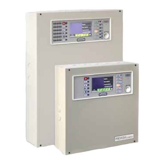
Analog-addressable fire alarm control panel, extinguishant system control panel, alarm transmission and fault warning routing equipment
Hide thumbs
Also See for Previdia Compact:
- User manual (28 pages) ,
- Manual (20 pages) ,
- Manual to networking (20 pages)
Table of Contents
Advertisement
Advertisement
Table of Contents

Related Manuals for INIM Electronics Previdia Compact


Summary of Contents for INIM Electronics Previdia Compact
- Page 1 Configuration manual EN 54-2 EN 54-4 EN 54-21 EN 12094-1 0051 0051-CPR-1498 0051-CPR-1499 ANALOG-ADDRESSABLE FIRE ALARM CONTROL PANEL, MANUAL FOR EXTINGUISHANT SYSTEM CONTROL PANEL, SYSTEM CONFIGURATION, ALARM TRANSMISSION AND FAULT WARNING ROUTING EQUIPMENT COMMISSIONING AND MAINTENANCE...
-
Page 2: Warranty
INIM Electronics s.r.l. (Seller, Our, Us) warrants the original purchaser that this product shall be free from defects in materials and workmanship under normal use for a period of 24 months. As INIM Electronics s.r.l. does not install this product directly, and due to the possibility that it may be used with other equipment not approved by Us; INIM Electronics s.r.l. -
Page 3: Table Of Contents
Configuration manual Table of contents Warranty.......................... 2 Limited warranty......................2 Copyright........................2 Table of contents ......................3 Chapter 1 General information ....................5 Manufacturer's details ........................5 About this manual ..........................5 Description of the configuration and programming procedures ........6 Operator classification - Access Levels ..................6 Chapter 2 Configuration ........................ - Page 4 Fire detection and extinguishant system Table of contents...
-
Page 5: Chapter 1 General Information
INIM Electronics brand devices only. About this manual Manual code: DCMCINE0PREVIDIAC Version: 1.00 This manual describes the procedures for the configuration, commissioning and maintenance of the Previdia Compact fire-detection system. 1.2.1 Graphic conventions Following are the graphic conventions used in this manual. -
Page 6: Description Of The Configuration And Programming Procedures
Following is a flow chart which summarizes the operations to be carried out during the installation and commissioning phases of the Previdia Compact system and indications regarding the manuals to refer to for each operation. Installation and cabling (refer to the Installation Manual) 2. -
Page 7: Chapter 2 Configuration
Configuration manual Chapter 2 Configuration First startup Once the installation and cabling procedures have been completed (refer to the Installation Manual of the Previdia Compact system) the system is ready for first startup. In the case of first startup and after having performed the procedure to set the factory data, it is necessary to enter the unlock code: Please enter the code SHOW... -
Page 8: Access To Programming
- Factory default settings (refer to paragraph 2.5) Accessing the configuration menu The configuration menu allows the programmer to put all the parts of the Previdia Compact System in the configuration (control panel, connections and connected devices) after the initial installation phase. -
Page 9: Access To The Device Modification Menu
Refer to paragraph 5.1 Access to the device modification menu Once the Previdia Compact system has been configured it is necessary to set the parameters, or change the default programming of the devices connected to the control panel (single or in group). -
Page 10: Resetting Factory Default Data
Resetting factory default data The resetting of the factory default data and consequent deletion of the configuration data on the Previdia Compact control panel can be done in two ways: • Selecting the Factory data option from the programming menu (refer to paragraph 2.2). -
Page 11: Chapter 3 System Parameters
Chapter 3 System Parameters The configuration of the Previdia Compact control panel, its interfaces and external connections provides for the settings of a series of parameters reachable from the control panel by accessing control panel programming (paragraph 2.2) and then pressing the Configuration button on the menu shown on the screen. -
Page 12: Configuring The Hornet+ Network
Fire detection and extinguishant system Configuring the Hornet+ network If the installation has control panels connected in a Hornet+ network, it will be necessary to assign the network address to each control panel. To set the network parameters you must enter the programming phase of the control panel (paragraph 2.2) and then tap on the appropriate icon inside the control panel configuration screen. - Page 13 Configuration manual Procedure completed - Found: 73 Enroll: This button performs a loop scan (after command confirmation) which searches for all the connected devices and puts those found into the configuration [A]. 1 Generic 44 Detectors A report of the devices will be shown when the scan ends. 12 IN modules 5 OUT modules 0 IN/OUT modules...
- Page 14 Fire detection and extinguishant system 3.4.2 Loop diagnostics Diagnostics button in the Loop configuration menu accesses the section for the loop diagnosis. The upper left side of the template [A] shows some of the electrical data of the loop. Loopx: loop yyy •...
-
Page 15: Sd Card Functions
Configuration manual SD card functions Tapping on the appropriate icon inside the control panel configuration template accesses some of the functions available on the SD card. A list with the following buttons will appear: • Save Program Data, saves the control panel programming data to the SD card in a .dat file, the name of which coincides with the serial number of the control panel. -
Page 16: Configuring The Communicator
- User level, coincides with “Level 3” (authorized user) User level Type Previdia Compact control panels are supplied at default with Access the first 4 codes already pre-set: level:3 Code number... -
Page 17: Configuring The Extinction Channel
Configuration manual If you are configuring an “SMS” or “PSTN” type channel, the communication protocol will be requested: • SIA-IP • Contact ID • Voice call • SMS The parameters made available in the contact programming section that follows vary according to the selected protocol. Pressing the Actions button [D] on the communicator configuration screen will access the list of communication operations set on the control panel. - Page 18 Selecting “--” for the assigned group disables the related stop-extinction mode. EN12094-1: If the “Stop Extinction ABORT” function is utilized with a Previdia Compact control panel, the “Stop Extinction HOLD” and “Stop Extinction ADD” functions cannot be associated with inputs, and vice versa.
- Page 19 Configuration manual • Disable Disab. Extinguishing Input module 4 This section provides the parameters of disabling the Disab. Man. Exting. Button 3 extinction procedure. There are 3 different modes available for disabling the extinction procedure, each one attributable Disab. Aut. Exting. to a different input: - Disab.
-
Page 20: Setting The Date And Time
Fire detection and extinguishant system The Previdia Compact control panel has pre-configured default output groups with specific extinction functions: Associated Outputs group Activation EN 12094-1 extinction function Extinguishing Group that activates the release of the gas. Release By programming a different... -
Page 21: Firmware Revision
Configuration manual 3.11 Firmware revision FW001PFPMCPU The installer of the Previdia Compact system may access UI:01.00 BUILD:01.01 the firmware revision of each control panel module in order IO:00.00.01 to facilitate any updating or configuration procedure. SW:01.xx.xx The System status button on the home page in stand-by [C]... -
Page 22: Chapter 4 Parameters Of Devices And Their Groupings
Parameters of devices and their groupings The configuration of the devices connected to the loops and the output/input terminals of the Previdia Compact control panel takes into consideration both the setting of parameters, which vary depending on whether the device is an input or output device, as well as their grouping (zones for the points and output groups for the outputs). -
Page 23: Parameters Of Control Panel Terminals
Configuration manual • Input parameters Alarm Mode - Mode, determines the type of event generated by activation of the input. - Group activated, indicates the group that will activate Generic alarm Group activated following input activation. - Prealarm, determines when activation of the input will Always Prealarm start the associated prealarm time. -
Page 24: Zone Parameters
Fire detection and extinguishant system • Input parameters Alarm Mode - Mode, determines the type of event generated by activation of the input. - Group activated, indicates the group that will activate Generic alarm Group activated following input activation. - Prealarm, determines when activation of the input will Always Prealarm start the associated prealarm time. -
Page 25: Replicate Programming Procedure
If activated, you must specify the duration of the pulse Access activation signal (in the box at the bottom) level:3 Replicate programming procedure The Previdia Compact control panel allows you to copy the Zone Status programming of a single element (point, zone, group) and Zone 1 Stand-by replicate it on other elements in its category and group. -
Page 26: Chapter 5 Commissioning
Fire detection and extinguishant system Chapter 5 Commissioning The commissioning phase is a set of tests and verifications which are necessary to ensure the full efficiency and proper functioning of the system as specified in the executive project. This phase is essential and must be performed in a scrupulously in accordance the regulatory requirements of the country where the system is installed and in full respect of the recommendations herein. -
Page 27: Testing To Detectors And Manual Activations
Configuration manual Testing to detectors and manual activations All the installed detectors must be tested during the commissioning phase. It is necessary to check the capacity of each detector to react to a simulated condition of fire, and to check the precision of the signals transmitted to the control panel in response to its activation (description of the point and zone). -
Page 28: Chapter 6 Maintenance
Fire detection and extinguishant system Chapter 6 Maintenance For correct and efficient management of the system it is necessary to carry out periodic maintenance in accordance with the regulatory requirements of the country where the system is installed and in full respect of the recommendations herein. - Page 29 Configuration manual Maintenance...
- Page 30 Fire detection and extinguishant system Maintenance...
- Page 31 User’s manual...
- Page 32 Fire detection and extinguishant system ISO 9001 Quality Management certified by BSI with certificate number FM530352 Centobuchi, via Dei Lavoratori 10 63076 Monteprandone (AP) Italy Tel. +39 0735 705007 _ Fax +39 0735 704912 info@inim.biz _ www.inim.biz DCMCINE0PREVIDIAC-100-20180910...
Need help?
Do you have a question about the Previdia Compact and is the answer not in the manual?
Questions and answers