Table of Contents
Advertisement
Advertisement
Table of Contents

Related Manuals for INIM Electronics SmartLine Series


Summary of Contents for INIM Electronics SmartLine Series
- Page 1 0051 EN 54-2 0051-CPR-1412 EN 54-4 0051-CPR-1413 EN 54-21 EN 12094-1 0051-CPR-1414 SmartLine Conventional fire detection control panel Extinguishant system control panel Alarm transmission and fault warning routing equipment with integrated power supply equipment Installation and programming manual...
-
Page 2: Copyright
Conventional fire detection control panel Copyright The information contained in this document is the sole property of INIM Electronics s.r.l.. No part may be copied without written authorization from IINIM Electronics s.r.l.. All rights reserved. European directive compliance This Control panel has been designed and developed to the highest standards of quality and performance implemented by INIM Electronics s.r.l.. -
Page 3: Table Of Contents
Installation and programming manual Table of contents Copyright ................2 European directive compliance ..........2 Table of contents..............3 Chapter 1 Overview................5 Application and use 5 Other parts of the system 7 The SmartLine fire alarm panel models 7 Chapter 2 General information .............. - Page 4 Conventional fire detection control panel 6.15 Connecting the mains power source 41 6.16 Connecting the batteries 42 6.17 Thermal probe 43 Chapter 7 Powering up and configuring the system ........ 44 Testing wiring integrity 44 Connecting the RS232 PC serial link 44 Powering up the system 45 Chapter 8 Introduction to Programming from the panel ......
-
Page 5: Overview
The control panels described in this manual have been designed and manufactured to the highest standards of quality, reliability and performance adopted by INIM Electronics. The components selected for these products will operate properly within their specifications when the environmental conditions outside the product enclosure comply with Class 3k5 (EN60721-3-3.). - Page 6 Conventional fire detection control panel [A] The zones Each zone is provided with a pair of terminals (lines) for the connection of the fire-detection devices deployed in the protected area. Each line (zone) accepts up to 30 devices (conventional detectors or call points).
-
Page 7: Other Parts Of The System
Installation and programming manual [F] SmartLink Advanced telephone dialler INIM's SmartLink/G and SmartLink/GP telephone dialers monitor the analogue landline and, in the event of landline problems (line cutting, etc.) divert incoming and outgoing calls to the GSM network. The SmartLink/P model operates solely over the PSTN line (landline). [G] SmartLAN/485 Ethernet connection board (accessory item) Allows the control panel to connect to an Ethernet network for remote connection. -
Page 8: General Information
Electronics, and refers to the devices specified in paragraph 2.12. Disclaimer INIM Electronics s.r.l. shall not be responsible for damage arising from improper application or use. This control panel should be handled by qualified personnel only. Installation must be carried out strictly in accordance with the instructions described in this manual, and in compliance with the local fire code in force. -
Page 9: Recommendations
Installation and programming manual Recommendations INIM Electronics recommends that the entire system be checked completely at regular intervals (refer to paragraph 2.7 - System test). System test This system has been designed to provide the highest standards of reliability and performance. Malfunction of any of the system devices may cause the system to be incapable of reaching the intended levels of performance. -
Page 10: Menu Paths
For most part this manual describes programming from the control panel. 2.12 CE Mark 0051 0051 0051 INIM ELECTRONICS S.R.L. INIM ELECTRONICS S.R.L. INIM ELECTRONICS S.R.L. via Dei Lavoratori 10 - fraz. Centobuchi via Dei Lavoratori 10 - fraz. Centobuchi via Dei Lavoratori 10 - fraz. Centobuchi... -
Page 11: Warranty
Installation and programming manual 2.13 Warranty INIM Electronics s.r.l. warrants that for a period of 24 months from the date of commissioning, the product shall be free of defects in materials and workmanship. The warranty applies only to defects in parts and workmanship relating to normal use. -
Page 12: Replacement And Disposal Of Used Devices
Conventional fire detection control panel 2.15 Replacement and disposal of used devices Replacement When replacing obsolete devices, disconnect the devices concerned then complete the connections of the new devices in compliance with the instructions printed on the respective leaflets. In order to avoid short-circuits, take all the necessary precautions when removing used batteries. Disposal Do not burn used electronic devices, or allow them to pollute the environment (countryside, rivers, etc.). -
Page 13: Device Management
Installation and programming manual Chapter 3 Device management Product handling and storage This device is safely packed inside a cardboard box, however, care must be taken to avoid accidental damage during handling. Cartons/boxes should be placed in such a way as to avoid knocks and falls, and special care must be taken to protect the devices from extreme heat and/or cold. - Page 14 Conventional fire detection control panel Figure 3 - Thermal probe and accessory devices Device management...
-
Page 15: Technical Description
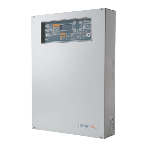
Installation and programming manual Chapter 4 Technical description Control panel Figure 4 - External and internal parts of the SmartLine020 Frontplate with display, keys and signalling LEDs Slot for level 2 access key Frontplate Securing screws for the front cover Cable entries (located on all sides of the enclosure) Data label... -
Page 16: Internal Devices
Conventional fire detection control panel Internal devices Figure 6 - SmartLine motherboard Main components: ZONE +/- Zone detection-line terminals ZONE I/O Zone I/O terminals RS485 RS485 BUS terminals for repeater and power station connections, max. 0.9 A FAULT Fault output, dry contact DIALER Output terminal for dialler connection, supervised ALARM NAC... - Page 17 Installation and programming manual SmartLine020 SmartLine020 Power Supply Power Supply Figure 7 - Switching power supply The switching power supply is attached to the backplate of the metal enclosure. The power supply type depends on the control panel model. SmartLine020 SmartLine036 Mains input terminal board AC Input...
-
Page 18: Technical Specifications
Conventional fire detection control panel Technical specifications Specification SmartLine020 SmartLine036 AC power 230V (-15% / +10%) 50/60Hz Maximum current draw 230V 0.5 A 1.1 A Nominal output voltage 27.6 V Maximum output current 2.1 A 5.2 A 1.5 A max. a 1.5 A max. -
Page 19: User Interface
Installation and programming manual Chapter 5 User interface Figure 8 - Frontplate SmartLine panel frontplate 5.1.1 Commands Command Access level 1 Access level 2 Note Navigation keys To be used to navigate through the menus on the display. Their effect varies in accordance with the context. - Page 20 Conventional fire detection control panel Command Access level 1 Access level 2 Note EVACUATE If this button is pressed If this button is pressed when during active pre-alarm pre-alarm conditions are not conditions, the system active, the system will generate will override the a panel alarm.
- Page 21 Installation and programming manual If On solid: If Blinking: Note ALARM Signals an alarm Examples: a smoke detector has sensed a (red) condition, that is, quantity of smoke that exceeds its alarm activation of a zone point threshold; a heat detector has sensed rise (detector, call point, in temperature that exceeds its alarm etc.) that is programmed...
- Page 22 Conventional fire detection control panel If On solid: If Blinking: Note TEST Indicates test status on A zone in test status cannot generate (yellow) one or more zones. alarms or signalling of any kind. However, the respective LED will turn on for several seconds and then reset and turn off automatically.
- Page 23 Installation and programming manual If On solid: If Blinking: Note [A1] DISABLE Indicates disablement of MANUAL manual extinguish commands, via the appropriate key (paragraph 5.1 - [I]). [B1] EXTINGUISH Indicates that fire extinction is running. [C1] PRE- Indicates activation of Indicates that only one EXTINGUISH the pre-extinguish...
-
Page 24: Repeater (Add-On Panel)
Conventional fire detection control panel Repeater (add-on panel) Up to four repeater panels can be connected to the RS485 bus. Connected repeater panels replicate all the information provided by the control panel and allow access to all level 1 and 2 functions (view active events, reset, silence, etc. - Page 25 Installation and programming manual 5.2.2 LED If On solid: ON blinking: SILENCED As per paragraph 5.1 RESET DISABLED As per paragraph 5.1 INVESTIGATE Indicates that investigation time has been requested. ALARM As per paragraph 5.1 PRE-ALARM As per paragraph 5.1 FAULT As per paragraph 5.1 CPU FAULT...
- Page 26 Conventional fire detection control panel 5.2.3 Repeater board If you open the repeater enclosure, the rear side of the electronic board (which is attached to the frontplate) will be on view. Following is a description of the parts which will be used during the installation phase: Figure 10 - The rear side of the repeater board [A] DIP switches...
-
Page 27: Installation Instructions
Installation and programming manual Chapter 6 Installation instructions Mounting the SmartLine/8Z expansion board (accessory item) The SmartLine/8Z zone expansion board can be used with the SmartLine020-4 and SmartLine036-4 models. The SmartLine020-4 control panel can manage 2 SmartLine/8Z boards (8 zones each board) bringing the total number of zones to 20, while the SmartLine036-4 control panel can manage up to 36 SmartLine/8Z boards, bringing the total number of zones to 36. -
Page 28: Mounting The Smartlan/485 Ethernet Board (Accessory Item)
Conventional fire detection control panel Figure 12 - Mounting the expansion board - 2 1. Remove the four screws and detach the frontplate of the metal enclosure. 2. Remove the four screws and detach the plastic support. 3. Attach the expansion board to the anchor plate, use the metal spacers if you are installing two boards (Figure 11 - [A]). -
Page 29: Mounting The Smartletloose/One Extinguishant Board (Accessory Item)
Installation and programming manual As a result of this feature, the fire-detection panel can be supervised through INIM's custom software (SmartLook), or integrated into any supervisory software. For further details and for the installation procedure, refer to the manual provided with the board. Mounting the SmartLetLoose/ONE extinguishant board (accessory item) The extinguishant board comes in a separate cardboard box. -
Page 30: Connecting The Lines
Conventional fire detection control panel 6.4.2 SmartLetUSee/LCD-Lite repeater (accessory item) 1. Remove the four frontplate screws and lift off the frontplate. 2. Pass the cables through the cable entry on the back of the repeater. 3. Prepare the wall for the four 8mm anchor screws (stop screws) which must be positioned in accordance with the holes on the backplate of the metal enclosure of the repeater. - Page 31 Installation and programming manual WHITE GOLD ORANGE Figure 16 - Wiring for detection with missing detectors If detectors are wired as per the diagram and the “Det.Missing” option is enabled, the control panel will generate a fault signal when a detector is removed from its base and at the same time will be able to receive alarm signals from other detectors connected downstream.
- Page 32 Conventional fire detection control panel CONTACT WHITE ORANGE GOLD GRAY BROWN GOLD BLUE Figure 18 - Connecting generic contacts to the detection line The wiring diagram above illustrates the connection of a generic device (call point, switch, generic device output) to the detection line. If the line is wired in this way, it will signal a fault when a short-circuit or cable interruption occurs, and will generate the pre-set line signals (alarm, sprinkler, change class, etc.) when the contact closes.
- Page 33 Installation and programming manual CONTACT VIOLET ORANGE WHITE YELLOW GOLD ORANGE GOLD GREEN ORANGE BROWN GOLD Figure 20 - Wiring the I/O line as an input The diagram above illustrates a line wired as an input. The EOL resistor will allow the control panel to supervise the wiring, and the resistor connected in series to the activation contact will allow it to discriminate between an activation signal and short-circuit.
-
Page 34: Connecting An Alarm Dialler
Conventional fire detection control panel 2. Fire alarm wires must be separate from other power wiring circuits. 3. All cabling, connections and junctions should be completed using the local country Fire Code compliant method. 6.5.4 Fire code guidelines Danger: All circuits should be wired using the local country Fire Code compliant method. Connecting an alarm dialler The control panel dialler must have an activation terminal that will generate calls when it connects to GND (activation -A). -
Page 35: Connecting The Rs485 Bus
Installation and programming manual GREEN ORANGE BROWN GOLD POWER-SUPPLY DIALER BLACK BROWN GOLD Figure 24 - Connecting the dialler 6.7.1 Wiring 1. Connect the dialler to terminals - and I/0 of zone 4 of the control panel. 2. Add a 1 k1W resistor to the dialler between the activation terminal and the + terminal. This resistor will monitor the integrity of the connection between the panel and the dialler and will signal promptly any short-circuits or interruptions. - Page 36 Conventional fire detection control panel 6.8.1 Wiring 1. Use a 4 pole shielded-twisted cable. 2. The cable length between the panel and repeater must not exceed 1000 m. 3. Connect the shield to earth (terminal 6 can be used for this connection). 6.8.2 Setting the addresses of devices connected to the RS485 BUS 1.
-
Page 37: Connecting The Fault Signalling Outputs
Installation and programming manual Connecting the fault signalling outputs The control panel provides a Fault signal output (normally open, non-supervised contact). FAULT signalling sign Figure 28 - Connecting the fault signal output During standby status, the 2 terminals will be open. If the control panel detects any type of fault, the two terminals will close together. -
Page 38: Connecting Nac Outputs To The Smart/8Z Expansion Board
Conventional fire detection control panel 6.10.1 Wiring 1. Use NON-shielded cable. The wire section should be compatible with the wire length and load connected to the output. 2. Connect the EOL resistor (included) in parallel to the last device on the line (47 K). 3. -
Page 39: Connecting Relay Output
Installation and programming manual 6.13 Connecting RELAY output Device to activate Figure 31 - Connecting RELAY output The RELAY output provides a dry contact that can switch 1A 30V loads. At default the relay is configured to activate in the event of an alarm but can be configured to activate in the event of various conditions. Note: In order to validate the IMQ-SECURITY SYSTEMS certification, this output should not be used as a type C, E or J output (EN 54-1), and must not be used to command Fire-alarm or Fault transmission devices. - Page 40 Conventional fire detection control panel VIOLET ORANGE YELLOW GOLD SmartLine control panel STOP- VIOLET ORANGE EXTINCTION YELLOW GOLD signalling LED Figure 32 - Extinguishant module 6.14.1 Inputs Device to be Terminal Input Type Note Wiring Diagram connected MAN-EXT Extinction system Supervised.
-
Page 41: Connecting The Mains Power Source
Installation and programming manual 6.14.2 Outputs Device/s to Terminal Output Type Note Wiring Diagram connect VALVE Electrovalve for Supervised Figure 32 - gas release. Extinguishant module/B PRE-EXT Audible and Visual Supervised The signalling devices activate as soon as Figure 32 - signalling devices the detectors sense fire conditions that Extinguishant... -
Page 42: Connecting The Batteries
Conventional fire detection control panel SmartLine020 SmartLine036 control panel control panel Figure 33 - Earthing system 2. Crimp the earth line wire to the eyelet terminal [B] (included in the package). 3. Attach the wire with the eyelet to the control panel using the ground connection screw [C]. 4. -
Page 43: Thermal Probe
Installation and programming manual SmartLine020 SmartLine036 Power Supply Power Supply Figure 34 - Connecting the batteries 1. Connect the connection wire [A] to the two batteries. 2. Connect the wire [B] to the batteries. Attention: Be sure that cable polarity is correct. 3. -
Page 44: Powering Up And Configuring The System
Conventional fire detection control panel Chapter 7 Powering up and configuring the system Testing wiring integrity Before powering-up the system, check the wiring integrity and the isolation between the wires and earth. 1. Remove the jumper (paragraph 4.2 - [L]) in order to bypass earth fault check. 2. -
Page 45: Powering Up The System
Installation and programming manual Note: The RS232 link can be ordered separately. If your PC does not have a RS232 port but has a USB, use an RS232-USB adapter. Powering up the system 1. Connect the connection wire between the two batteries and the batteries to the proper connector of the power-supply module (refer to paragraph 6.16 - Connecting the batteries). -
Page 46: Introduction To Programming From The Panel
Conventional fire detection control panel Chapter 8 Introduction to Programming from the panel The control panel and its zones and outputs can be programmed and configured via the control panel or by means of the SmartLeague software program. For a brief description of the software application and the programming process, refer to Chapter 14 - SmartLeague software or, for a more complete description, refer to the User's Manual of the SmartLeague software. -
Page 47: Programming From Panel
Installation and programming manual Chapter 9 Programming from panel This section describes how to program the control panel. Configuring the control panel From panel: <key>, Programming, Configuration The first step is to configure the control panel. Press Ok after you select “Acquire int. bus”, the display will show the current configuration of the control panel (i.e. - Page 48 Conventional fire detection control panel Detection line Press Ok when the cursor is positioned on this line, to access the programming page relating to the detection line of the selected zone. I/O line Press Ok when the cursor is positioned on this line, to access the programming page relating to the I/O line of the selected zone.
- Page 49 Installation and programming manual The line will operate as a resettable alarm line (it will remain active for the duration of the alarm condition). Activation of the line will generate a fire alarm and the display will indicate activation of the “Sprinkler” system. The line will also generate the “Sprinkler” signal that can SPRINKLER be used for the activation of specific outputs which provide separate signals.
- Page 50 Conventional fire detection control panel 9.2.3 I/O detection line parameters <aaaaaaaaaaaaa> Zone Description (e.g.downstairs kitchen). The field cannot be edited at this point. If you wish to change the string, you must step back to the previous menu. Line type Using the Ok key, scroll the various programming options for the I/O line: In this mode, the line will operate as an Open-Collector output that will activate in response to any of the selected signals ("Alarm", "Pre-alarm", "Gas alarm", "Gas pre-alarm", "Sprinkler",...
- Page 51 Installation and programming manual Inverted As above. Duration As above. -- min -- sec In this mode, the line will operate as an Open-Collector output that will activate when the average reading of the values relating to the 4-20 mA gas detector, connected to the I/O lines of the OUTPUT GAS OUTPUT selected zones, exceeds the set level.
- Page 52 Conventional fire detection control panel The line will operate as a resettable alarm line (it will remain active for the duration of the alarm condition). Activation of the line will generate a fire alarm and the display will indicate activation of the “Sprinkler”...
-
Page 53: Setting The Timers
Installation and programming manual In this mode, the output will activate when any of the control panel components is bypassed (if OUTPUT DISABLE- "Panel" option is selected), or when one or more zones (all the zones set as “YES”) are MENTS bypassed. -
Page 54: Setting Holidays
Conventional fire detection control panel Start/End time 2 Hour and minutes of the Start and End of the interval 2. Day, Month, Year Operational date of the timer. To indicate any day, month or year, leave “--” (for example, every 3rd of the: day=3, month = “--”, year = “--”). Sunday, etc. -
Page 55: Setting Up Equations
Installation and programming manual Night silence time The duration (0 to 10 minutes) of Silence status when the system is operating in Night mode (starting from the moment the SILENCE key is pressed). Time lock reset The period (0 to 30 minutes), after extinction activation, when reset operations are not allowed. -
Page 56: Detection Line Threshold-Adjustment
Conventional fire detection control panel Chapter 10 Detection line threshold-adjustment By means of the guided threshold settings procedure, it is possible to configure the intervention thresholds of the detection lines and I/O lines configured as "INPUT GAS 4-20mA". From panel: <key>, Programming, Progr. Zone, select a zone, Detection line or I/O line, Modify levels, Use wizard, Ok The control panel will ask you to perform a series of operations on the line you are working on (open the line then press Ok, Balance the line then press Ok, etc.). -
Page 57: Programming The Extinguishant Board
Installation and programming manual Chapter 11 Programming the extinguishant board The extinguishant board manages a gas extinguishant system activated by automatic or manual commands: • automatic commands triggered by the fire-control panel when the programmed zones go into alarm status. •... -
Page 58: Configuring The Extinguishant Module
Conventional fire detection control panel To ensure proper programming of the gas extinguishant system you must: 1. Configure the extinguishant module 2. Program the operating principles 3. Configure the Detection lines and I/O utilized by the extinguishant module 11.1 Configuring the extinguishant module From panel: <key>, Programming, Configuration, Acquire int.bus, Ok, Ok This function allows the control panel to detect the presence of the expansion boards and the extinguishant module. -
Page 59: Programming Extinguish Inputs/Outputs
Installation and programming manual Time pre- The duration of the manual pre-extinction phase, activated by a MAN-EXT input or Detection line extinction set up as a manual extinction input. manual Confirm Delay between activation of the electrovalve output and the pressure switch activation analysis extinguish time (if programmed as "Confirm extinguish"). -
Page 60: Configuring The Devices Connected To The Rs485 Bus
Conventional fire detection control panel Chapter 12 Configuring the devices connected to the RS485 BUS From panel: <key>, Programming, Configuration, Acquire ext.bus, OK, Ok The SmartLetUSee/LCD-Lite repeaters are clone panels. They are equipped with displays and LEDs and replicate all the information provided by the control panel. The panel supports up to 4 repeaters which, under normal circumstances, should be located at entrances/exits, in such way as to allow building occupants or fire officers to view alarm details without going too far inside the building. -
Page 61: Closing The Programming Session
Installation and programming manual Chapter 13 Closing the programming session Once you have completed the programming, remove the panel/PC programming jumper. The panel will be ready to go into service, and the display will be as follows. Double check the functionality of all the input devices. C on tro l pan el In s erv ic e 01/ 01 /18... -
Page 62: Smartleague Software
Overview The SmartLine system can be programmed from the panel or from a PC. You can access all the programming process via the SmartLeague programming and management software for INIM Electronics security products. The SmartLeague software program allows you to access all the system parameters which can be accessed via the control panel. -
Page 63: Maintenance
Installation and programming manual Chapter 15 Maintenance The following operations must be carried out regularly. 1. Using a damp lint-free cloth, remove any dust that may have gathered on the control panel (do not use any kind of cleaning product or solvent!). 2. -
Page 64: Bypassing A Zone
Conventional fire detection control panel 15.3.2 Night There are no people in the building, therefore, there is only one person in charge of building safety (e.g.: night watchman, guard). Silence The Silence command holds off signalling. The Silence phase will run for the pre-set time. If no-one intervenes during this phase, the system will undo the silence command and the alarm will continue. -
Page 65: Set The Date For The Next Maintenance Session
Installation and programming manual 1. Press Ok to activate/deactivate the output. Zon e <Zo ne 0 4> 2. Press or to go to the adjacent output. 15.8Set the date for the next maintenance session From panel with the jumper inserted:<key>, Maintenance, Maintenance date, Ok If you have set the date of the next maintenance session, the system Mai nt . -
Page 66: Diagnostics And Fault Solutions
Conventional fire detection control panel Chapter 16 Diagnostics and fault solutions Danger: Only authorized operators (Level 2 or 3) may search for, and correct faults. 16.1 Fault “Open” The panel is unable to find the EOL resistor on the supervised input/output terminals. The following line will specify the terminals concerned (NAC, detection line, I/O line, etc.). -
Page 67: Other Faults
Installation and programming manual The batteries are running low. This signal should be present only during primary power source failure (Mains 230V ). Mains power must be restored in order to charge the batteries. 16.5 Other faults The panel shows the message: Meaning Trouble on the dialler communication line (dialler output). -
Page 68: Iris Devices
The operating parameters of detectors may be modified to suit their specific environments and, when used in conjunction with the EITK-DRV supplied by INIM Electronics. This device allows you to connect directly to the detector line for a complete diagnosis of each detector and thus test its operating capacity, verify its real-time values, view the contamination level in the optical smoke chamber and change its sensitivity and operating mode. - Page 69 Installation and programming manual The distinct serial number of each detector is shown on the device information label. Figure 37 - The reverse side of Iris detectors The serial number is shown on the information label [A] and on two smaller removable labels [B]. When installing the devices, it is strongly advises to remove the small labels and place one on the system layout and the other on the mounting base.
- Page 70 Conventional fire detection control panel Iris devices...
-
Page 71: Notes
Installation and programming manual Notes Notes... - Page 72 ISO 9001 Quality Management certified by BSI with certificate number FM530352 via Dei Lavoratori 10 - fraz. Centobuchi 63076 Monteprandone (AP) ITALY Tel. +39 0735 705007 _ Fax +39 0735 704912 info@inim.biz _ www.inim.biz DCMIINE0SLINE-360-20180719...
Need help?
Do you have a question about the SmartLine Series and is the answer not in the manual?
Questions and answers