Table of Contents
Advertisement
Quick Links
Register your system now for driver
updates and access to our Training Site!
TRAINING.EPILOGLASER.COM/REGISTER
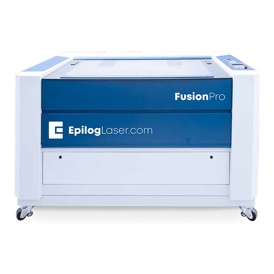
FusionPro 32/48
Laser System Manual | Model 16000
Original Instructions
Technical Support: +1 (303) 215-9171
Knowledge Base: support.epiloglaser.com
System Registration:
training.epiloglaser.com/register
Driver/Firmware: epiloglaser.com/fusionpro-drivers
UPDATED MAY 2019 |
EPILOGLASER.COM/MANUALS
Advertisement
Table of Contents

Subscribe to Our Youtube Channel
Related Manuals for Epilog Laser FusionPro 32


Summary of Contents for Epilog Laser FusionPro 32
- Page 1 FusionPro 32/48 Laser System Manual | Model 16000 Original Instructions Technical Support: +1 (303) 215-9171 Register your system now for driver Knowledge Base: support.epiloglaser.com updates and access to our Training Site! System Registration: training.epiloglaser.com/register TRAINING.EPILOGLASER.COM/REGISTER Driver/Firmware: epiloglaser.com/fusionpro-drivers UPDATED MAY 2019 |...
-
Page 3: Table Of Contents
TABLE OF CONTENTS FIRE WARNING INTRODUCTION How to Use This Owner’s Manual .............................. 2 Icons Used in this Manual ................................2 SECTION 1: SAFETY Laser Safety ......................................3 Electrical Safety ..................................... 3 Safety Features and Regulatory Compliance ......................... 4 Dos and Don’ts ..................................... 10 SECTION 2: GETTING STARTED 1. - Page 4 Federal Communications Commission (FCC) Notice ....................124 SECTION 12: TECHNICAL SUPPORT Contacting Technical Support ..............................125 Frequently Asked Questions ..............................126 Join Epilog Laser’s Online Community ..........................128 SECTION 13: MATERIAL SUPPLIERS Industry Material Supplier List ..............................129 APPENDIX A: WARRANTY STATEMENT Warranty Statement for the Fusion Pro Laser ......................
-
Page 5: Fire Warning
FIRE WARNING Fire Warning Your laser system uses a high intensity beam of light that can generate extremely high temperatures when it comes into contact with the material being engraved, marked or cut. Some materials are extremely flammable and can easily ignite and burst into open flame setting the machine afire. -
Page 6: Introduction
You will be ready to use the Epilog Laser system as soon as you read the first few sections. -
Page 7: Section 1: Safety
SECTION 1: SAFETY Laser Safety The standard reference for laser safety is the American Standard for the Safe Use of Lasers, Z136.1-2000, developed by the American National Standards Institute (ANSI). This reference is the basis for many of the federal regulations for laser and laser system manufacturers, and for the Occupational Safety and Health Administration (OSHA) laser safety guidelines. -
Page 8: Safety Features And Regulatory Compliance
SECTION 1: SAFETY Safety Features and Regulatory Compliance Epilog has incorporated specific safety features into the Model 16000 Laser System in order to meet the requirements of 21 CFR 1040 and the International Standard IEC 60825-1. These safety features include: •... - Page 9 SECTION 1: SAFETY 3. Descriptive Label: This label identifies the classification of the Model 16000 in accordance with 21 CFR 1040.10 and IEC 60825-1. It is located on the right side of the machine’s cabinet, below the Warning Logotype. 4. Non-interlocked Protective Housing Safety Labels: These labels are located on, or adjacent to, removable access covers on the machine’s cabinet as shown in the diagrams to follow.
- Page 10 SECTION 1: SAFETY The following diagrams show the location of each specific label. Fusion Pro 32: - 6 -...
- Page 11 SECTION 1: SAFETY Fusion Pro 48: - 7 -...
- Page 12 SECTION 1: SAFETY - 8 -...
- Page 13 FCC: Supplier’s Declaration of Conformity 47 CFR Paragraph 2.1077 Compliance Information Laser Materials Processing System Model 16000 Epilog Laser Corporation 16371 Table Mountain Parkway Golden, CO 80403 Telephone: (303) 277-1188 This device complies with Part 15 of the FCC Rules. Operation is...
-
Page 14: Dos And Don'ts
SECTION 1: SAFETY Dos and Don’ts Don’ts Do Not Run the Laser Unvented: Never operate the machine without a properly operating vent to the outside or to a filtration unit! Most material will only produce an irritating smoke when engraved. Some materials, including but not limited to paint, varnish, composition board and plastics, produce compounds that can be harmful if concentrated. -
Page 15: Section 2: Getting Started
SECTION 2: GETTING STARTED Setting up your Epilog Laser System is easy to do! If you’ve ever installed a paper printer, this is only slightly more difficult. The following information will help you understand the entire system and how it works. -
Page 16: Unpacking The Laser System
SECTION 2: GETTING STARTED 1. Unpacking the Laser 3. Remove the screws securing the front panel. System Unpack the laser system from the crate provided by Epilog. Please be sure to hold on to all packing materials and crating in case you need to move the system in the future. - Page 17 SECTION 2: GETTING STARTED 5. Remove the outer screws holding up the two Using the top panel you removed at the braces. beginning, align its corners with the ledge on the bottom of the box, making a ramp. Secure the ramp with a screw. 8.
-
Page 18: Choose Where To Locate The System
Cooling Requirements and Operating Temperatures All Epilog Laser systems use air-cooled laser tubes. Laser technology is such that the laser tubes generate a lot of excess heat and the tubes must be cooled for proper operation. There are cooling fans located on both sides of the laser. -
Page 19: Connecting The Exhaust
Please note that this is also a recommendation and not a requirement, because factors such as length and type of tubing from the Epilog laser to the exhaust fan and from the exhaust fan to the outside of the building can produce significant losses on the true amount of air that is drawn from the Epilog laser. - Page 20 SECTION 2: GETTING STARTED Epilog Exhaust/Filter Connections There are two 4” (102 mm) ports attached to the back of the Fusion Pro 32 laser system, and three 4” (102 mm) ports attached to the back of the Fusion Pro 48 laser system. Attach your ducting to the machine as shown in the diagram.
-
Page 21: Connecting Electrical Power
SECTION 2: GETTING STARTED 4. Connecting Electrical Power Epilog supplies the appropriate power cord for the system you ordered. The power cord is found in the accessory package with your machine. The power cord for the laser plugs into the power receptacle located on the left side of the machine in the rear corner. -
Page 22: Set The Fusion Pro's Ip Address
SECTION 2: GETTING STARTED Ethernet Connection The Ethernet Port is a standard 10BaseT connection. Your Epilog Laser has all of the versatility of a network capable peripheral. As such, there are many different ways that the laser can be connected to a computer or a network. -
Page 23: Sign Up For Driver Updates And Register Your System
SECTION 2: GETTING STARTED USB Cable Setup Once your machine is booted up, select the Settings button in the upper right corner of the touchpad. 2. Select USB in the settings list. 3. Under USB you will see “IP Address” and “Netmask”, press “IP Address” and then press the numbers that appear next to them. -
Page 25: Section 3: Software Installation
It’s a great addition to the Epilog Laser product features, and we look forward to seeing how our customers use this software! •... - Page 26 SECTION 3: SOFTWARE INSTALLATION 3. Select “Remove all components” and then click “Next”. 4. Click “Uninstall”. 5. Click Finish to complete the uninstallation of the previous Job Manager. - 22 -...
-
Page 27: Windows 7: Ethernet Installation
SECTION 3: SOFTWARE INSTALLATION Windows 7: Ethernet Installation Set Up TCP/IP Address in the Computer Go to your Network and Sharing Center in your computer’s Control Panel. Click Change Adapter Settings. 2. Right click Local Area Connection, then click Properties. - 23 -... - Page 28 SECTION 3: SOFTWARE INSTALLATION 3. Select Internet Protocol Version 4 (TCP/IP). Make sure you do not select Version 6. 4. Select Use the following IP Address. Type in the following IP Address: 192.168.3.3. This number is not an error; the last digit of the IP address in this window must be different than the IP address you set in the laser.
-
Page 29: How To Install The Epilog Job Manager
SECTION 3: SOFTWARE INSTALLATION How to Install the Epilog Job Manager Go to epiloglaser.com/drivers and select the Epilog Fusion Pro. Then click on the Epilog Software Suite to download the installation file. 2. The installation file will download as a .zip folder that will need to be extracted. Right click the folder and click “Extract All”. - Page 30 SECTION 3: SOFTWARE INSTALLATION 3. A welcome screen appears, click Next. 4. Select a directory location for the installation file and click Next. - 26 -...
- Page 31 SECTION 3: SOFTWARE INSTALLATION 5. Read and accept the license agreements and click Next. 6. Click Next to use the default start menu, or choose a start menu name of your choice. - 27 -...
- Page 32 SECTION 3: SOFTWARE INSTALLATION Click Install to begin the installation. 8. The Epilog Software Suite will begin installing, during the installation a dialog box will pop up to also install the AGPL Ghostscript Package, click Next. - 28 -...
- Page 33 SECTION 3: SOFTWARE INSTALLATION Read and accept the AGPL Ghostscript License Agreement, then click Next. 10. Click Finish to complete the AGPL Ghostscript installation and resume the Epilog Software Suite installation. - 29 -...
- Page 34 SECTION 3: SOFTWARE INSTALLATION 11. Select whether or not you want to run the program now. Click Finish to complete the installation. 12. An icon for the Job Manager will be automatically added to your Desktop. You are now ready to use the Job Manager.
-
Page 35: Troubleshooting The Job Manager
SECTION 3: SOFTWARE INSTALLATION Troubleshooting the Job Manager If you were unable to install the Job Manager, it’s possible that your Anti-Virus software is blocking installation. To disable Symantec Anti-Virus software, choose Options. Other anti-virus packages should have something similar to Symantec. Disable all Virus and Spyware Protection Features. -
Page 36: Important Job Manager Notes
SECTION 3: SOFTWARE INSTALLATION Important Job Manager Notes • Warning: Before activating your laser, install the newest version of the driver to properly associate the correct machine with the Job Manager. • We suggest a minimum of 1 GB of free RAM space when managing very large raster and vector jobs. - 32 -... -
Page 37: Section 4: The Job Manager
SECTION 4: THE JOB MANAGER Using the Epilog Job Manager The first time you open the Job Manager you’ll see a tab for each of the machine models. Begin by selecting the correct model, naming your machine, setting the IP Address, and selecting the correct laser wattage, then click Save. -
Page 38: Printing To The Epilog Job Manager
SECTION 4: THE JOB MANAGER Printing to the Epilog Job Manager Create a file in your graphic software and select Print. When the print dialog opens up, make sure you select Epilog Engraver as your printer and set the Page to Match Orientation and Size. Once your desired settings are selected, click Print again. - Page 39 SECTION 4: THE JOB MANAGER Create and Delete Job Folders Click the Add Job Folders icon to add folders. You can add as many folders as you’d like. Type in the folder name and click the check mark to create your new folder. - 35 -...
- Page 40 SECTION 4: THE JOB MANAGER Move an Uncategorized File to a Folder When you highlight a folder you will see From Uncategorized on the right side of the folder. Click From Uncategorized to move a job from the Uncategorized folder to this subfolder. Select the job you want to move and click OK.
- Page 41 SECTION 4: THE JOB MANAGER Move a Job Between Folders You can also move any job to another folder or subfolder by clicking and dragging it up or down between folders. An arrow will indicate where you are placing the job. Once you see the arrow selecting the correct folder, let go of the job file to place it in that folder.
-
Page 42: Previewing Your Job
SECTION 4: THE JOB MANAGER Previewing Your Job To view a preview of the job, double click on one in the Jobs Tab. A Preview Tab will open and you can preview the combined raster vector job, just the raster components, or just the vector components. We have selected vector to show only the vector components of this job. -
Page 43: Finding Job History
SECTION 4: THE JOB MANAGER Notice that the jobs are displayed differently if you change the search category to Alphabetical. Your jobs are now displayed in alphabetical order. Once the search is finished, most users revert back to the default selection of Standard. Finding Job History You can find the Job Manager Print History under the Laser System tab to see a full print history of a machine, including settings you used in each print. -
Page 44: Vector Sorting
SECTION 4: THE JOB MANAGER Vector Sorting You can determine the cutting order of vector lines directly from the Epilog Job Manager. You can choose from three different vector sorting options: None: Vector line cutting order is determined by the order they were created. 2. -
Page 45: Material Settings Tab
SECTION 4: THE JOB MANAGER Material Settings Tab The Material Settings Tab allows you to save and import settings for individual processes. If you frequently use the same settings for engraving or cutting, this feature allows you to import those settings into a single process quickly. - Page 46 SECTION 4: THE JOB MANAGER 3. Now go to the Epilog Dashboard and set up the file to your preferred settings. Click on the process that has settings you want to save. In this example we have clicked on CMYK Blue. The Process box should open, then click the “Export Settings to Material”...
- Page 47 SECTION 4: THE JOB MANAGER Importing Material Settings To import previously saved settings to a new job, click on the process you want to apply the settings to. Then click the “Import Material Settings” button. 2. A box will appear asking you to select the settings you want to load into this process. Select your settings and click “Import”.
-
Page 48: Job Settings Tab
SECTION 4: THE JOB MANAGER Job Settings Tab The Job Settings Tab allows you to store all the information that is in a job, except for the artwork, as a file you may import into future jobs. If you have a project you run frequently that requires the same settings every time, this feature allows you to import those settings quickly. - Page 49 SECTION 4: THE JOB MANAGER Importing Job Settings To import previously saved settings to a new job, click the Import Job Settings button at the bottom of the screen. 2. A box will appear asking you to select the settings you want to load into this job. Select your settings and click “Import”.
-
Page 50: Changing Program Settings
SECTION 4: THE JOB MANAGER Changing Program Settings You can access the Program Settings by clicking on the gear at the top right of the page. On this screen you can set several different system settings, including: Display Tab: • Language: Choose from several languages. -
Page 51: Section 5: The Laser Dashboard
SECTION 5: THE LASER DASHBOARD The Epilog Dashboard is your portal between your graphic file and the laser. Install your Dashboard at epiloglaser.com/drivers. There are four main areas we’ll cover to get you started: Sending Your First Project 2. Presetting Your Cut Lines 3. -
Page 52: Setting Up Coreldraw For The Laser
SECTION 5: THE LASER DASHBOARD Setting Up CorelDRAW for the Laser If you are using CorelDRAW, first make this quick, one time change to the settings. Go to Tools > Options > Global > Printing > Driver Compatibility. 2. Select Epilog Engraver from the drop-down list. 3. -
Page 53: Sending Your First Project
SECTION 5: THE LASER DASHBOARD Sending Your First Project When you have your file designed, print it to the laser. Choose the Epilog Engraver as your printer and set the Page to Match Orientation and Size. 2. Click on the Color tab and select Output colors as RGB. Then click Print. - 49 -... - Page 54 SECTION 5: THE LASER DASHBOARD 3. Your file will open in the Laser Dashboard. Select “To Fit” to zoom in on your object. 4. On the right side of the screen you can see two processes in the process list: Engrave and Vector. These layers automatically separated because we set the line width of cut lines to .003”...
- Page 55 SECTION 5: THE LASER DASHBOARD 5. With the Engrave process selected, we can now adjust the settings for this process. • Process Name: Click on the process name (“Selection” in this example) to rename the process. • Run Time: Each process will show an estimated run time, which depends on the size of the artwork, the Speed settings and the Resolution settings.
-
Page 56: Presetting Your Cut Lines
SECTION 5: THE LASER DASHBOARD 6. Repeat this set up with the Vector process layer. Print the file to the laser. Presetting Your Cut Lines Although you can select any vector line in the Dashboard and set it as a cut line, there are several ways in the Dashboard to preset your cut lines to save you time. -
Page 57: Dividing Your Job Into Processes
SECTION 5: THE LASER DASHBOARD • Reset: Reset the entire file back to its original status when printed to the Dashboard. This will also reset all laser parameters such as speed and power settings. • Undo / Redo: Undo one change, or redo one change. •... - Page 58 SECTION 5: THE LASER DASHBOARD Split by Hairline When you print your file to the laser, you can manually select to split your processes by hairline. Click on the process and select “Split by Hairline”. 2. All hairline vector lines will be grouped into a separate process. - 54 -...
- Page 59 SECTION 5: THE LASER DASHBOARD Split by Selection After you have ungrouped your artwork, select a portion of your artwork you want to separate into its own process and select “+ Selection”. In this example we have moved the text into a separate process from the other graphics, letting us adjust the speed and power settings for just that portion of the engraving.
- Page 60 SECTION 5: THE LASER DASHBOARD Ordering Processes In the Processes section of the Dashboard, you may rearrange the order in which each process runs on the laser. The order of the processes in the list is the order that they will be completed by the laser. You can change the order of the processes by clicking and dragging them up and down in the list.
- Page 61 SECTION 5: THE LASER DASHBOARD Merging Processes If you want certain proccesses to be engraved at the same time with the same settings, you may merge them into one process. Click on the process you want to merge with other processes, then click on the icon next to “Merge with”.
- Page 62 SECTION 5: THE LASER DASHBOARD If you want to merge multiple processes all at once, hold down “ctrl” before clicking on multiple processes in the list. Once you let go of the “ctrl” button, all of the processes should be merged together as one process. - 58 -...
-
Page 63: Editing Artwork With Live View
SECTION 5: THE LASER DASHBOARD Editing Artwork with Live View Occasionally you may want to edit your engraving artwork to fit a uniquely shaped object. With the IRIS™ Camera on the Fusion Pro, you can copy the live preview image of your engraving piece and open it up in your preferred graphic software. - Page 64 SECTION 5: THE LASER DASHBOARD 4. To make our quote follow the shape of the hanger, we will need to trace the area we want to place the text with the Freehand tool. 5. Once the tracing is finished, select the Text tool and move the mouse over the traced line until you see a curved line icon appear.
- Page 65 SECTION 5: THE LASER DASHBOARD 6. The text box will appear and anything typed out will automatically follow the path of the line. Adjust your font face and size as needed. Once your text is ready, select the line you used to curve the text with the Shape tool 8.
-
Page 66: Saving Your Settings
SECTION 5: THE LASER DASHBOARD 10. The text should now fit the shape of your engraving piece and be ready to print with your preferred settings. Saving Your Settings You have two ways you can save settings for your jobs - by material and by job. Settings by Material: Next to each process you will see a small upload and download folder icon. -
Page 67: File Settings
SECTION 5: THE LASER DASHBOARD • When is this helpful? When you have a series of processes you use frequently. For example, you often use a specific two-ply plastic for creating signs. You can save both your engraving and vector processes. •... -
Page 68: Settings In Detail
SECTION 5: THE LASER DASHBOARD Settings in Detail Resolution Set your print resolution anywhere from 75 to 1200 DPI. For the best engraving results, use a resolution equal to the resolution in the raster images within your project setup. We recommend using a resolution of 400-500 for most standard engraving jobs. - Page 69 SECTION 5: THE LASER DASHBOARD Frequency The frequency setting is only active on vector processes, and controls the number of laser pulses that the laser fires per inch of travel. The frequency is set in the dashboard and can be adjusted from 1 to 100%.
-
Page 70: Processes Tab
SECTION 5: THE LASER DASHBOARD Processes Tab The Processes tab is an alternative view of the various processes within your file. You can see each process with the settings located next to the process without the video view of the table. - 66 -... -
Page 71: Advanced Tab
SECTION 5: THE LASER DASHBOARD Advanced Tab On the Advanced tab, you can change settings that will affect the entire job. More features will be added to this tab in the near future. • Copies: Set the number of times you would like to rerun the job. If you have 2 processes, the laser will complete each of the two processes, then run the two processes a second time. -
Page 72: File Setup Faqs
SECTION 5: THE LASER DASHBOARD File Setup FAQs I have a file with only cut lines, but they came in as an “Engrave” process. How do I change it to a cut process? Select the process and change the Process Type to “Vector”. I merged two of my layers, but now it lost part of the graphic. - Page 73 SECTION 5: THE LASER DASHBOARD When a multiple page job is printed to the laser, each of the pages will transfer to the Control Panel with the first file coming across as Job:1. File Name, then Job:2. Page 2, Job: 3. Page 3. Remember, the last page of the job will be the current file when you go to the Fusion’s control panel, so scroll back to Job 1: File Name to run that one first.
-
Page 75: Section 6: Control Panel
SECTION 6: CONTROL PANEL Display The display shows valuable information associated with the highlighted Functional Menu items. We will explain the different information that will be displayed as we go through the description of each menu item. Reset Speed Focus Menu Power Pointer Job Menu... - Page 76 SECTION 6: CONTROL PANEL • Pressing the Go/Stop button during a running job will stop the lens carriage and the laser beam will be shut off. If the Go/Stop button is pressed during raster engraving mode the lens carriage will pause on either the far left or far right of the engraving line that is in process.
- Page 77 SECTION 6: CONTROL PANEL Pointer The Pointer key is a toggle switch that turns the laser system’s Red Dot Pointer on and off. For more information visit ”Red Dot Pointer” on page 93. The Jog function allows you to move the laser head around the table with the use of the Joystick.
- Page 78 SECTION 6: CONTROL PANEL • Saved jobs will always be visible at the top of the list with a save icon next to the job name. • Pressing and holding down your finger on a job will pull up the job’s settings, allowing you to view the Speed, Power, and Resolution or Frequency.
- Page 79 SECTION 6: CONTROL PANEL Settings/Config Menu Settings System Network Park Axis Home Axis Home Table Idle The Settings/Config menu has two sub-menus, System and Network Settings. System Once selected, the System Settings display detailed information about the machine. These are factory settings that should not be changed unless instructed by Epilog Technical Support.
- Page 80 SECTION 6: CONTROL PANEL Jog Menu Access the Jog Menu by pressing the Jog key, which will turn green when active. The Jog Menu allows you to adjust the current X and Y axis Jog Axis positions of the laser head. You may change the current position of the (inches) laser head either using the Joystick, or by entering precise coordinates.
-
Page 81: Joystick
SECTION 6: CONTROL PANEL Joystick The Joystick feature is used in Jog mode and Focus mode. The Joystick is progressive and touch sensitive and provides a continuously variable range of adjustments. It is sensitive to the degree of tilt that is being applied. -
Page 83: Section 7: Quick Start Guide
SECTION 7: QUICK START GUIDE Artwork Setup Create your job in the graphics software of your choice, such as CorelDraw or Adobe Illustrator. There are three different modes of operation for the laser and the way you setup your artwork will determine if you raster engrave, vector cut, or use combined mode. -
Page 84: Setting A Vector Cutting Line
SECTION 7: QUICK START GUIDE hidden lines that you send to the laser using Combined mode. The artwork shown below is a good example of a piece of clipart as it appears on the screen (top) and the hidden lines (bottom) that will vector cut if you are in Combined or Vector mode. -
Page 85: Resolution
SECTION 7: QUICK START GUIDE Where do I set the Vector Line Width? Different software packages set the line width in different places. In CorelDRAW, you can find the outline width in the top menu bar when a vector line is selected. In Adobe Illustrator it is called the stroke width and you can find this setting in the Stroke Panel. - Page 86 SECTION 7: QUICK START GUIDE Resolution Settings: 75 – 200 DPI These resolution values are typically used for non-production purposes where you want to experiment with image location, or if you want to quickly produce a rough draft. Low resolution settings are also useful when engraving products that you don’t want to remove too much material from while engraving, such as fabric.
-
Page 87: Landscape Or Portrait
SECTION 7: QUICK START GUIDE the fill patterns tend to blend together. It’s a matter of personal preference as to which resolution looks better, but these photos show the dramatic difference resolution can make, especially when engraving with grayscale images. Landscape or Portrait You can engrave using either landscape or portrait modes. - Page 88 SECTION 7: QUICK START GUIDE The drawings below show a job that works in the opposite way - the horizontal mode will take longer than the portrait mode. You’ll notice in the portrait mode there are a number of white space lines that the laser can skip through, saving engraving time.
-
Page 89: Section 8: System Features
SECTION 8: SYSTEM FEATURES IRIS Camera Positioning System The Fusion Pro includes the IRIS Camera Positioning System which allows you to precisely place your artwork on screen in seconds. The overhead camera(s) provide a live picture of the working area for accurate artwork placement, and a camera at the lens allows the system to find preprinted registration marks. -
Page 90: Air Assist
SECTION 8: SYSTEM FEATURES Air Assist The Air Assist feature on the Fusion Pro Laser is used to keep combustible gases away from the cutting surface and to reduce flare-ups of more flammable materials as you cut through it, such as wood and acrylic. The Air Assist directs a constant stream of compressed air across the material surface at the point of burn removing the heat and combustible gases from the work surface. -
Page 91: Key Switch
SECTION 8: SYSTEM FEATURES position has been established, flip the gauge back up into its locked position. Press the Focus button to leave the menu and then press the Reset key to bring the laser head back to its Home Position. If your material has a taper or curve, pick an intermediate point between the highest and lowest points being engraved and focus on that point. - Page 92 SECTION 8: SYSTEM FEATURES Dithering is a great way to enhance your engraved products, but it is very material dependent. A dithering pattern that looks good on marble, might look very different when engraved on plastic. Give yourself some time to experiment with the different dithering patterns. It’s easy to do and once you have a feel for it, you will be able to use it with confidence The drop-down list of dithering patterns is easier to think about if you separate the six options into two categories that we will refer to as Clipart and Photograph:...
-
Page 93: Color Mapping
SECTION 8: SYSTEM FEATURES • Bayer: This mode is an efficient and widely used halftoning technique. It is easily distinguished by its noticeable crosshatch patterns. Bayer (ordered) dithering is more suitable for line-art graphics. Experiment with the different dithering patterns to determine which effect is most pleasing. It is not mandatory that you use the clipart modes with only clipart images or photograph modes with all photographs. - Page 94 SECTION 8: SYSTEM FEATURES Color Map Settings The Color Map Settings can be found under the Processes section located on the right side of the window, which lists of all of the color mapped processes. Select a color in the Processes area. We selected the color Yellow. Once selected your laser settings will be revealed.
- Page 95 SECTION 8: SYSTEM FEATURES you to do this automatically. A positive value will move the table away from the focus lens. A negative value, such as -.095, will move the table closer the focus lens. Using Color Mapping for Multiple Speed and Power Settings A fairly typical use for vector color mapping is in the architectural industry and making models.
- Page 96 SECTION 8: SYSTEM FEATURES Make sure to select Split By Color so we can set up our color mapping settings. 2. In our example we want to mark the green portion of the graphic first, so green must be the first color at the top of the list.
-
Page 97: Red Dot Pointer
SECTION 8: SYSTEM FEATURES Additional Color Mapping Notes • When color mapping is used, it always starts from the top color in the Map List and then descends through the remaining colors. • There’s one important distinction to recognize about how colors are raster engraved in standard engraving mode vs. -
Page 98: Emergency Stop Button
SECTION 8: SYSTEM FEATURES Emergency Stop Button On the top of the laser you will see a large, red Emergency Stop key. If there is an emergency, such as a fire, immediately press the Emergency Stop Button. The laser carriage will immediately stop and the system will shut down. -
Page 99: Exhaust Plenum
SECTION 8: SYSTEM FEATURES Vacuum Hold-Down Table The holes in the task plate provide vacuum hold-down capability that keeps thin materials flat while engraving. The exhaust system is designed so that it evacuates from both the top and the bottom of the task plate when the task plate is at its highest position. -
Page 101: Section 9: Optional Features
SECTION 9: OPTIONAL FEATURES Vector Cutting Table/Vacuum Hold-Down Table Vector Cutting Table The optional Vector Cutting Table is primarily used for vector cutting jobs where the laser penetrates all the way though the material being cut. The Vector Cutting Table lifts your work material off of the crumb trays and allows the laser beam to penetrate all the way through the material without reflecting back up onto the backside of your work. -
Page 102: Fusion Pro Rim-Drive Rotary Attachment
SECTION 9: OPTIONAL FEATURES Fusion Pro Rim-Drive Rotary Attachment The optional Fusion Pro Rim-Drive Rotary Attachment allows you to mark and engrave on cylindrical objects. Rotary Attachment Installation Lower the engraving table far enough so the Rotary Attachment will not interfere with the lens carriage. - Page 103 SECTION 9: OPTIONAL FEATURES Rim-Drive Rotary Setup The wheels on the left are the drive wheels which spin the cylinder. The wheels on the right are for support. The right side wheels are mounted on a scissor jack so they can be raised or lowered to level the top surface of your cylinder with the X-beam.
- Page 104 SECTION 9: OPTIONAL FEATURES Use the scissor jack to raise the right side of the cylinder so that the engraving/cutting surface is horizontal. The photos below show the same flashlight at a severe angle to horizontal. If your cylinder is not horizontal to the X-beam the laser will lose focus as the carriage head moves across the flashlight.
- Page 105 SECTION 9: OPTIONAL FEATURES Removing the Drive Wheel The drive wheels are each two-piece assemblies when fully assembled. Removing the front part of the drive wheel enables the user to accommodate a wide variety of mugs with handles. Not all mugs with handles require the front drive wheels to be removed, but for certain types of mugs removing the front wheels adds flexibility to the Rotary Attachment.
- Page 106 SECTION 9: OPTIONAL FEATURES 3. Place your artwork close to the top edge of the page. When the job starts, the first part of the process is for the cylinder to rotate through any white space that is between the top of your page and the top of your artwork.
- Page 107 SECTION 9: OPTIONAL FEATURES we’ll need to do a simple calculation that tells us the percentage of stretch or shrinkage we need to perform. You can use either the diameter or the circumference to make the calculation; just don’t mix the two.
-
Page 108: Photolaser Plus
Epilog has teamed up with CadLink to bring you a special custom version of PhotoLaser Plus designed to only be used with an Epilog Laser system. Primary functions such as printing, Copy, Paste, etc are unavailable unless an Epilog print driver has been established as the default printer within PLP. - Page 109 SECTION 9: OPTIONAL FEATURES Select your laser in the driver list. Make sure Import your photo to be transformed. Select File then Import. this has the name Epilog in the driver, or move back to step one. Next close the print window by clicking the red X.
- Page 110 SECTION 9: OPTIONAL FEATURES Crop the Photo: If you do not want to 12. Transform the Photo: With the photo resized engrave the entire photo, double click on the and the resolution set, we are ready to photo to open the bitmap tools at the top of transform the photograph.
- Page 111 SECTION 9: OPTIONAL FEATURES 15. If you want to replace the photograph with 2. Crop the Photograph: Select the photograph, the new 1-bit photograph, uncheck Keep then select from the menu bar Effects, Original, otherwise it will place the PowerClip, and Place Inside Container. Click transformed image next to your original on the outline of the photo placeholder to place the page.
- Page 112 SECTION 9: OPTIONAL FEATURES Creating Badges with Variable 5. Set the resolution to match your engraving resolution. This is usually 300 or 600 DPi. Set Names the color mode to either RGB, CMYK, or Grayscale (it doesn’t matter which one). Another feature of PhotoLaser Plus is it’s flexible badge layout function.
- Page 113 SECTION 9: OPTIONAL FEATURES 4. Click and drag a box within the badge. Size it Select the Badges icon in the tool bar. to approximately accommodate your longest text string. 8. Set the Badge Setup parameters as shown below: Number of Copies: the number of Make sure it fits in the badge area.
- Page 114 SECTION 9: OPTIONAL FEATURES Troubleshooting Badge Layout Problem: The logo doesn’t appear on the badges. Solution: In step 6, you didn’t select everything on the badges before clicking the Badge tool. Problem: The word Name is repeated on all of the badges.
-
Page 115: Section 10: Engraving Materials
SECTION 10: ENGRAVING MATERIALS CO2 Laser Materials/Techniques Your Epilog Laser system is very versatile. It can mark and cut many different materials. Following is information regarding some of the materials the laser will mark and cut. Check the Epilog website (www. - Page 116 SECTION 10: ENGRAVING MATERIALS • Engrave the acrylic at a high speed and low power. A small amount of power is all it takes to mark acrylic and high power levels tend to distort the acrylic when engraving. • There are a large number of acrylic products that are painted on one side to add color. You can engrave directly through the paint into the acrylic for a very nice presentation effect.
- Page 117 SECTION 10: ENGRAVING MATERIALS Brass - Painted Since the frequency of the CO2 laser is not compatible with bare metals, uncoated brass cannot be laser engraved. For bare-metal marking you will want to use an Epilog FiberMark system. In order to engrave brass with a CO2 laser you need to use brass that has some sort of coating –...
- Page 118 SECTION 10: ENGRAVING MATERIALS Glass When a laser strikes glass it fractures the surface but it will not engrave deeply or remove material. The fracturing of the glass surface will produce a frosted appearance but can cause roughness and chipping depending on the type of glass being engraved. While the frosted appearance is desired, the roughness and chipping are not.
- Page 119 SECTION 10: ENGRAVING MATERIALS Combining Laser Engraving with Sandblasting Combining the best of both processes, you can use your laser to engrave the artwork then use sandblasting to provide a deep etch into glass. Using the laser to create the artwork mask is an ideal process for one-of-a-kind custom pieces as well as large production runs.
- Page 120 SECTION 10: ENGRAVING MATERIALS Laserable plastics have been developed with a thinner cap sheet that is .002” to .003” (0.051 mm to 0.076 mm) thick, providing much better engraving and cutting characteristics. These plastics are commonly referred to as micro laminates; micro-surfaced, or simply laser engraveable plastics. These plastics are generally very easy to engrave with a laser since they all have similar characteristics.
- Page 121 SECTION 10: ENGRAVING MATERIALS • WARNING! Do not engrave PVC (Polyvinyl Chloride). PVC will destroy the optics and mechanics of your Epilog system. Cutting or engraving PVC will void your warranty. The only way to find out if there is PVC in your plastic is to the check the manufacturer’s Material Safety Data Sheet (MSDS).
- Page 122 Wood Vector Cutting Techniques Epilog Laser Systems are ideal for cutting through solid wood material. The thickness of the wood that you can cut varies with the wattage of the laser and the hardness of the wood, but in general you can cut approximately ¼...
- Page 123 SECTION 10: ENGRAVING MATERIALS • If you are cutting through thicker materials, focus the table up so that the new 2” focal distance will be to the center of the wood. Warning: Wood is a combustible material. Never leave your laser unattended while vector cutting any material.
-
Page 125: Section 11: Specifications
SECTION 11: SPECIFICATIONS Fusion Pro Laser Technical Specifications Fusion Pro 32 (CO2) Fusion Pro 48 (CO2) Maximum 32” x 20” (812 x 508 mm) 48” x 36” (1219 x 914 mm) Engraving Area Max Material 12.25” (311 mm) (2” lens) 12.25”... -
Page 126: Compatibility
SECTION 11: SPECIFICATIONS Compatibility Your Epilog Laser has been designed as an “open architecture” product that can be run from almost any Windows based software. Recommended PC For Optimum Computer Performance Investing in a new computer is a great way to make sure you’re getting the most out of your new laser equipment. -
Page 127: About The Co2 Laser Source
About The CO2 Laser Source Your Epilog CO2 laser system uses the latest in laser technology to provide a powerful tool that is simple and safe to setup and operate. The Epilog Laser can mark, engrave, and cut a variety of non-metallic materials. -
Page 128: Federal Communications Commission (Fcc) Notice
SECTION 11: SPECIFICATIONS Federal Communications Commission (FCC) Notice This equipment has been tested and found to comply with the limits for a Class A digital device, pursuant to Part 15 of the FCC rules. These limits are designed to provide reasonable protection against harmful interference when the equipment is operated in a commercial environment. -
Page 129: Section 12: Technical Support
SECTION 12: TECHNICAL SUPPORT Contacting Technical Support The technical support department at Epilog is available to assist with solving problems you may encounter using your Epilog. Please review first the common problems and solutions as noted below, then if you are still in need of assistance you may contact Epilog’s technical support department at the number or website listed below. -
Page 130: Frequently Asked Questions
SECTION 12: TECHNICAL SUPPORT Frequently Asked Questions Engraver Will Not Vector Verify that the print driver is set to Vector or Combined mode. 2. Verify that the lines that you want to vector are set to .003” (0.077 mm) or less in CorelDraw, or .001” (0.025 mm) or less in Adobe Illustrator. - Page 131 SECTION 12: TECHNICAL SUPPORT IP Address is not visible in the Settings Menu of the Fusion Pro Make sure that your Ethernet or USB cable is plugged in fully, both at the machine and your computer. How Can I Increase the Life of my Laser System? •...
-
Page 132: Join Epilog Laser's Online Community
SECTION 12: TECHNICAL SUPPORT Join Epilog Laser’s Online Community Find out the latest Epilog news, keep in touch with our customers, and stay connected through our social media channels! Facebook page: www.facebook.com/epiloglaser Fan page: www.facebook.com/groups/75753849193/ Youtube channel: www.youtube.com/epiloglaser Twitter: www.twitter.com/EpilogLaser Instagram: www.instagram.com/epiloglaser/... -
Page 133: Section 13: Material Suppliers
SECTION 13: MATERIAL SUPPLIERS Industry Material Supplier List The following list contains supplier information for materials typically used with your Epilog Laser. Additional suppliers and links can be found on our website at https://www.epiloglaser.com/resources/ industry-links.htm ACRYLIC EDUCATIONAL MATERIALS Smoke-Wood Elgin, OR... - Page 134 SECTION 13: MATERIAL SUPPLIERS LASER ENGRAVEABLE METAL (ENGRAVEABLE) Ferro ($500 minimum order) PRODUCTS Mayfield Heights, OH 800-245-4951 AlumaMark www.ferro.com Johnson Plastics Plus Cleveland, OH Minneapolis, MN 800-482-7758 800-869-7800 www.alumamark.com Sioux Falls, SD www.johnsonplastics.com 800-843-8853 Identification Plates, Inc. www.jdsindustries.com LaserGifts Mesquite, TX Prescott, AZ 800-395-2570 Johnson Plastics Plus...
- Page 135 SECTION 13: MATERIAL SUPPLIERS Innovative Plastics MiniSticks Lazer Depot Algonquin, IL Buffalo, NY Mason, IL 815-477-0778 866-646-4784 217-663-2708 www.inoplas.com www.ministicks.com www.thelazerdepot.com TAPES AND FOILS Lee’s Wood Products Sioux Falls, SD Rocky Mount, VA 800-843-8853 Innotech of Wisconsin 800-552-5337 www.jdsindustries.com Racine, WI www.leeswoodproducts.com 800-776-7194 Johnson Plastics Plus...
-
Page 137: Appendix A: Warranty Statement
APPENDIX A: WARRANTY STATEMENT Warranty Statement for the Fusion Pro Laser Epilog Corporation warrants to the original purchaser of Epilog Fusion Model 16000 that the product will be free from defects in material or workmanship when purchased, and under proper, normal use within two (2) years from the original date of purchase, with the exception of the motors which are warranted for three (3) years from the original date of purchase. -
Page 139: Appendix B: Material Settings
APPENDIX B: MATERIAL SETTINGS Fusion Pro Suggested Material Settings (CO2) Material DPI/Freq. 50 watt 60 watt 80 watt 120 watt Acrylic Photo Engraving 300 DPI 100s 50p 100s 45p 100s 40p 100s 30p Text/Clipart Engraving 300 DPI 100s 70p 100s 65p 100s 60p 100s 55p Text/Clipart Engraving... - Page 140 APPENDIX B: MATERIAL SETTINGS Fusion Pro Suggested Material Settings (CO2) Material DPI/Freq. 50 watt 60 watt 80 watt 120 watt Marble Photo Engraving 300 DPI 100s 45p 100s 40p 100s 35p 100s 25p Text Engraving 500 DPI 100s 55p 100s 50p 100s 45p 100s 35p Every marble is very different for settings.
- Page 141 APPENDIX B: MATERIAL SETTINGS • These are only suggestions: Every type of material will react differently with the laser, even from one plastic to the next. Use these settings as your starting point then adjust one variable at a time until you achieve the result you desire.
-
Page 143: Appendix C: System Calibration
APPENDIX C: SYSTEM CALIBRATION Auto Focus Plunger Calibration This routine must be performed after Table Calibration and Laser Focus Calibration. This routine is found in the advanced settings menu under “Focus Commands”. To begin the routine, press “Calibrate Auto Focus”. This routine will touch the focus plunger onto the table, to measure how far the laser focus is from the plunger focus. - Page 144 APPENDIX C: SYSTEM CALIBRATION • Joystick Deadzone [%/100] • The percentage of dead zone around the center of the joystick • Joystick Limit X • The MIN and MAX limits for the X axis of the joystick, in joystick units •...
- Page 145 APPENDIX C: SYSTEM CALIBRATION • CO2 Tickle Holdoff [us] • The duration in which the laser tickle is stalled after a laser pulse in microseconds • CO2 Pulse Stretch [us] • The amount to stretch all laser pulses in microseconds •...
-
Page 146: Camera Calibration
APPENDIX C: SYSTEM CALIBRATION Camera Calibration 3. Click on “Calibrate Cameras” to enter the camera calibration menu Note: Before beginning, reboot your machine if you have recently run any jobs. Settings Click the settings icon to enter the settings menu Calibrate Joystick Alignment Focus Commands... - Page 147 APPENDIX C: SYSTEM CALIBRATION 5. Follow the prompt and close the lid on the Once the job has finished engraving, the engraver. Once OK is pressed the laser will camera at the laser head will take pictures start engraving the calibration pattern. The of the engraving to calibrate itself.
- Page 148 APPENDIX C: SYSTEM CALIBRATION 8. Once the calibration has successfully The calibration will now calibrate the finished, a dialog will appear. The overhead camera(s). The Fusion Pro 32 has 1 “Reprojection error” will be listed and is used overhead camera, and the Fusion Pro 48 has to determine the quality of the calibration.
- Page 149 APPENDIX C: SYSTEM CALIBRATION 10. This process will take 10-15 minutes on a 11. Once the calibration has successfully Fusion Pro 32, and 20-25 minutes on a Fusion finished, a dialog will appear. The “rms error” Pro 48. The table will move back up into will be listed and is used to determine the focus, and the carriage camera will begin quality of the calibration.
-
Page 151: Index
INDEX Index Camera Calibration 142 Camera System. See IRIS Camera Positioning Symbols System Cermark 136 3D Engraving 111 Certification/Identification Plate 4 10/100 Network Interface Card 122 Cherry 117 21 CFR 1040 4 Class A 124 32-bit Operating System 122 CO2 Laser Source 123 110 Volt 17 Color Fill 119 220 volt 17... - Page 152 INDEX Stucki 88 Halotron Extinguisher. See Fire Extinguisher Door Interlocks Hard Drive 123 Interlock Safety 4 Home Axis 75 Driver Compatibility 48 Home Table 75 Driver Update 46 Homing 71 Drive Wheel 101 Idle 71 Electrical Power 17 IEC 60825-1 4 Electrical Requirements 17, 121 Install the Epilog Job Manager 25 Electrical Safety 3...
- Page 153 INDEX Medals (Engraveable) Suppliers 129 Portrait vs Landscape 83 Memory Buffer 121 Power 118, 121 Merge Processes 51 Connection 17 Mother of Pearl Suppliers 130 Laser Dashboard 64 Motion Control System 121 Power Connection 17 Multiple Pages 68 Power Key 87 Multiple Passes 68, 116 Power Label 5 Presetting Your Cut Lines 52...
- Page 154 INDEX Software 123 CO2 Laser Source 123 Speed and Power Control 121 Weight 121 Split by Windows 7 Color 53 Ethernet Installation 23 Selection 55 Wood 117–119, 136 Sports Material Suppliers 131 Bare Wood 117 Stainless Steel 136 Cleaning 119 Standard Features 121 Cutting 118 Status Indicator 71...
Need help?
Do you have a question about the FusionPro 32 and is the answer not in the manual?
Questions and answers