Sign In
Upload
Manuals
Brands
eaton Manuals
Relays
easy500, easy700
eaton easy500, easy700 Manuals
Manuals and User Guides for eaton easy500, easy700. We have
1
eaton easy500, easy700 manual available for free PDF download: Operating Instructions Manual
eaton easy500, easy700 Operating Instructions Manual (240 pages)
Control Relay
Brand:
eaton
| Category:
Relays
| Size: 3 MB
Table of Contents
Table of Contents
5
About this Manual
11
Device Designation
11
List of Revisions
11
Writing Conventions
12
1
13
Improper Use
13
Proper Use
13
Target Group
13
Overview
14
Versions
16
Key to Part Numbers
18
Key Pad
19
Operating Principles
19
Selecting Menus and Entering Values
19
Choosing the Main and System Menu
20
Advanced Status Display
21
Status Display for Local Expansion
21
Status Indicator
21
LED Display
22
Menu Structure
22
Cursor Display
26
Selecting or Toggling between Menu Items
26
Set Value
27
2 Installation
29
Mounting
30
Mounting on Top-Hat Rail
30
Screw Mounting
31
Connecting the Expansion Device
32
Terminations
33
Tools
33
Cable Cross-Sections
33
Connecting the Power Supply
33
Cable Protection
33
Supplying AC Basic Units
33
Supplying AC Expansion Units
34
Supplying DC Basic Units
35
Supplying DC Expansion Devices
35
Connecting Inputs
36
Connect Digital AC Inputs
36
Connecting Easy DC Digital Inputs
40
Connecting Analog Inputs
41
Connecting High-Speed Counters and Frequency Generators
45
Connecting Outputs
46
Connecting Relay Outputs
46
Connecting Transistor Outputs
48
Behavior in the Event of a Short-Circuit/Overload
50
Expanding Inputs/Outputs
50
Local Expansion Module
51
Remote Expansion
52
Connecting Bus Systems
53
3 Placing into Operation
55
Switch-On
55
Setting the Menu Language
55
Operating Modes
56
Creating Your First Circuit Diagram
56
Circuit Diagram Display
58
From the First Contact to the Output Coil
59
Wiring
59
Testing the Circuit Diagram
61
Deleting the Circuit Diagram
62
Fast Circuit Diagram Entry
62
4 Wiring with
63
Operation
63
Buttons for Editing Circuit Diagrams and Function Relays
63
Relays, Function Relays
67
Saving and Loading Circuit Diagrams
69
Working with Contacts and Relays
70
Input and Output Contacts
70
Creating and Modifying Connections
72
Inserting and Deleting a Rung
73
Switching with the Cursor Buttons
74
Checking the Circuit Diagram
75
Coil Functions
76
Function Relays
81
Example: with Function Relay Timer and Counter Relay
82
Analog Value Comparator/Threshold Value Switch
86
Circuit Diagram Display with Analog Value Comparator
88
Compatibility with 400 With500 and 600 with 700
88
Parameter Display in RUN Mode
89
Resolution of the Analog Inputs
90
Function of the Analog Value Comparator Function Relay
90
Counter
98
Function of the Counter Function Relay
101
High-Speed Counters, -DA, -DC
104
Frequency Counter
104
High-Speed Counters
107
Text Display
113
Wiring a Text Display
113
Retention
113
Scaling
114
Function
114
Text Entry
115
Font
115
Entering a Setpoint in a Display
115
Weekly Timer
117
Parameter Display and Parameter Set for Weekly Timer
118
Changing Time Switch Channel
119
Function of the Weekly Timer (Example Parameter Setting)
119
Operating Hours Counter
122
Value Range of the Operating Hours Counter
123
Accuracy of the Operating Hours Counter
123
Function of the Operating Hours Counter Function Relay
123
Timing Relay
126
Parameter Display and Parameter Set for a Timing Relay
127
Retention
128
Timing Relay Modes
128
Time Range
129
Function of the Timing Relay Function Relay
131
Examples Timing Relay
136
Jumps
139
Function
139
Power Flow Display
140
Year Time Switch
141
Function
141
Behavior in the Event of a Power Failure
142
Wiring of a Year Time Switch
142
Parameter Display and Parameter Set for Year Time Switch
142
Changing Time Switch Channel
143
Entry Rules
144
Function of the Year Time Switch
146
Year Time Switch for Sample Parameter Configurations
146
Master Reset
151
Operating Modes
152
Function of the Master Reset Function Relay
152
Basic Circuits
153
Negation (Contact)
153
Negation (Coil)
153
Permanent Contact
153
Series Circuit
154
Parallel Connection
154
Parallel Circuit Operating Like a Series Connection of Make Contacts
155
Parallel Circuit Operating Like a Series Connection of Break Contacts
156
Two Way Switch
156
Self Maintaining
157
Impulse Relays
158
Cycle Pulse on Rising Edge
158
Cycle Pulse on Falling Edge
158
Circuit Examples
159
Star-Delta Starting
159
4X Shift Register
160
Running Light
163
Stairwell Lighting
164
5 Settings
167
Password Protection
167
Password Setup
168
Selecting the Scope of the Password
168
Activating Passwords
169
Unlocking
169
Changing or Deleting the Password Range
170
Password Incorrect or no Longer Known
171
Changing the Menu Language
171
Alter Parameters
172
Adjustable Parameters for Function Relays
173
Setting Date and Time
174
Set Time
174
Setting Summer Time Start and End
175
Setting Summer Time Start and End
176
Summer Time Start and End, Setting the Rule
176
Activating Input Delay (Debounce)
180
Activating Debounce (Input Delay)
180
Deactivating Debounce (Input Delay)
181
Activating and Deactivating the P Buttons
181
Activating P Buttons
181
Function of the P Buttons
182
Deactivating the P Buttons
182
Startup Behavior
182
Setting the Startup Behavior
182
Behavior When the Circuit Diagram Is Deleted
183
Behavior During Upload/Download to Card or PC
183
Possible Faults
183
Card Startup Behavior
184
Setting the Cycle Time
185
Retention (Non-Volatile Data Storage)
185
Permissible Markers and Function Relays
186
Setting Retentive Behavior
186
Deleting Retentive Actual Values
187
Transferring Retentive Behavior
187
Changing the Operating Mode or the Circuit Diagram
187
Changing the Startup Behavior in the SYSTEM Menu
188
Displaying Device Information
189
6 Internal
191
Circuit Diagram Cycle
191
Operation and Effects on Circuit Diagram Creation
192
Delay Times for Inputs and Outputs
193
Delay Times with -DA and -DC Basic Units
193
Delay Time with -AB, -AC Basic Units
194
Delay Times for the Analog Inputs of -AB, -DA and -DC
195
Monitoring of the Functionality of the Basic Unit
196
Monitoring of Short-Circuit/Overload with EASY
196
Expanding
197
How Is an Expansion Unit Recognized
197
Transfer Behavior
198
Function Monitoring of Expansion Units
198
Saving and Loading Circuit Diagrams
199
Easy
199
Interface
200
Memory Card
201
Compatibility with EASY-M-8K, EASY-M-16K Memory Cards
201
Loading or Saving Circuit Diagrams
202
Soft
204
Program Transfer between Soft and 500/700
204
Soft Help
205
With a Remote Display and Operator Unit
206
Device Version
206
7 What Happens if
207
Messages from the System
207
Possible Situations When Creating Circuit Diagrams
208
Event
209
8 Appendix
211
Approval and Certification
211
Approvals and National Approvals for 500/700 Devices
211
Shipping Approvals for 500/700 Devices
211
Approvals and National Approvals for Expansion Devices
212
Shipping Approvals for Expansion Units 6
212
Dimensions
212
Technical Data
214
Standards
214
General
214
Power Supply
216
Digital Inputs
217
Rapid Counter Inputs
221
Analog Inputs
221
Relay Outputs
222
Transistor Outputs
224
List of the Function Relays
226
Usable Contacts
226
Available Function Relays
227
Names of Relays
227
Names of Function Relay
228
Name of Function Block Inputs (Constants, Operands)
228
Compatibility of the Function Relay Parameters
228
Parameter Display of Analog Value Comparator
228
Parameter Display of Counters
229
Parameter Display of Weekly Timer
229
Parameter Display of Timing Relay
229
Compatibility of Memory Cards
229
9 Glossary of Terms
231
Advertisement
Advertisement
Related Products
Eaton EASY512 Series
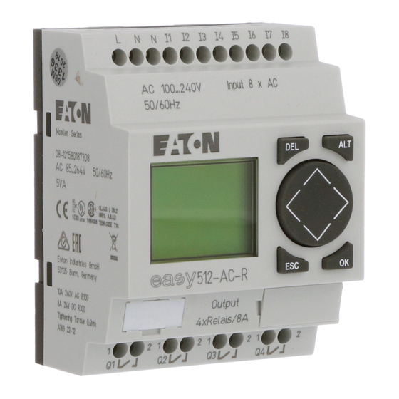
Eaton EASY512-AC-R
Eaton EASY512-AB-RCX
Eaton EASY512-AB-RC
Eaton EASY512-DC-RCX
Eaton EASY-E4-DC-16TE1
Eaton EASY412-AC Series
Eaton EASY719 RC Series
Eaton EASY410-DC Series
Eaton EASY620-DC-TE
eaton Categories
UPS
Circuit breakers
Switch
Industrial Equipment
Industrial Electrical
More eaton Manuals
Login
Sign In
OR
Sign in with Facebook
Sign in with Google
Upload manual
Upload from disk
Upload from URL