Sign In
Upload
Manuals
Brands
Omron Manuals
Machine Vision Systems
FZ5-8 series
Omron FZ5-8 series Manuals
Manuals and User Guides for Omron FZ5-8 series. We have
2
Omron FZ5-8 series manuals available for free PDF download: User Manual, Hardware Setup Manual
Omron FZ5-8 series User Manual (582 pages)
Brand:
Omron
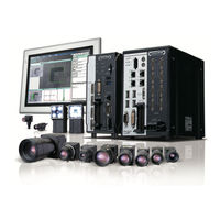
| Category:
Machine Vision Systems
| Size: 28.22 MB
Table of Contents
Table of Contents
16
Sections in this Manual
17
Contents
17
Terms and Conditions Agreement
24
Warranty, Limitations of Liability
24
Safety Precautions
26
Precautions for Safe Use
28
Precautions for Correct Use
33
Regulations and Standards
39
All Series
39
FH-1000/2000/3000/5000 Series
39
FH-L Series
40
FHV Series
41
FZ5 Series/Fz5-L Series
41
Revision History
42
Overview
43
Checking the System Configuration
44
System Configuration
44
Functional Comparison between the FH-Series, FHV-Series and FZ5-Series Controllers
45
Flow of Application
49
Features
51
Basic Mechanism for Measurements
52
Support for a Variety of Scenes and Measurement Lines
54
Basic Operations
57
Preparing the Controller and Cameras
58
Camera Setup
58
Preparing a Controller
60
Adjusting the Camera
61
Basic Knowledge about Operations
62
Inputting Values
62
Inputting Text
63
Selecting Files and Folders
66
Available Operations in Select File Window
69
Using the Zoom Function
70
Setting Figures
71
Changing the Image Mode and Other Display Contents
80
Changing the Display Ratio
81
Checking System Information
83
Checking the Memory Consumption and Percentage of Memory Used
87
Capturing Screen Images
88
Saving Settings before Turning off the Power and Restarting
90
Saving the Setting to the Controller [Data Save]
90
Device Information Storage Tool
91
Restarting the Controller: [System Restart]
93
Initializing the Controller
95
Turning off the LCD
97
Turning off the LCD [LCD OFF]
97
Restoring Power to the LCD
97
Setting the Controller
99
Selecting Language [Startup Settings]
100
Setting the Status at Startup [Startup Settings]
101
Setting Communication [Startup Settings]
104
Setting Operation Mode [Startup Settings]
110
Setting the Operation Mode
111
Parallel Processing
127
Checking the Camera Connections: [Camera Connection]
137
Setting the Trigger Delay [Inter-Camera Setting]
138
Setting the SHTOUT Signal [Output Signal Settings]
141
Setting the Conditions Related to Communications
144
Setting Date/Time [Date/Time Settings]
145
Setting Fan Control [Fan Control Setting]
147
Setting]
147
Setting the Pulse Width for the STEP Input Detection [STEP Signal Filter Setting]
148
Setting Encoder Trigger [Encoder Trigger Setting]
149
Setting Network Drive [Network Drive Setting]
151
Setting Screen Capture [Screen Capture Setting]
155
Setting the Conditions that Are Related to Operation During Measurement [Measurement Conditions]
156
Setting Logging Conditions [Logging Setting]
158
Setting Operation Log [Operation Log Setting]
159
Setting the Operation at Error [Error Operation Setting]
160
Setting Character Code Using Macro/Variable Function [Macro/Variable Function Setting]
162
Setting Character Code Using Macro/Variable Function
162
Function Setting]
162
Creating Measurement Scenes
164
What Is a Scene
164
Creating a Scene
167
Editing Processing Units in Scenes
169
Displaying and Checking Processing Branches in a Scene
172
Using Variables to Edit the Flow [TDM Editor]
176
Edit Flow Screen
176
Editing Processing Units in a Scene
186
Editing Scenes
196
Using Variables
205
Executing Test Measurements
233
Key Points for Adjustment
235
Stabilizing Measurements
235
Shortening Processing Time
237
Useful Functions for Operation
238
Logging Measurement Values and Measurement Images [Data Logging/Image Logging]
238
Logging Measurement Values and Measurement Images
238
Saving Data to an External Device [Ftp/Network Drive]
254
Useful Functions for Operation
257
Remeasuring Saved Images [Remeasurement]
257
Improving Adjustment Efficiency [Judgement Result Monitoring]
258
Analyzing Inspection and Measurement Results [NG Analyzer]
259
Layout of NG Analyzer Window
260
Using Method of NG Analyzer
263
Saving Measurement Values
265
Changing Judgement Conditions Without Stopping Measurement [Simplified Non-Stop Adjustment]
265
Changing Regions as a Batch [Shift Area]
267
Updating the Reference Position Data for a Unit in the Measurement Flow [Update Standard Position Tool]
268
Monitoring Measurement Value Trends [Trend Monitor]
269
Clearing Measurement Results [Measurement Clear]
271
Clearing Saved Images [Logging Image Clear]
271
Managing Images Used for Model Registration and Reference [Registered Image Manager]
272
Specifying the Destination to Save
272
Registering Images
274
Renaming Image Names
275
Deleting Images
276
Loading Images
276
Verifying Calibration Results [Calibration Support Tool]
277
Data Setting
277
Increasing/Switching Measurement Scenes
279
What Is a Scene Group
280
Switching the Scene or Scene Group
282
Switching the Scene
282
Switching Scene Groups
282
Editing Scenes [Scene Maintenance]
284
Copying Scenes
284
Deleting Scenes
284
Renaming a Scene and Adding a Description
285
Editing Scene Groups [Scene Maintenance]
286
Copying and Deleting Scene Groups
286
Renaming the Scene Group Name
287
Saving Scene Groups in External Storage [Scene Group Saving Destination Settings]
288
Increasing the Number of Scenes in a Group to more than 128 Scenes [Conversion Scene Group Data Tool]
290
Section 8 Setting Windows
297
Windows
297
Types of Windows
297
Overview of Window Navigation
298
Main Window (Layout 0): Adjustment Window (Default)
299
Main Window (Layout 1): Run Window (Default)
304
Adjustment Windows and Run Windows
305
Main Window (Layout 0): Adjustment Window (Default)
305
Main Window (Layout 1): Run Window (Default)
306
Main Window (Layout 1): Switching to the Run Window
306
Main Window (Layout 1): Switching to the Adjustment Window
307
Arranging Windows [Layout Functions]8-14
308
Arranging Window Elements (Layout Modification)
308
Arranging Windows [Layout Functions]
308
Setting the Behavior of Output Signals for each Layout [Layout Settings]
319
Switching Layout Numbers in the Main Window [Layout Switching]
320
Judgement Pane
321
Information Pane
321
Toolbox Pane
322
Measurement Pane
324
Flow Display Pane
324
Detail Result Pane
325
Image Container Pane
326
Error Pane
329
Image File Display Pane
331
Label Pane
333
Extended Window Parts
334
Login Account Display Window (Mdi_Disploginuser.dll)
334
Data Grid Window (Mdi_Datagrid.dll)
335
Login Account Display Window (Mdi_Disploginuser.dll)
341
Setting Dialog Box Display Button Window (Mdi_Dispsetupbtn.dll)
342
Text Display Window (Mdi_Disptext.dll)
345
Custom Dialog Display Button Window (Mdi_Executebtn.dll)
347
Macro Trigger Window (Mdi_Mcrtrigger.dll)
350
Message Box Display Window (Mdi_Msgbox. Dll)
351
Value Input Window (Mdi_Numbox.dll)
352
Data Settings Button Window (Mdi_Setdatabtn.dll)
354
Simple Data Grid Window (Mdi_Simpledatagrid.dll)
357
Troubleshooting
360
Creating a Custom Dialog Box [Custom Dialog Functions]8-67
361
Flow of Use
361
Creating a Custom Dialog Box [Custom Dialog Functions]
361
Custom Dialog Tool
361
Custom Dialog Tool
362
Launching Your Custom Dialog Box
380
Saving/Loading Data
381
Saving Data to the FH Series/Fz5 Series
383
About Saving Areas
383
External Drive Names
385
Using External Storage Devices
386
Shared Folder on a Computer Connected to the Network
386
Saving Settings Data to the Flash Memory
387
Saving Setting Data to the Controller Ramdisk or an External Storage Device
388
Saving Setting Data to the Controller Ramdisk or an External
388
Storage Device
388
Saving Logged Images in the Controller Memory (RAM) to a Ramdisk or an External Storage Device
390
Copying or Moving Files between the Controller Ramdisk and an External Storage Device
392
Loading Settings Data from the Controller Ramdisk or an External Storage Device to the Sensor Controller
393
Backing up Sensor Controller Setting Data [Configuration Copy]
395
Before Backing up
395
Backing up Sensor Controller Settings
397
Restoring Saved Settings
407
Troubleshooting
410
Copying Settings for each Line in Multi-Line Random-Trigger Mode [Line Maintenance]
412
Copying Settings for each Line in Multi-Line Random-Trigger
412
Mode [Line Maintenance]
412
Before Use of Line Maintenance
413
Line Maintenance Tool Operations
416
Operating with Functional Limitations
424
Troubleshooting
427
Saving Image Files to a Ramdisk or an External Storage Device [Image File Save]
428
Saving Image Files to a Ramdisk or an External Storage Device
428
Outputting a List of Scene Data Setting Values [Setting Values Download/Upload Tools]
431
Downloading Setting Values
431
Outputting a List of Scene Data Setting Values
431
About Downloaded CSV Files
432
Uploading Setting Values
433
Saving/Loading Layout Settings [Layout Upload, Download Tool]
435
Advanced Usage
437
Remotely Operating the Controller [Remote Operation]
439
Environment Settings
441
Connection Method for Remote Operation
446
Terminating Remote Operation
449
Differences from Local Operation and Limitations
450
Multi-Trigger Imaging Processing with any Timing [Multi-Trigger Imaging]
451
Multi-Trigger Imaging Processing with any Timing
451
[Multi-Trigger Imaging]
451
Settings for Multi-Trigger Imaging
452
Restrictions
453
Restrictions
454
Setting Methods
455
About Multi-Input Function (Multi-Trigger Imaging)
459
Troubleshooting
464
Limiting User Operations [Security Settings]
465
Setting Accounts (Account List)
465
Setting Layout Restrictions
469
Setting User Group Operation Restrictions
470
Saving/Loading/Deleting the Security Settings
472
Recording the Operation History [Operation Log]
476
Using the Operation Log
476
Operation Log Format
479
Setting the Keyboard Layout for the Controller [Keyboard Layout Selection Tool]
480
Setting the Keyboard Layout for the Controller
480
Switching User Accounts
481
Logging in
481
Logging out
482
Customizing Communication Commands [Communication Command Macro]
483
Extending the Functions in a Measurement Flow or Scene [Scene Control Macro Tool]
484
Positioning Workpieces for Stage and Robot Applications [Alignment Function]
485
Overview
485
Positioning Workpieces for Stage and Robot Applications
485
[Alignment Function]
485
Execution of Calibration
488
Troubleshooting
495
Alignment
496
Alignment Processing Items
503
Section 11 What to Do!
506
Error Messages and Troubleshooting
506
Faq
513
During Start-Up
513
During Operation
514
For Measurement
515
About Parallel Interface
516
Serial Interface (RS-232C/422 Connection)
517
Camera with Lighting Controller
518
Appendices
519
Menu List
520
External Tool List
523
FHV Series Processing Items
524
FHV Series Tools
527
Measurement Mechanism
528
A-5-1 Color Processing Mechanism
528
Color Processing Mechanism
528
A-5-2 Search Processing Mechanism
529
A-5-3 Edge Detection Measurement
532
A-5-4 Defect Detection Measurement
536
A-5-5 Handling Coordinates
537
Image File
538
About Number of Logging Images
541
About Max. Number of Loading Images During Multi-Input
545
About Memories Usable with FH Series/Fz5 Series
547
Memory Usage Guidance for Processing Items
548
Memory Display Image on PLC I/O
553
Sharing Data Within the Controller [User Data Tool
555
A-12-1 Setting Procedure for User Data
555
About Limits on the Number of Image Input Processing Items Used
557
Operation Log Input Information List
558
Character Code Table
571
List for Processing Item Identifier
572
Advertisement
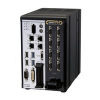
Omron FZ5-8 series Hardware Setup Manual (260 pages)
Vision Sensor
Brand:
Omron
| Category:
Industrial Equipment
| Size: 48.52 MB
Table of Contents
Introduction
3
Intended Audience
3
Applicable Products
3
Relevant Manuals
4
Manual Structure
6
Page Structure
6
Special Information
7
Sections in this Manual
9
Table of Contents
10
Terms and Conditions Agreement
14
Warranty, Limitations of Liability
14
Application Considerations
15
Disclaimers
15
Safety Precautions
16
Precautions for Safe Use
18
Precautions for Correct Use
21
Regulations and Standards
24
All Series
24
FH-1000 and FH-3000 Series
25
FH-L Series
26
FZ5 and FZ-L Series
27
Related Manuals
28
Terminology
29
Revision History
33
Confirm the Package
35
Sensor Controller
36
FH-3 Series
36
10 / FH-3-10 Series
36
FH-1-20 / FH-3-20 Series
37
FH-L Series
37
FH-L-10 Series
38
FZ5-12 / FZ5-11 / FZ5-60 / FZ5-8 Series
38
FZ5-L35 Series
39
FZ5-L35-10 Series
39
Sold Separately
40
Cameras and Related
40
Monitor
42
Lighting and Lighting Controller
42
Accessories
43
Cable
44
Software
46
Overview of System
48
Basic System of Measurement
48
FH-1000/FH-3000 Series
50
FH-L Series
51
FZ5 Series
51
FZ5-L Series
52
System Configuration
53
FH-1000/FH-3000 Series
53
FH-L Series
54
FZ5-600/FZ5-800/FZ5-1100/FZ5-1200 Series
55
FZ5-L Series
56
Flow of Use Procedure
57
Sensor Controller
60
FH-1000/FH-3000 Series
60
FH-L Series
66
FZ5-600/FZ5-800/FZ5-1100/FZ5-1200 Series
71
FZ5-L Series
81
Camera
85
High-Speed Digital CMOS Camera (FH-S Camera Series)
85
Digital CMOS Cameras: FH-S Camera Series
89
Digital CCD/CMOS Cameras: FZ-S Camera Series
90
High-Speed Digital CCD Cameras : FZ-SH Camera Series
94
Small Digital CCD Cameras: FZ-S Camera Series
95
Intelligent Compact Digital CMOS Camera: FZ-S Camera Series
98
Camera Cable
101
Camera Cables and Right-Angle Camera Cable
101
Bend Resistant Camera Cable and Bend Resistant Right-Angle Camera Cable
102
Long-Distance Camera Cable and Long-Distance Right-Angle Camera Cable
103
Cable Connection Table
104
Cable Extension Units
106
Lens
109
C-Mount Lens for 1/3-Inch Image Sensor
109
C-Mount Lens for 2/3-Inch Image Sensor
110
C-Mount Lens for 1-Inch Image Sensor
111
M42-Mount Lens for Large Image Sensor
112
Lenses for Small Camera
112
Vibration and Shock Resistant C-Mount Lens for 2/3-Inch Image Sensor
113
High-Resolution Telecentric Lens for C-Mount Lens for 2/3-Inch Image Sensor
116
Extension Tubes
118
Meaning of Optical Chart
119
Lighting, Lighting Controller, and Cables
128
Touch Panel Monitor and Cable
129
LCD and Cable
135
Sysmac Studio
138
All Series
140
FH-1000/FH-3000 Series
142
FH-L Series
143
FZ5 Series
144
FZ5-L Series
145
Setup and Wiring
147
When Turning on and off
149
All Series
149
FH-1000/FH-3000 Series
151
FH-L Series
151
FZ5 Series
151
FZ5-L Series
151
Fail-Safe Measures
152
Sensor Controller Installation
153
All Series
153
FH-1000/FH-3000 Series
154
FH-L Series
158
FZ5 Series
168
FZ5-L Series
172
Setup Touch Panel Monitor or Monitor
174
All Series
174
FH-1000/FH-3000 Series
174
FH-L Series
175
FZ5 Series
175
FZ5-L Series
175
Camera Installation
176
All Series
176
FH-L Series
178
FZ5 Series
178
FZ5-L Series
179
Insert SD Memory Card or USB Memory
180
FH-L Series
181
FZ5 Series
181
Use by Connecting Software
182
Sysmac Studio FH Tool
182
FZ_FH Remote Operation Tool
182
Simulation Software
182
Installation in a Control Panel
183
All Series
183
FH-L Series
187
FZ5 Series
195
FZ5-L Series
197
Parallel Interface
200
All Series
200
FH-1000/FH-3000 Series
201
FH-L Series
208
NPN Input/Output for FZ5 Series
215
PNP Input/Output for FZ5 Series
221
FZ5-L Series
227
Other (Parallel Converter Cable)
231
Encoder Interface
242
Ethercat Interface
245
Ethernet Interface
247
FH-1000/FH-3000 Series
248
FH-L Series
250
FZ5 Series
252
FZ5-L Series
253
Serial Interface
255
All Series
255
FH-1000, FH-3000, and FH-L Series
256
FZ5 Series
257
FZ5-L Series
258
Advertisement
Related Products
Omron FZ5-12 series
Omron FJ-3005
Omron FJ-H3000
Omron FJ-H3005
Omron FJ-H3050
Omron FJ-H300 Series
Omron FJ-H300 10 Series
Omron F210-C10
Omron F150-S1A
Omron F160-SLC20
Omron Categories
Blood Pressure Monitor
Controller
Accessories
Switch
Inverter
More Omron Manuals
Login
Sign In
OR
Sign in with Facebook
Sign in with Google
Upload manual
Upload from disk
Upload from URL