User Manuals: Omron FHV7 series Machine Vision System
Manuals and User Guides for Omron FHV7 series Machine Vision System. We have 4 Omron FHV7 series Machine Vision System manuals available for free PDF download: User Manual, Setup Manual, Construction Manual
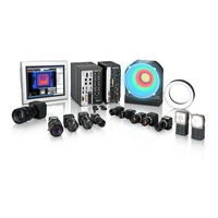
Omron FHV7 series User Manual (582 pages)
Vision Sensor
Brand: Omron
|
Category: Machine Vision Systems
|
Size: 26 MB
Table of Contents
-
-
-
-
All Series33
-
FH-L Series34
-
FHV Series35
-
-
Terminology
39 -
-
Features55
-
-
What Is a Scene
174 -
Creating a Scene
177 -
-
-
Setting Windows303
-
-
Windows
303 -
-
Judgement Pane324
-
Information Pane324
-
Toolbox Pane325
-
Measurement Pane327
-
Error Pane333
-
Label Pane336
-
Troubleshooting363
-
Advanced Usage
439 -
-
Logging in486
-
Logging out487
-
-
What to Do
507 -
Appendices
521-
A-1 Menu List
523 -
-
Measurement528
-
Input Image528
-
A-4-5 Branch529
-
A-6 Image File
541 -
-
A-8-1 FH Series547
-
A-8-2 FHV Series547
-
FH Series547
-
-
Advertisement
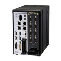
Omron FHV7 series User Manual (582 pages)
Brand: Omron
|
Category: Machine Vision Systems
|
Size: 28 MB
Table of Contents
-
Contents
17 -
-
-
Setting]147
-
-
-
What Is a Scene
164 -
Creating a Scene
167
-
Windows
297 -
-
Judgement Pane321
-
Information Pane321
-
Toolbox Pane322
-
Measurement Pane324
-
Error Pane329
-
Label Pane333
-
Troubleshooting360
-
-
Flow of Use361
-
-
Advanced Usage437
-
-
-
-
Logging in481
-
Logging out482
-
-
Faq
513 -
Appendices
519 -
Menu List
520 -
FHV Series Tools
527 -
Image File
538
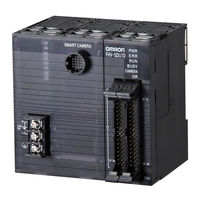
Omron FHV7 series Setup Manual (246 pages)
Smart Camera
Brand: Omron
|
Category: Digital Camera
|
Size: 24 MB
Table of Contents
-
Disclaimers15
-
Warning18
-
Mounting21
-
Others22
-
Maintenance24
-
Beam24
-
Image Sensor24
-
Warm-Up25
-
Others25
-
LED Safety26
-
Terminology29
-
Smart Camera36
-
Cables39
-
Modules43
-
Accessories44
-
Software47
-
Smart Camera61
-
FHV Series61
-
Dimensions66
-
Cables75
-
I/O Cables75
-
Lens Modules101
-
Specifications101
-
Optical Chart105
-
C Mount Lenses109
-
Specifications109
-
Lighting Modules126
-
Specifications126
-
Dimensions127
-
Optical Filters128
-
Specifications128
-
Dimensions128
-
Waterproof Hoods130
-
Specifications130
-
Dimensions131
-
Specfications135
-
Dimensions135
-
Specifications137
-
Dimensions137
-
Specifications139
-
Dimensions139
-
Specifications141
-
Dimensions141
-
Specifications142
-
Dimensions142
-
Specifications144
-
Dimensions144
-
3-15 Software145
-
Sysmac Studio145
-
Warning148
-
Installation151
-
How to Connect171
-
Cables185
-
Pin Layout190
-
Cables198
-
Pin Layout202
-
Pin Layout206
-
Installation220
-
Windows221
-
Use Procedures222
-
Introduction236
Advertisement
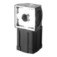
Omron FHV7 series Construction Manual (119 pages)
Vision Sensor Robot Vision Application
Brand: Omron
|
Category: Accessories
|
Size: 3 MB
Table of Contents
Advertisement