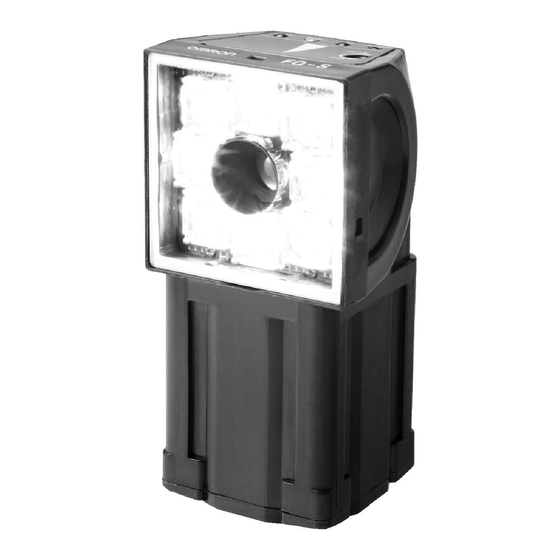
Omron FH Series Construction Manual

Omron FH Series Construction Manual

Vision sensor robot vision application
Hide thumbs Also See for FH Series:

Advertisement

Quick Links

Vision Sensor
FH/FHV Series
Robot Vision Application
Construction Guide
OMRON Corporation Edition

Advertisement

Table of Contents
loading

Summary of Contents for Omron FH Series

  • Page 1 Vision Sensor FH/FHV Series Robot Vision Application Construction Guide OMRON Corporation Edition...
  • Page 2: Table Of Contents

    TABLE OF CONTENTS INTRODUCTION ............................1 TERMS AND CONDITIONS AGREEMENT ................... 2 SOFTWARE LICENSE AGREEMENT ......................5 REGULATIONS AND STANDARDS ...................... 12 SAFETY PRECAUTIONS ......................... 13 OVERVIEW ............................16 1.1. VERVIEW ............................16 1.2. ARGET EADERS ..........................18 SYSTEM CONFIGURATION ......................19 2.1.
  • Page 3 7.7. ISCONNECTING ISION ENSOR FROM OBOT ONTROLLER ............112 REFERENCE INFORMATION ...................... 113 REVISION HISTORY ........................114...
  • Page 4 Copyrights and Trademarks Microsoft product screen shots reprinted with permission from Microsoft Corporation. Windows is either registered trademarks or trademarks of Microsoft Corporation in the United States and other countries. Other company names and product names in this document are the trademarks or registered trademarks of their respective companies.
  • Page 5: Introduction

    Introduction Thank you for purchasing the FH/FHV. This manual provides information regarding functions, performance, and operating methods that are required for using the FH/FHV Series product. When using the FH/FHV Series product, be sure to observe the following: The FH/FHV Series product must be operated by personnel knowledgeable in ...
  • Page 6: Terms And Conditions Agreement

    (a) Exclusive Warranty. Omron’s exclusive warranty is that the Products will be free from defects in materials and workmanship for a period of twelve months from the date of sale by Omron (or such other period expressed in writing by Omron). Omron disclaims all other warranties, express or implied.
  • Page 7 It may represent the result of Omron’s test conditions, and the user must correlate it to actual application requirements. Actual performance is subject to the Omron’s Warranty and Limitations of Liability.
  • Page 8 proofreading errors or omissions. Even if it conforms to all instructions in this safety guide, it isn't possible to guarantee that a robot system will be free from an accident resulting in injury or death or considerable damage to property caused by the industrial robot. It is the customer's responsibility to implement appropriate security measures based on their own risk assessment.
  • Page 9: Software License Agreement

    Licensee, only when you agree to the SOFTWARE LICENSE AGREEMENT (this “Agreement) set forth below. This Agreement is a legal agreement between you and OMRON Corporation. By breaking the seal of this package, clicking “I Agree”, downloading, installing, copying or otherwise using this Licensed Software, you agree to be bound by and comply with the terms and conditions of this Agreement.
  • Page 10 GRANT Section 2 Subject to the terms and conditions in this Agreement, Omron hereby grants to Licensee the following limited, revocable, non-transferable, non-exclusive and “as-is” to use, copy, modify and sublicense the Licensed Software.
  • Page 11 Omron has no obligation to provide any support or engineering assistance of any sort to Licensee. The terms and conditions in this Agreement shall govern the Licensed Software that Licensee has copied, modified and/or sublicensed.
  • Page 12 Section 4 THE LICENSED SOFTWARE IS PROVIDED AS A CONVENIENCE AND ACCOMMODATION TO LICENSEE. TO THE EXTENT NO PROHIBITED BY LAW, IN NO EVENT SHALL OMRON, ITS AFFILIATES, OR ANY OF ITS OR THEIR RESPECTIVE DIRECTORS, OFFICERS, EMPLOYEES, OR AGENTS, BE LIABLE TO LICENSEE OR ANY THIRD PARTY FOR ANY...
  • Page 13 Omron Indemnitees as a result of (a) a breach of this Agreement by Licensee, (b) Licensee’s violation of applicable law, or (c) the negligence or other wrongful conduct of Licensee.
  • Page 14 Licensee shall immediately (i) cease using the Licensed Software in any manner, (ii) return to Omron or destroy under Omron’s instruction the Licensed Software (including all copies thereof) to Omron.
  • Page 15 10.11 Omron may, at its discretion, change this Agreement at any time by any reason. Licensee is deemed to agree to all provisions of the changed Agreement if Licensee...
  • Page 16: Regulations And Standards

    Regulations and Standards The FH/FHV Vision Sensor Controllers do not conform to laws and regulations relating to the safety of industrial robot application. When you use the FH/FHV Vision Sensor Controllers in robot systems that use industrial robots, be sure to verify the conformance to laws and regulations relating to the safety of industrial robot application.
  • Page 17: Safety Precautions

    Safety Precautions ●Symbols and the meanings for safety precautions described in this manual. In order for the product to be used safely, the following indications are used in this book to draw your attention to the cautions. The cautions with the indications describe the important contents for safety.
  • Page 18 Precautions for Correct Use Precautions on what to do and what not to do to ensure proper operation and performance. Additional Information Additional information to read as required. This information is provided to increase understanding or make operation easier. ●Alert statements in this Manual The following alert statements apply to the products in this manual.
  • Page 19 Please take external safety measures so that the system as a whole should be on the safe side even if a failure of a Sensor Controller or an error due to an external factor occurred. An abnormal operation may result in serious accident. Please take fail-safe measures on your side in preparation for an abnormal signal due to signal conductor disconnection and/or momentary power interruption.
  • Page 20: Overview

    Overview 1.1. Overview This document describes procedures for connections and settings required for constructing robot vision applications by connecting your robot controller to the Vision Sensor FH/FHV (hereafter referred to as Vision Sensor). Utilizing this document at startup can reduce man-hours to connect the Vision Sensor to your robot controller, set the Vision Sensor, and create robot programs.
  • Page 21 an amount of the position deviation from the reference position, and outputs a robot position compensated from the reference position for the workpiece position to the robot controller. Imaging (Measurement) Grip Correction When combining the Grip Correction and Place, the Vision Sensor outputs a placing position considering positioning deviation to the robot controller.
  • Page 22: Target Readers

    1.2. Target Readers Target readers for this document are who are responsible for connecting the Vision Sensor and the robot controller, executing calibration between a camera and a robot using the robot control by the Vision Sensor, and construct robot vision applications. Additionally, the readers need to have understood the use and implementation methodology for robot programs of the targeted robot controller.
  • Page 23: System Configuration

    System Configuration This chapter describes the system configuration and target devices to construct robot vision applications. 2.1. When using Vision Sensor FH Series System Configuration 2.1.1. IP address IP address Switching hub 10.5.5.100 10.5.5.102 LAN cable (Straight cable) Vision Sensor...
  • Page 24: When Using Vision Sensor Fhv Series

    Please contact Data set output tool for OMRON - us for how to Robot vision obtain it. PC software Software OMRON - Ver. 3.7 or later Automation Control Environment (ACE) Switching Recommended OMRON Industrial switching hub W4S1-□□□ product FZ-MEM2G Recommended...
  • Page 25 1720□-36000 Vertical multi-joint robot 1720□-36020 Viper 650 1720□-36010 Robot OMRON 1720□-38000 Viper 850 1720□-38020 1720□-38010 Teaching OMRON Teaching pendant T20 10046-010 pendant Please contact Data set output tool for OMRON - us for how to Robot vision obtain it. PC software...
  • Page 26: Startup Procedures

    Startup Procedures This chapter describes the work flow, preconditions, and what can be achieved by Startup Procedures in each chapter. 3.1. Work Flow Please follow the flow below for constructing robot vision applications Creating data set for the robot vision ▼...
  • Page 27 Connecting Vision Sensor and Robot Controller 3.2.2. When following the procedures in Chapter 5, you can complete necessary settings for communications by loading environment data to the Vision Sensor and robot programs to the robot controller. Additionally, executing a robot program for startup establishes TCP/IP connection between the Vision Sensor as a server and the robot controller as a client.
  • Page 28 Switching hub 1) Control command Vision Sensor 3) Command response (Current position etc.) Execution obot program for startup 2) Command execution Robot Robot controller (Driving the robot etc.) Designing Robot Programs 3.2.4. Described in the following figure, when following the procedures in Chapter 7, you can understand an implementation methodology for robot programs to control the Vision Sensor such as switching scenes or executing measurements by running robot programs in the robot controller described in the following figure.
  • Page 29: Preconditions

    3.3. Preconditions The following conditions shall be satisfied. The installation, wiring, and operation verification for each device have been finished. The robot controller is in auto mode and the high-power is turned on. Additional Information This document does not provide operations, installation, and wiring methods for each device.
  • Page 30: Creating Data Set For Robot Vision

    Creating Data Set for Robot Vision This chapter describes procedures to create robot programs (sample program) for the robot controller and data (environment data) for the Vision Sensor to construct robot vision applications. Please follow the flow below for the settings. Select robot manufacturer...
  • Page 31 Click [Output] after selecting the output path for the data set. Click [OK] when the “Check” dialog is displayed after the data set was output. Check that a folder was created with a name of “year, month, day, hour, minute, and second” in the specified output path and there “FHdata”...
  • Page 32: Connecting Vision Sensor To Robot Controller

    5. Connecting Vision Sensor to Robot Controller This chapter describes procedures to connect the Vision Sensor to the robot controller. Please follow the flow below for the settings. To reflect the communication settings, Setting communications for the load the environment data created by the Vision Sensor data set output tool for the robot vision, and then restart the Vision Sensor.
  • Page 33: Setting Communications For Vision Sensor

    5.1. Setting Communications for Vision Sensor Please follow the procedures below to set the communications for the Vision Sensor. Select [Tool] - [Configuration copy] in the menu bar. Select “Select sensor controller project” in the [Load] tab. Select the FHdata folder in the folder outputted by using the data set output tool for the robot vision.
  • Page 34: Setting Communications For Robot Controller

    5.2. Setting Communications for Robot controller Please follow the procedures below to set the communications for the robot controller. Press [MENU] on the teaching pendant to display the right figure (HOME1 window). Select [Next>] - [Next>] - [Maint] - [Info] and then refer to the IP address for the robot controller SYSTEM...
  • Page 35 The dialog shown on the right will be displayed, set the IP address and the subnet mask for the PC so that the IP address and network part of the referred robot controller are the same but the host part is different.
  • Page 36 right dialog will displayed, select “SYSTEM SECTION” in the “Section” area “ipaddress” “Statements” area and click [Edit]. right dialog will displayed, change ipaddress and click [Accept]. Set the IP address not to overlap with other devices. Change the IP address of the PC again based on the changed one for the robot controller.
  • Page 37: Connecting And Checking Vision Sensor And Robot Controller

    Connecting and Checking Vision Sensor and Robot Controller Follow the procedures below to connect the Vision Sensor and the robot controller and to check the connection status. Verifying Ethernet Communication (FH Series Vision Sensor) 5.3.1. Connect the Vision Sensor and the robot controller with LAN cables.
  • Page 38 When 32-byte data cannot be sent/received four times and PING command timed out, check whether or not the robot controller is turned on, the wiring was correctly done, or communication settings correct. Verifying Ethernet Communication (FHV Series Vision Sensor) 5.3.2. Connect vision sensor,...
  • Page 39 When 32-byte data cannot be transmitted/received four times PING command timed out, check whether or not the robot controller is turned on, the wiring was correctly done, communication settings correct. (Operation of the PC) Execute PING command to the IP address of the Vision Sensor. (Operation of the PC) When 32-byte data could be successfully...
  • Page 40 Verify Commands Sent/Received 5.3.3. (Operation of ACE) Click an icon enclosed in red square on the right figure to display the monitor window. Click an icon enclosed in red square on the right figure to display the robot jog operation dialog.
  • Page 41 Like shown on the right figure, if an error message is displayed on the ACE’s monitor window, connection failed. Check the wiring and others. (Operation of the Vision Sensor and ACE) Like shown on the right figure, when [Get] is clicked on the Main Window of the Vision Sensor and the current position of the robot on ACE's monitor...
  • Page 42: Setting Vision Sensor

    Setting Vision Sensor This chapter describes by each application type, the setting procedures for the Vision Sensor required for constructing robot vision applications. Application Where to find Pick/Place with a fixed camera Chapter 6.2 Grip Correction with a fixed camera Chapter 6.3 Pick/Place with an on-hand camera Chapter 6.4 6.1.
  • Page 43 User Dialog 6.1.2. On the Main Window of the Vision Sensor, launch buttons for the user dialog are arranged like below. Dialog name Description Sets the jog operation, target position movement, and Robot Operation operation speed and so on. Calibrates a camera and the robot automatically with Calibration operations of the Vision Sensor.
  • Page 44 This is the robot reference position when imaging (measuring) workpieces. Imaging (Measurement) Robot Image Robot Image Robot Image Position Position (Robot Position (Robot Image Pos.) (Robot Image Image Pos.) Workpiece �� �� Pos.) �� �� Imaging Workpiece (Measurement) �� �� Robot Base Robot Base Position Position...
  • Page 45 Robot Grip This is the reference position of the robot at picking or placing a Position (Robot workpiece. This is the robot position when the robot gripped the Grip Pos.) workpiece located in its reference position. In the case of Pick and Place, this is the reference position on the robot side to calculate the relative positional relationship between the workpiece and the robot.
  • Page 46 Robot Operation Dialog Robot Operation Setting Dialog In the robot operation dialog, the following items are possible to do using basic functions for operating the robot by operations of the Vision Sensor. Function Description Execute the jog operation of the robot. By clicking [Jog operation], the robot is operated according to the settings in the Jog operation jog operation setting.
  • Page 47 * For each coordinate system, the orientation of each axis differs depending on the robot manufacturer and axis configuration. For the detailed definition of the coordinate systems, please refer to the manual of your robot. [World coordinate system] The base of the robot is the reference position in this coordinate system.
  • Page 48 �� �� �� �� �� �� 6-axis robot �� �� �� �� �� �� 4-axis robot Communication The timeout for communications between the Vision Sensor and settings (Comm. the robot controller can be set. setting) WARNING Clicking [Jog operation] or [Robot move] drives the robot. Operate the robot in the state whereby pressing the [Emergency stop] button can stop its motion anytime.
  • Page 49 Precautions for Correct Use Even if the robot controller changes the reference position from the flange of the tool coordinate system, it will not be reflected to the jog operation setting of the Vision Sensor. These features are only available in a connection status that is established between the Vision Sensor and the robot controller with TCP no-procedure protocol invoked by steps in Chapter 5.3.
  • Page 50: Pick/Place With Fixed Camera

    6.2. Pick/Place with Fixed Camera In the case of Pick/Place with a fixed camera, first calculate the relative positional relationship between the workpiece position and the actual robot position according to the workpiece reference position and the robot grip position. Second, output to the robot controller the robot command position o or picking or placing he measured workpiece.
  • Page 51 Setting Calibration 6.2.1. Follow the procedures below to set a scene for Calibration. Prepare a calibration target and mount it to the robot. target should have sufficient strength not to shift or deform by operations of the Calibration Target robot. The target should have a mark such as pattern or shape which Shape...
  • Page 52 Click the “0. Camera Image Input FH” icon on the Main Window of the Vision Sensor to open the setting screen. * When using the FHV Series Smart Camera Vision Sensor, delete the "0. Camera Image Input FH" unit and in its place set "Camera Image Input FHV"...
  • Page 53 “Robot Operation” dialog, operate the robot to move the calibration target close to the center of the field of view. * After checking the position, return the image mode from “Through” to “Freeze”. WARNING  These operations drive the robot. ...
  • Page 54 Register it as a model by clicking [OK] after fitting the registering figure calibration target. Click [Edit] on the [Region setting] measurement region according to the field of view for a camera to use. Click [OK] after setting. Click [Measurement] on the [Measurement] tab and check that the “Count”...
  • Page 55 * When using the FHV Series Smart Camera Vision Sensor, select the "Calibration" tab and in the field for "Image Input" select "Camera Image Input FHV". Click [Get] on the Main Window of the Vision Sensor to get the current position of the robot. Click [Calibration] to open the “Calibration”...
  • Page 56 Executing and Checking Calibration 6.2.2. Follow the procedures below to execute and check the calibration. Select [Function] [Clear measurement] on the Main Window menu to clear the previous measurement results. Click [Robot Move] “Calibration” dialog to move the robot to the calibration start position.
  • Page 57 * If stopping this motion on the way, the target measurement may not have been executed correctly. Review the camera settings, model registration, and environment of lightings. WARNING  These operations drive the robot.  Operate the robot in the state whereby pressing the [Emergency stop] button can stop its motion anytime.
  • Page 58 In the [Data setting] tab, set the unit No. to the “3. Vision Master Calibration” to check the relationship between camera and robot coordinate systems from calibration. * Regarding the robot base coordinate system shown on right figure, “Rotation” at the “Standard axis”...
  • Page 59 * When using the FHV Series Smart Camera Vision Sensor, you can use the Simulation Software to load a settings data file that has been saved for backup. This will allow you to launch the "Calibration Support Tool" from the "Tool" menu. For additional information backing...
  • Page 60 Check that the check box for “Output” is not checked. serial data measurement value output until the Vision Sensor setting is completed. Place a check in the check box when executing a robot sample program described in Chapter Click [Robot operation] on the Main Window of the Vision Sensor to open the “Robot Operation”...
  • Page 61 Click [Edit] on the “Robot Ref. Position” dialog to open the “Robot Image Pos.” dialog. Click [Reg. Robot Image Pos.] on the “Robot Image Pos.” dialog to register the current position of the robot. After clicking [Close], check that the “Robot Image Pos.” on the “Robot Ref.
  • Page 62 Select the set camera number tab on the “Camera” tab. Adjust the shutter speed and gain of the camera on the “Camera settings” area. Register a workpiece as a model for Pick/Place on Shape Search III by operations as same as those at step 5 in Chapter 6.2.1.
  • Page 63 After clicking [Close], check that the “Workpiece Ref. Pos.” on the “Robot Ref. Position” dialog has been updated. WARNING An operation of the dialog will automatically set values to Scene and System variables previously set in the scenes loaded by the environment copy feature in Chapter 5.1.
  • Page 64 CAUTION When the robot moves to Z-axis direction, check its motion by visual observation and not by camera image. Click [Get] on the Main Window of the Vision Sensor to get the current position of the robot. Click [Robot Ref. Position] on the Main Window of the Vision Sensor to open the “Robot Ref.
  • Page 65 Click [Edit] for “Robot Approach Dist.” “Robot Ref. Position” dialog to open the “Robot Approach Dist.” dialog. robot approach distance “Robot Approach Dist.”. After clicking [Close], check that the “Robot Approach Dist.” on the “Robot Ref. Position” dialog has been updated. Click [Robot Move] of “Robot Image Pos.”...
  • Page 66 robot produced unexpected motion, please register the robot approach distance again. WARNING  These operations drive the robot.  Operate the robot in the whereby pressing the [Emergency stop] button can stop its motion anytime.
  • Page 67 Checking Application Operations 6.2.4. Follow the procedures below to check that scenes for applications are operable. Click [Robot Operation Check] on the Main Window of the Vision Sensor to open the “Robot Operation Check” dialog. Click [Robot Move] of “Robot Image Pos.” on the “Robot Operation Check”...
  • Page 68 Click [Robot Move] of “Robot Approach Pos.” on the “Robot Operation Check” dialog and move the robot to the approach position. WARNING  These operations drive the robot.  Operate the robot in the whereby pressing the [Emergency stop] button can stop its motion anytime. Click [Robot Move] of “Robot Command Pos.”...
  • Page 69: Grip Correction With Fixed Camera

    6.3. Grip Correction with Fixed Camera For Grip Correction with a fixed camera, calculate a grip deviation amount from the workpiece reference position of a measured workpiece, and outputs to the robot controller the robot command position to correct the grip deviation amount. Precautions for Correct Use When you would like to relatively move the robot to a Place position fixed from the Grip Correction, first correct the position deviation with the grip correction and then...
  • Page 70 Setting Calibration 6.3.1. Follow the procedures below to set a scene for Calibration. Prepare a calibration target and mount it to the robot. target should have sufficient strength not to shift Calibration target or deform by operations of the The target mark is robot.
  • Page 71 Click the “0. Camera Image Input FH” icon on the Main Window of the Vision Sensor to open the setting screen. * When using the FHV Series Smart Camera Vision Sensor, delete the "0. Camera Image Input FH" unit and in its place set "Camera Image Input FHV"...
  • Page 72 Change the image mode to “Through” “Image Window Setting” dialog on the Main Window of the Vision Sensor to display the camera image. Click [Robot Operation] on the Main Window of the Vision Sensor to open the “Robot Operation” dialog. “Robot Operation”...
  • Page 73 Click the “2. Shape search III” icon on the Main Window of the Vision Sensor to open the setting screen. Select a registering figure by clicking [Edit] on the [Model] tab. Register it as a model by clicking [OK] after fitting the registering figure calibration target.
  • Page 74 Click the “3. Vision Master Calibration” icon on the Main Window of the Vision Sensor to open the setting screen. Select the [Sampling setting] tab and set “First calibration setting”, “Effective field view”, “Translation sampling setting”, “Division point number” according actual environment.
  • Page 75 Click [Edit] in the calibration dialog to open the “Calib. Start Pos.” dialog. Check that the dialog displays the current position of the robot and click [Reg. Calib. Start Pos.]. After clicking [Close], check that the “Calib. Start Position” in the “Calib. Start Pos.” dialog has been updated.
  • Page 76 Click [Robot Move] “Calibration” dialog to move the robot to the calibration start position. WARNING  These operations drive the robot.  Operate the robot in the state whereby pressing the [Emergency stop] button can stop its motion anytime. “Calibration” dialog, clicking [SETP Exec.
  • Page 77 Click the “3. Vision Master Calibration” icon on the Main Window of the Vision Sensor to open the setting screen. Select the [Calibration result] tab to check whether or not the “Error evaluation” converged within the accuracy required. Select [Tool] [Calibration support tool] from the menu bar.
  • Page 78 * Regarding the robot base coordinate system shown on right figure, “Rotation” at the “Standard axis” on the “Display setting” Camera tab in the “Calibration support tool” to “Anticlockwise”. If the relation such as directions and camera coordinate origin position between the camera and the robot base coordinate systems is the same as the actual...
  • Page 79 Remove the calibration target from the robot. Setting Applications 6.3.3. Follow the procedures below to set a scene for applications. Click [Scene switch] on the Main Window of the Vision Sensor. Select the target scene, 1 Grip correction_XX Click [OK] to switch scenes.
  • Page 80 Check that the check box for “Output” is not checked. serial data measurement value output until the Vision Sensor setting is completed. Place a check in the check box when executing a robot sample program described in Chapter Click [Robot Operation] on the Main Window of the Vision Sensor to open the “Robot Operation”...
  • Page 81 Click [Get] on the Main Window of the Vision Sensor to get the current position of the robot. Click [Robot Ref. Position] on the Main Window of the Vision Sensor to open the “Robot Ref. Position” dialog. Click [Edit] of “Robot Image Pos.”...
  • Page 82 * When using the FHV Series Smart Camera Vision Sensor, delete the "0. Camera Image Input FH" unit and in its place set "Camera Image Input FHV" as Unit 0. Check the set “Camera No.” by clicking [Select camera] tab. * Change the camera number based actual...
  • Page 83 Click [Edit] on the “Robot Ref. Position” dialog to open the “Workpiece Ref. Pos.” dialog. Click [Reg. Workpiece Ref. Pos.] on the “Workpiece Ref. Pos.” dialog register measurement position of the workpiece. After clicking [Close], check that the “Workpiece Ref. Pos.” on the “Robot Ref.
  • Page 84 Checking Application Operations 6.3.4. Follow the procedures below to check that scenes for applications are operable. advance, robot gripping a workpiece. Click [Robot Operation Check] on the Main Window of the Vision Sensor to open the “Robot Operation Check” dialog. Click [Robot Move] of “Robot Image Pos.”...
  • Page 85 Click [Robot Move] of “Robot Command Pos.” on the “Robot Operation Check” dialog and move the robot to the command position. WARNING  These operations drive the robot.  Operate the robot in the state whereby pressing the [Emergency stop] button can stop its motion anytime. ...
  • Page 86: Pick/Place With On-Hand Camera

    6.4. Pick/Place with On-hand Camera In the case of Pick/Place with an on-hand camera, first calculate the relative positional relationship between the workpiece position and the actual robot position according to the workpiece reference position and the robot grip position. Second, output to the robot controller the robot command position for picking or placing the measured workpiece.
  • Page 87 Setting Calibration 6.4.1. Follow the procedures below to set a scene for Calibration. Prepare a calibration target and locate it as same as the height Calibration of the imaging surface of a Target workpiece. target should have sufficient strength not to shift or deform by operations of the robot.
  • Page 88 Click the “0. Camera image input FH” icon on the Main Window of the Vision Sensor to open the setting screen. * When using the FHV Series Smart Camera Vision Sensor, delete the "0. Camera Image Input FH" unit and in its place set "Camera Image Input FHV"...
  • Page 89 “Robot Operation” dialog, operate the robot to move the calibration target close to the center of the field of view. * After checking the position, return the image mode from “Through” to Freeze”. WARNING  These operations drive the robot. ...
  • Page 90 Click the “2. Shape search III” icon on the Main Window of the Vision Sensor to open the setting screen. Select a registering figure by clicking [Edit] on the [Model] tab. Register it as a model by clicking [OK] after fitting the registering figure calibration target.
  • Page 91 Click the “3. Vision Master Calibration” icon on the Main Window of the Vision Sensor to open the setting screen. Select [Sampling setting] tab “First calibration setting”, “Effective field view”, “Translation sampling setting”, “Division point number” according actual environment. * When using the FHV Series Smart Camera Vision Sensor, select the "Calibration"...
  • Page 92 Check that the dialog displays the current position of the robot and click “Reg. Calib. Start Pos.” After clicking [Close], check that the “Calib. Start Position” in the “Calib. Start Pos.” dialog has been updated. WARNING An operation of the dialog will automatically set values to Scene and System variables previously set in the scenes loaded by the environment copy feature in Chapter 5.1.
  • Page 93 Click [Robot Move] “Calibration” dialog to move the robot to the calibration start position. WARNING  These operations drive the robot.  Operate the robot in the state whereby pressing the [Emergency stop] button can stop its motion anytime. “Calibration” dialog, clicking [SETP Exec.
  • Page 94 Click the “3. Vision Master Calibration” icon on the Main Window of the Vision Sensor to open the setting screen. Select [Calibration result] tab to check whether or not the “Error evaluation” converged within the accuracy required. Select [Tool] [Calibration support tool] from the menu bar.
  • Page 95 In the [Data setting] tab, set the unit No. to the “3 Vision Master Calibration” to check the relationship between camera coordinate system and robot coordinate system got from the calibration. * Regarding the robot base coordinate system shown on right figure, Camera...
  • Page 96 * When using the FHV Series Smart Camera Vision Sensor, you can use the Simulation Software to load a settings data file that has been saved for backup. This will allow you to launch the "Calibration Support Tool" from the "Tool" menu. For additional information backing...
  • Page 97 Setting Applications 6.4.3. Follow the procedures below to set a scene for applications. Click [Scene switch] on the Main Window of the Vision Sensor. Select target scenes. The target scenes are as follows. Pick: 0. Pick_On-hand_xx Place: 2. Place_On-hand_xx Click [OK] to switch scenes. Check that the check box for “Output”...
  • Page 98 Move the robot to a position to image (measure) workpiece for Pick/Place on the “Robot operation” dialog. WARNING  These operations drive the robot.  Operate the robot in the state whereby pressing the [Emergency stop] button can stop its motion anytime. Click [Get] on the Main Window of the Vision Sensor to get the current position of the robot.
  • Page 99 Click [Reg. Robot Image Pos.] on the “Robot Image Pos.” dialog to register the current position of the robot. After clicking [Close], check that the “Robot Image Pos.” on the “Robot Ref. Position” dialog has been updated. WARNING An operation of the dialog will automatically set values to Scene and system variables previously set in the scenes loaded by the environment copy feature in Chapter 5.1.
  • Page 100 Select the set camera number tab on the “Camera” tab. Adjust the shutter speed and gain of the camera on the “Camera settings” area. Register a workpiece as a model for Pick/Place on Shape Search III by operations as same as those at step5 in Chapter 6.4.1 Select [Camera image meas.] on the Main Window of the...
  • Page 101 After clicking [Close], check that the “Workpiece Ref. Pos.” on the “Robot Ref. Position” dialog has been updated. WARNING An operation of the dialog will automatically set values to Scene and System variables previously set in the scenes loaded by the environment copy feature in Chapter 5.1.
  • Page 102 CAUTION When the robot moves to Z-axis direction, check its motion by visual observation and not by camera image. Click [Get] on the Main Window of the Vision Sensor to get the current position of the robot. Click [Robot Ref. Position] on the Main Window of the Vision Sensor to open the “Robot Ref.
  • Page 103 Click [Edit] of “Robot Approach Dist.” “Robot Ref. Position” dialog to open the “Robot Approach Dist. ” dialog. robot approach distance “Robot Approach Dist.”. After clicking [Close], check that the “Robot Approach Dist.” on the “Robot Ref. Position” dialog has been updated. Click [Robot Move] of “Robot Image Pos.”...
  • Page 104 robot produced unexpected motion, please register the robot approach distance again. WARNING  These operations drive the robot.  Operate the robot in the state whereby pressing the [Emergency stop] button can stop its motion anytime. Checking Application Operations 6.4.4. Follow the procedures below to check that scenes for applications are operable.
  • Page 105 Select [Camera image meas.] on the Main Window of the Vision Sensor and detect a workpiece position Pick/Place with clicking [Measure]. Click [Robot Move] of “Robot Approach Pos.” on the “Robot Operation Check” dialog and move the robot to the approach position.
  • Page 106 Stop robot program launched procedures Chapter 5.3.
  • Page 107: Backing Up Settings

    6.5. Backing up Settings When backing up the settings of the Vision Sensor done in Chapter 6.2, 6.3, and 6.4 into an external storage, use the configuration copy feature. Precautions for Correct Use Saving an individual scene or individual scene groups cannot back up all of settings done in Chapter 6.
  • Page 108 ☑ System setting ☑ System variable ☑ Scene group ☑ Communication command macro ☑ Custom dialog Click [Execute] to save the settings.
  • Page 109: Designing Robot Programs

    Designing Robot Programs This chapter describes design examples of robot programs to construct applications using a sample program (fhsample_main()). Precautions for Correct Use The implementation procedures for robot programs noted in this chapter are a reference. You should design, implement, and test actually operating robot programs based on your specific environment and applications.
  • Page 110: Connecting Vision Sensor To Robot Controller

    Read the robot approach distance from Moving the robot to the robot the Vision Sensor and add the reading to approach position at the measurement results. Set it as measurement arguments of a robot motion sample function and execute the function. ▼...
  • Page 111: Switching Scenes On Vision Sensor

    ;;;;;;;;;;;;;;;;;;;;;;;;;;;;;;;;;;;;;;;;;;;;;;;;;;;;;;;;;;;;;;; ; (2)Connect to the FH server ;;;;;;;;;;;;;;;;;;;;;;;;;;;;;;;;;;;;;;;;;;;;;;;;;;;;;;;;;;;;;;; WHILE bconnected == CALL fhconnect($ip_address, $port_no, retries_connect, timeout_connect, socket_no, err_no) Connection function with the Vision Sensor (FH server) ; Error check err_no <> success THEN TYPE "ERROR: fhsample_main(): Connection failed. Exit:", err_no GOTO TYPE "Connection Done."...
  • Page 112: Moving Robot To Robot Image Position

    7.3. Moving Robot to Robot Image Position For a processing to move the robot to the robot image position, follow the procedures below. Click [Robot Ref. Position] on the Main Window of the Vision Sensor to refer to the set robot image position.
  • Page 113: Executing Measurements On Vision Sensor And Getting Measurement Results

    Set the variables as arguments for the robot motion sample function (fhsample_move) and execute it. WARNING  These operations drive the robot.  Operate the robot in the state whereby pressing the [Emergency stop] button can stop its motion anytime. 7.4.
  • Page 114: Moving Robot To Robot Approach Position At Measurement

    7.5. Moving Robot to Robot Approach Position at Measurement. For a processing to move the robot to the robot approach position at measurement, follow the procedures below. By the procedures in Chapter 7.4, check that the measurement results are stored in the variables Click [Robot Ref.
  • Page 115: Moving Robot To Robot Command Position At Measurement

    Set the variable as arguments for the robot motion sample function (fhsample_move) and execute it. WARNING  These operations drive the robot.  Operate the robot in the state whereby pressing the [Emergency stop] button can stop its motion anytime. 7.6.
  • Page 116 7.7. Disconnecting Vision Sensor from Robot Controller For a processing to disconnect the Vision Sensor from the Robot Controller, follow the procedures below. ;;;;;;;;;;;;;;;;;;;;;;;;;;;;;;;;;;;;;;;;;;;;;;;;;;;;;;;;;;;;;;;;; ; 4. Example: Finalization sequence ;;;;;;;;;;;;;;;;;;;;;;;;;;;;;;;;;;;;;;;;;;;;;;;;;;;;;;;;;;;;;;; ;;;;;;;;;;;;;;;;;;;;;;;;;;;;;;;;;;;;;;;;;;;;;;;;;;;;;;;;;;;;;;; ; (1)Disconnect from the FH server ;;;;;;;;;;;;;;;;;;;;;;;;;;;;;;;;;;;;;;;;;;;;;;;;;;;;;;;;;;;;;;; WHILE bconnected == THEN Disconnection function to CALL...
  • Page 117 Reference Information Man. No. Model Manual name Vertical multi-joint I599-E robot, Viper 650/850 User’s manual eMB-60R Teaching pendant I601-E User’s manual Robot controller, I602-E User’s manual SmartController EX Automation control I603-E Operation manual environment (ACE) I604-E eV+ language User’s manual I590-E Robot Robot Safety Guide...
  • Page 118 Revision History Revision Symbol Revision Date Description July 2018 First Edition November Add Vision Sensor FHV Series 2018 November Add support for FH/FHV Series version 6.21 2019...
  • Page 119 Hoffman Estates, IL 60169 U.S.A. The Netherlands Tel: (31)2356-81-300/Fax: (31)2356-81-388 Tel: (1) 847-843-7900/Fax: (1) 847-843-7787 © OMRON Corporation 2018-2019 All Rights Reserved. OMRON (CHINA) CO., LTD. OMRON ASIA PACIFIC PTE. LTD. In the interest of product improvement, Room 2211, Bank of China Tower, No.

Table of Contents