Sign In
Upload
Manuals
Brands
ST Manuals
Motherboard
STM32MP157 Series
ST STM32MP157 Series Development Board Manuals
Manuals and User Guides for ST STM32MP157 Series Development Board. We have
2
ST STM32MP157 Series Development Board manuals available for free PDF download: User Manual
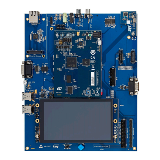
ST STM32MP157 Series User Manual (55 pages)
Brand:
ST
| Category:
Motherboard
| Size: 15 MB
Table of Contents
Figure 1. Stm32Mp157X-EV1 Top View
1
Figure 2. Stm32Mp157X-EV1 Bottom View
1
1 Features
2
2 Development Environment
3
System Requirements
3
Development Toolchains
3
Demonstration Software
3
3 Ordering Information
4
STM32MP157 Eval Board Products
4
Product Marking
4
Codification
4
Table 1. List of Available Products
4
Table 2. Codification Explanation
4
4 Conventions
5
Table 3. ON/OFF Convention
5
5 Delivery Recommendations
6
6 Hardware Layout and Configuration
7
Figure 3. Stm32Mp157X-EV1 Hardware Block Diagram
8
Figure 4. Stm32Mp157X-EV1 Board Overview
9
Table 4. Stm32Mp157X-EV1 Overview
10
Table 5. MB1263 Daughterboard Overview
10
Table 6. MB1262 Mother Board Overview
10
Power Supply Management
11
5 V Power Supply
11
Platform Power Tree
11
Figure 5. 5 V Power Supply Connector: MB1263/CN1
11
Stpmic
12
Figure 6. Stm32Mp157X-Ev1Platform Power Tree
12
Clocks
13
LSE Clock
13
HSE Clock
13
Physical Input Devices: Buttons
13
Reset Sources
13
Table 7. HW Configuration for the User Buttons and Leds
13
Table 8. Physical User Devices: Buttons
13
User Buttons and Leds
13
Boot Options
14
Table 9. HW Configuration for the BOOT Mode MB1263/SW1
14
Embedded ST-LINK/V2-1
15
Figure 7. Stm32Mp157X-EV1 Boot Related Switch Configuration
15
Drivers
16
Figure 8. STLINK USB Μb Connector Pinout MB1263/CN4
16
Table 10. STLINK USB Μb Connector Pinout MB1263/CN4
16
ST-LINK/V2-1 Firmware Upgrade
17
ETM TRACE Micto-38 Connector
17
Figure 9. USB Composite Device
17
Table 11. HW Configuration for the TRACE Connector MB1262/U10
17
Figure 10. TRACE Mictor-38 Connector: MB1262/U10
19
JTAG Connector
19
Table 12. TRACE MICTOR-38 Connector Pinout: MB1262/U10
19
Ddr3L
20
Emmc
20
Emmc IO Interface
20
NAND Flash
20
NAND IO Interface
20
Table 13. MB1262/CN14 JTAG Connector Pinout
20
Table 14. HW Configuration for the Quad-SPI Interface
20
Quad-SPI nor Flash
21
Quad-SPI IO Interface
21
Table 15. HW Configuration for the Quad-SPI Interface
21
Table 16. HW Configuration for the Quad-SPI Interface
21
Microsd Card
22
SD Card Interface
22
Table 17. IO Configuration for the SDIO Interface
22
Figure 11. SDCARD Connector Pinout MB1263/CN9
22
Audio
23
Audio Codec Interface
23
Table 18. SDCARD Connector Pinout MB1263/CN9
23
Table 19. IO Configuration for the Audio Codec Interface
23
Digital Microphones
24
Analog Microphone and Audio Jack Headphone
24
Table 20. HW Configuration for the Digital Microphones
24
Table 21. Audio Jack Connector Pinout MB1262/CN5
24
Figure 12. Audio Jack Connector MB1262/CN5
24
Audio Speaker out
25
SPDIF Input and Output
25
Table 22. Audio Jack Connector Pinout MB1262/CN4
25
Figure 13. Audio Jack Connector MB1262/CN4
25
IO Restriction to Other Features
26
Dsi Lcd
26
DSI LCD Interface
26
Table 23. IO Configuration for the LCD Interface
26
Figure 14. SPDIF Input MB1262/CN1 and Output MB1262/CN2 Connectors
26
Camera
27
Camera Interface
27
Table 24. IO Configuration for the Camera Interface
27
Gbps Ethernet
28
RGMII Interface
28
Table 25. IO Configuration for the Ethernet Interface
28
Usb Otg Hs
29
USB OTG Interface
29
Table 26. Ethernet Connector Pinout MB1262/CN3
29
Table 27. IO Configuration for the USB OTG Interface
29
Figure 15. Ethernet Connector MB1262/CN3
29
USB Host
30
USB Host Interface
30
Table 28. USB OTG Type Micro-AB Connector Pinout MB1262/CN16
30
Table 29. IO Configuration for the USB Host Interface
30
Figure 16. USB OTG Type Micro-AB Connector MB1262/CN16
30
RS-232 Port
31
Figure 17. Dual USB TYPE a Connector MB1262/CN18 and CN20
31
Table 30. USB Host Connector Pinout MB1262/CN18
31
Table 31. USB Host Connector Pinout MB1262/CN20
31
Figure 18. HW Configuration for the RS-232 Interface
32
Figure 19. RS-232 Connector Pinout MB1262/CN12
32
RS-232 Interface
32
Table 32. HW Configuration for the RS-232 Interface
32
Table 33. RS-232 Connector Pinout MB1262/CN12
32
IO Restriction to Other Features
33
Fdcan
33
Operating Voltage
33
FDCAN Interface
33
Table 34. IO Configuration for the SDIO Interface
33
Table 35. FDCAN Interface and Connector Pinout CN17
33
Figure 20. FDCAN Connector Pinout CN15
33
Smartcard
34
Smartcard Interface
34
Table 36. HW Configuration for the Smartcard Interface
34
Table 37. Smartcard Interface MB1262/U5 and Connector Pinout MB1262/CN23
34
Figure 21. Smartcard Connector Pinout MB1262/CN23
34
Adc/Dac
35
ADC/DAC IO Interface
35
2X Fast ADC
35
1X Slow ADC
35
Figure 22 ADC/DAC Connectors MB1263/JP7, JP8, JP9, JP10, and JP11
35
Limitations
36
I2C_EXT Connector
36
I2C_EXT IO Interface
36
Table 38. ADC/DAC Connectors JP7/JP8/JP9/JP10/JP11 Pinout
36
Table 39. HW Configuration for the I2C_EXT Interface
36
Figure 23. I2C_EXT Connector Pinout MB1262/CN13
36
Mfx Mcu
37
MFX IO Expander
37
Table 40. I2C_EXT Connector Pinout MB1262/CN13
37
Table 41. HW Configuration for the MFX Interface
37
Table 42. IO Signals Driven by the MFX
37
Motor Control
38
Motor Control IO Interface
38
Table 43. Motor Control Terminal and IO Function Assignment
38
Limitations
39
Figure 24. Motor Control Connector MB1262/CN22
39
Figure 25. MB1262/CN21 Connector
39
GPIO 40-Pin Expansion Connector
39
Table 44. MB1262/CN21 Connector Pinout
40
Table 45. HW Configurations to Enable SAI2 on the GPIO Connector
40
RGB LTDC Connector
41
Figure 26. MB1262/CN11 Connector
41
Table 46. MB1262/CN21 Connector Pinout
41
Limitations
42
A Appendix A Stm32Mp157X-EV1 Jumper Summary
43
Figure 27. Jumper Default Setting of the Stm32Mp157X-EV1
43
B Appendix B Stm32Mp157X-EV1 IO Assignment
44
Table 47. Stm32Mp157X-EV1 IO Assignment
44
Revision History
49
Table 48. Document Revision History
49
Table of Contents
50
Contents
50
List of Tables
53
List of Figures
54
Advertisement
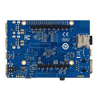
ST STM32MP157 Series User Manual (47 pages)
Discovery kits with increased-frequency 800 MHz STM32MP157 MPUs
Brand:
ST
| Category:
Computer Hardware
| Size: 13 MB
Table of Contents
Figure 1. STM32MP157F-DK2 Top View
1
Figure 2. STM32MP157F-DK2 Bottom View
1
Features
2
Ordering Information
3
Codification
3
Table 1. List of Available Products
3
Table 2. Codification Explanation
3
Development Environment
4
System Requirements
4
Development Toolchains
4
Demonstration Software
4
Conventions
5
Table 3. ON/OFF Convention
5
Delivery Recommendations
6
Hardware Layout and Configuration
7
Figure 3. Stm32Mp157X-Dkx Hardware Block Diagram
7
Figure 4. Stm32Mp157X-Dkx PCB Layout: Top Side
8
Embedded ST-LINK/V2-1
9
Description
9
Figure 5. Stm32Mp157X-Dkx PCB Layout: Bottom Side
9
Figure 6. CN11 ST-LINK USB Micro-B Connector Pinout
9
Drivers
10
ST-LINK/V2-1 Firmware Upgrade
10
Power Supply
10
STPMIC1 Power Supply
10
Table 4. CN11 ST-LINK USB Micro-B Connector Pinout
10
Clock Sources
11
LSE Clock References
11
HSE Clock References
11
Reset Sources
11
Boot Mode
11
Description
11
Table 5. Boot Mode Pins
11
Audio
12
Description
12
Operating Voltage
12
Audio Codec Interface
12
Table 6. I/O Configuration for the Audio Interface
12
Figure 7. Boot-Mode Switch SW1
12
Headphone Outputs
13
Audio Jack Connector
13
I/O Restriction
13
Table 7. CN10 Audio Jack Connector Pinout
13
Figure 8. CN10 Audio Jack Connector Pinout
13
USB Host
14
Description
14
USB Host Interface
14
Table 8. I/O Configuration for the USB Host Interface
14
Table 9. CN1 and CN5 USB Host Connector Pinout
14
Figure 9. CN1 and CN5 USB Type-A Connector Pinout
14
USB Type-C ® HS
15
Description
15
Operating Voltage
15
USB HS Source
15
USB Type-C ® Connector
15
Figure 10. CN7 USB Type-C ® Connector Pinout
15
Microsd ™ Card
16
Description
16
Operating Voltage
16
Microsd ™ Card Interface
16
Table 10. CN7 USB Type-C
16
Table 11. I/O Configuration for the SDIO Interface
16
Leds
17
Description
17
Table 12. CN15 Microsd
17
Figure 11. Microsd ™ Card Connector CN15
17
Operating Voltage
18
LED Interface
18
Buttons
18
Description
18
I/O Interface
18
Hdmi
18
Table 13. I/O Configuration of the LED Interfaces
18
Table 14. I/O Configuration for the Physical User Interface
18
HDMI ® I/O Interface
19
Table 15. I/O Configuration for the HDMI
19
Table 16. CN9 HDMI
20
Figure 12. CN9 HDMI ® Connector Pinout
20
Wi-Fi ® and Bluetooth ® Low Energy
21
Description
21
Operating Voltage
21
Wi-Fi ® I/O Interface
21
Bluetooth ® Low Energy I/O Interface
21
Table 17. I/O Configuration for the Wi-Fi
21
Table 18. I/O Configuration for the Bluetooth
21
Mipi Dsi Sm Lcd
22
Description
22
Operating Voltage
22
Figure 13. LCD Connection to MB1407
22
LCD Interface
23
Table 19. I/O Configuration of the LCD and CTP Interfaces
23
Figure 14. CN4 LCD Connector Pinout
23
Gigabit Ethernet
24
Description
24
Operating Voltage
24
Table 20. LCD Interface and CN4 Connector Pinout
24
Ethernet Interface
25
Table 21. I/O Configuration of the Ethernet Interface
25
Figure 15. CN8 Ethernet Connector Pinout
25
ARDUINO ® Connectors
26
Description
26
Operating Voltage
26
Table 22. CN8 Ethernet Connector Pinout
26
ARDUINO ® Interface
27
Table 23. I/O Configuration of the ARDUINO
27
Figure 16. ARDUINO ® Connectors Pinout
27
Table 24. Pinout of the ARDUINO
28
GPIO Expansion Connectors
29
Description
29
GPIO Expansion Connector Interface
30
Table 25. GPIO Connectors Pinout
30
Figure 17. GPIO Connectors
30
VBAT Connector
31
Description
31
Figure 18. CN3 VBAT Connector
31
Stm32Mp157X-Dkx Discovery Kits Information
32
Product Marking
32
STM32MP157D-DK1 Product History
32
Product Identification DK32MP157D1$AU1
32
STM32MP157F-DK2 Product History
32
Product Identification DK32MP157F2$AU1
32
Board Revision History
32
Board MB1272 Revision C-02
32
Board MB1407 Revision C-01
33
Stm32Mp157X-Dkx I/O Assignment
34
Table 26. Discovery Kit I/O Assignment
34
Federal Communications Commission (FCC) and ISED Canada Compliance
38
Statements
38
Additional FCC and ISED Canada Compliance Statements for STM32MP157F-DK2
38
CE Conformity
40
Warning
40
Simplified Declaration of Conformity
40
Revision History
41
Table 27. Document Revision History
41
Table of Contents
42
List of Tables
45
List of Figures
46
Advertisement
Related Products
ST STM32MP157A-EV1
ST STM32MP157C-EV1
ST STM32MP157F-EV1
ST STM32MP157D-EV1
ST STM32MP157x-EV1
ST STM32MP257F-EV1
ST STM32-MICRIUM
ST STM3210B-EVAL
ST STM32F334
ST STM320518-EVAL
ST Categories
Motherboard
Computer Hardware
Microcontrollers
Control Unit
Controller
More ST Manuals
Login
Sign In
OR
Sign in with Facebook
Sign in with Google
Upload manual
Upload from disk
Upload from URL