Table of Contents
Advertisement
Quick Links
UM1907
User manual
Discovery kit for STM32F7 Series with STM32F746NG MCU
Introduction
The STM32F746G-DISCO discovery board (32F746GDISCOVERY) is a complete
®
®
demonstration and development platform for STMicroelectronics ARM
Cortex
-M7 core-
2
based STM32F746NGH6 microcontroller. This microcontroller features four I
Cs, six SPIs
2
with three multiplexed simplex I
S, SDMMC, four USARTs, four UARTs, two CANs, three
12-bit ADCs, two 12-bit DACs, two SAIs, 8- to 14-bit digital camera module interface,
internal 320+16+4-Kbyte SRAM and 1-Mbyte Flash memory, USB HS OTG, USB FS OTG,
Ethernet MAC, FMC interface, Quad-SPI interface, SWD debugging support. This discovery
board offers everything required for users to get started quickly and develop applications
easily.
The full range of hardware features on the board helps users to evaluate almost all
™
peripherals (USB OTG HS, USB OTG FS, 10/100-Mbit Ethernet, microSD
card, USART,
SAI Audio DAC stereo with audio jack input and output, MEMS digital microphones,
SDRAM, Quad-SPI Flash memory, 4.3-inch color LCD-TFT with a capacitive multi-touch
™
panel, SPDIF RCA input, etc.) and to develop their applications. Arduino
Uno V3
connectors make it possible to easily connect extension shields or a daughterboard for
users' specific applications. The integrated ST-LINK/V2-1 provides an embedded in-circuit
debugger and programmer for the STM32.
The STM32F746G-DISCO board comes with the STM32 comprehensive software HAL
library together with various packaged software examples, as well as a direct access
®
™
to ARM
mbed
online resources at http://mbed.org.
Figure 1. STM32F746G-DISCO board (top view)
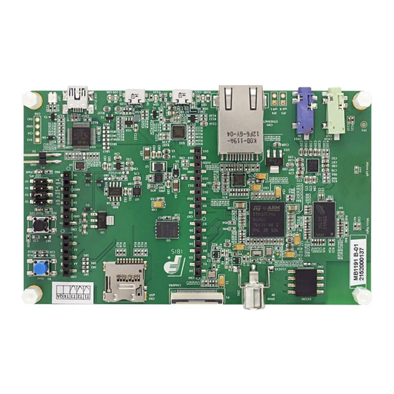
Figure 2. STM32F746G-DISCO board (bottom view)
1. Pictures not contractual.
March 2016
DocID027942 Rev 3
1/49
www.st.com
1
Advertisement
Table of Contents

Related Manuals for ST STM32F746G-DISCO


Summary of Contents for ST STM32F746G-DISCO
-
Page 1: Figure 1. Stm32F746G-Disco Board (Top View)
The integrated ST-LINK/V2-1 provides an embedded in-circuit debugger and programmer for the STM32. The STM32F746G-DISCO board comes with the STM32 comprehensive software HAL library together with various packaged software examples, as well as a direct access ®... -
Page 2: Table Of Contents
Embedded ST-LINK/V2-1 ........11... - Page 3 Electrical schematics ........26 Appendix A STM32F746G-DISCO IO assignment ......39 Appendix B Mechanical drawing.
- Page 4 STM32F746G-DISCO IO assignment ........
- Page 5 STM32F746G-DISCO board (bottom view) ........
-
Page 6: Features
Features UM1907 Features • STM32F746NGH6 microcontroller featuring 1 Mbyte of Flash memory and 340 Kbytes of RAM, in BGA216 package • On-board ST-LINK/V2-1 supporting USB reenumeration capability ® ™ mbed -enabled (see http://mbed.org) • • USB functions: virtual COM port, mass storage, debug port •... -
Page 7: Product Marking
Any consequences deriving from such usage will not be at ST charge. In no event, ST will be liable for any customer usage of these engineering sample tools as reference design or in production. -
Page 8: Hardware Layout And Configuration
Hardware layout and configuration UM1907 Hardware layout and configuration STM32F746G-DISCO discovery board is designed around the STM32F746NGH6 (216-pin TFBGA package). The hardware block diagram (see Figure 3) illustrates the connection between STM32F746NGH6 and peripherals (SDRAM, Quad-SPI Flash memory, camera module, color LCD, USB OTG connectors, USART, Ethernet, Audio, SPDIFRX, microSD... -
Page 9: Figure 4. Stm32F746G-Disco Discovery Board Top Layout
UM1907 Hardware layout and configuration Figure 4. STM32F746G-DISCO discovery board top layout DocID027942 Rev 3 9/49... -
Page 10: Figure 5. Stm32F746G-Disco Discovery Board Bottom Layout
Hardware layout and configuration UM1907 Figure 5. STM32F746G-DISCO discovery board bottom layout 10/49 DocID027942 Rev 3... -
Page 11: Embedded St-Link/V2-1
STM32 User manual (UM1075). 6.1.1 Drivers The ST-LINK/V2-1 requires a dedicated USB driver, which, for Windows XP, 7 and 8, can be found at www.st.com. In case the STM32F746G-DISCO discovery board is connected to the PC before the driver is installed, some STM32F746G-DISCO interfaces may be declared as “unknown” in the PC device manager. -
Page 12: St-Link/V2-1 Firmware Upgrade
The ST-LINK/V2-1 embeds a firmware upgrade mechanism for in-situ upgrade through the USB port. As the firmware may evolve during the life time of the ST-LINK/V2-1 product (for example new functionality, bug fixes, support for new microcontroller families), it is recommended to visit www.st.com... -
Page 13: Figure 9. Jp1 (5V Link)
The LED LD2 is lit when the STM32F746G-DISCO discovery board is powered by the 5V correctly. Caution: Do not connect the PC to the ST-LINK (CN14) when R109 is soldered. The PC may be damaged or the board not powered correctly. DocID027942 Rev 3... -
Page 14: Programming/Debugging When The Power Supply Is Not From
Connect the external power source to JP2 or CN6 or CN12 or CN13 Check the red LED LD2 is turned ON Connect the PC to USB connector CN14 If this order is not respected, the board may be powered by VBUS first from ST-LINK, and the following risks may be encountered: 14/49... -
Page 15: Clock Sources
X2, 25 MHz oscillator for the STM32F746NGH6 microcontroller and Ethernet PHY • X3, 32 KHz crystal for the STM32F746NGH6 embedded RTC Reset sources The reset signal of STM32F746G-DISCO discovery board is active low and the reset sources include: • Reset button B2 •... -
Page 16: Usb Otg Fs
• Power switch (U6) is ON and STM32F746G-DISCO works as an USB host • VBUS is powered by another USB host when STM32F746G-DISCO works as an USB device. The red LED LD6 will be lit when an overcurrent occurs. Note: STM32F746G-DISCO board should be powered by an external power supply when using OTG function. -
Page 17: Ethernet
Hardware layout and configuration 6.10 Ethernet The STM32F746G-DISCO discovery board supports 10/100-Mbit Ethernet communication by a PHY LAN8742A-CZ-TR (U9) from MICROCHIP and RJ45 jack (CN9). Ethernet PHY is connected to STM32F746NGH6 via RMII interface. 25 MHz clock for the PHY is generated by the oscillator X2, the 50 MHz clock for the STM32F746NGH6 is generated by the PHY RMII_REF_CLK. -
Page 18: Camera Module
UM1907 6.13 Camera module A connector P1 with the DCMI signals is available to connect a camera module such as STM32F4DIS-CAM (ST order code). 6.14 Display LCD-TFT The color display from ROCKTECH, 4.3-inch 480x272 LCD-TFT with capacitive touch panel is connected to RGB LCD interface of the STM32F746NGH6. -
Page 19: Connectors
UM1907 Connectors Connectors C extension connector CN2 Figure 13. I C extension connector CN2 (front view) Table 1. I C extension connector CN2 Pin number Description Pin number Description I2C_SDA (PB9) +3V3 I2C_SCL (PB8) RESET(PC10) NC or 5V Camera module connector P1 Figure 14. -
Page 20: Arduino Uno V3 Connectors
Arduino Uno V3 connectors CN4, CN5, CN6 and CN7 are female connectors compatible with Arduino standard. Most shields designed for Arduino can fit to the STM32F746G-DISCO discovery board. The Arduino connectors on STM32F746G-DISCO discovery board support the Arduino Uno Caution: The IOs of STM32 microcontroller are 3.3 V compatible instead of 5 V for Arduino Uno. -
Page 21: Table 3. Arduino Connectors (Cn4, Cn5, Cn6, Cn7)
UM1907 Connectors Table 3. Arduino connectors (CN4, CN5, CN6, CN7) Left connectors Right connectors CN No. Function Function CN No. Name Name I2C1_SCL I2C1_SDA AVDD AREF Ground SPI2_SCK IOREF 3.3V Ref SPI2_MISO PB14 digital TIM12_CH2, RESET NRST RESET PB15 SPI2_MOSI 3.3V TIM5_CH4, +3V3... -
Page 22: Usb Otg Hs Micro-Ab Connector Cn12
Connectors UM1907 USB OTG HS micro-AB connector CN12 Figure 15. USB OTG micro-AB connector CN12 (front view) Table 4. USB OTG HS micro-AB CN12 Pin number Description Pin number Description VBUS Ethernet RJ45 connector CN9 Figure 16. Ethernet RJ45 connector CN9 (front view) 22/49 DocID027942 Rev 3... -
Page 23: Usb Otg Fs Micro-Ab Connector Cn13
UM1907 Connectors Table 5. RJ45 connector CN9 Pin number Description Pin number Description A, yellow LED K, yellow LED CT, 3V3 K, green LED CT, 3V3 A, green LED USB OTG FS micro-AB connector CN13 Figure 17. USB OTG micro-AB connector CN13 (front view) Table 6. -
Page 24: Microsd Connector Cn3
SDMMC_CK (PC12) MicroSDcard_detect (PC13) ST-LINK/V2-1 USB type B connector CN14 The USB connector CN21 is used to connect the embedded ST-LINK/V2-1 to the PC for programming and debugging of the STM32F746NGH6 microncontroller. Figure 19. USB type B connector CN14 (front view) -
Page 25: Audio Stereo Speakers Jp3 And Jp4
UM1907 Connectors Table 8. USB type B connector CN14 Pin number Description Pin number Description VBUS (power) 5, 6 Shield Audio stereo speakers JP3 and JP4 The stereo audio outputs JP3 and JP4 are available to support stereo speakers (left and right). -
Page 26: Electrical Schematics
FMC_BA0 ULPI_STP uSD_D2 FMC_BA0 ULPI_NXT uSD_D3 FMC_BA1 ULPI_NXT uSD_D3 FMC_BA1 ULPI_CK uSD_Detect FMC_NBL0 ULPI_CK uSD_Detect FMC_NBL0 ULPI_D[0..7] FMC_NBL1 Title: STM32F746 Discovery Interconnexion ULPI_D[0..7] FMC_NBL1 FMC_SDNE0 SDRAM FMC_SDNE0 Project: STM32F746G-DISCO FMC_SDCKE0 SDRAM FMC_SDCKE0 Size: Reference: MB1191 Revision: B-04 Date: 10/16/2015 Sheet:... -
Page 27: Figure 21. St-Link/V2-1 With Support Of Swd Only
Figure 21. ST-LINK/V2-1 with support of SWD only T_JTCK SB14 PA14 SWCLK R112 R108 SB17 PA13 T_JTMS SWDIO 4K7_1%_0402 BAT60JFILM SB15 T_NRST 2K7_1%_0402 NRST SB16 T_SWO R101 R105 R109 10K_1%_0402 100K_1%_0402 3V3_ST_LINK Board Ident: PC13=0 R100 SWCLK SWDIO Not Fitted... -
Page 28: Figure 22. Joystick, Leds And Pushbutton
USER & WAKE-UP Button uSD_D0 uSD_D1 uSD_D2 B_USER uSD_D3 B_USER uSD_CLK uSD_CMD 100nF PJS008-2003 SMS064FF or SMS128FF [NA] uSD_Detect 0_5%_0402 Input pin with pull-up Title: Joystick, ACP, LEDs and Push Button Project: STM32F746G-DISCO Size: Reference: MB1191 Revision: B-04 Date: 10/16/2015 Sheet:... -
Page 29: Figure 23. Audio Codec Cirrus And Connectors
RCA in Yellow for SPDIF input [NA] Very close to Output pin 4 TP_PH15 TP_PH15 of first stage SPDIF_RX0 22nF 22nF 74LVC1G04SE 74LVC1G04SE Title: Audio Codec WOLFSON and connectors RCA_SMD Project: STM32F746G-DISCO 100nF 100nF Size: Reference: MB1191 Revision: B-04 Date: 10/16/2015 Sheet:... -
Page 30: Figure 24. Quad-Spi Flash Memory (Micron)
Quad SPI Flash Memory 10K_1%_0402 QSPI_NCS QSPI_NCS QSPI_CLK QSPI_CLK QSPI_D0 QSPI_D0 100nF_X7R_10%_0402 QSPI_D1 QSPI_D1 QSPI_D2 QSPI_D2 DQ2/Vpp/W# DQ2/Vpp/W# QSPI_D3 QSPI_D3 DQ3/HOLD# DQ3/HOLD# N25Q128A13EF840E (MICRON) Title: Quad SPI Flash Memory (MICRON) Project: STM32F746G-DISCO Size: Reference: MB1191 Revision: B-04 Date: 10/16/2015 Sheet:... -
Page 31: Figure 25. Arduino Uno Connectors
PWM/CS/D5 ADC3_IN7 ARD_A2 ARD_D4 ADC3_IN6 ARD_A3 ARD_D3 TIM3_CH1 PWM/D3 ARD_D2 ADC3_IN5 ARD_A4 ARD_D1 USART6_TX TX/D1 ARD_D0 USART6_RX RX/D0 SDA/D14 ARD_D14 F201-1*06MGF-W1-BA F201-1*08MGF-W1-BA ADC3_IN4 ARD_A5 SCL/D15 ARD_D15 Title: Arduino UNO connectors Project: STM32F746G-DISCO Size: Reference: MB1191 Revision: B-04 Date: 10/16/2015 Sheet:... -
Page 32: Figure 26. Sdram (Micron)
VDDQ VSSQ 100nF_X7R_10%_0402 VDDQ VSSQ 100nF_X7R_10%_0402 VDDQ VSSQ 100nF_X7R_10%_0402 VDDQ VSSQ 100nF_X7R_10%_0402 VDDQ VSSQ 100nF_X7R_10%_0402 VDDQ VSSQ 100nF_X7R_10%_0402 100nF_X7R_10%_0402 100nF_X7R_10%_0402 100nF_X7R_10%_0402 100nF_X7R_10%_0402 MT48LC4M32B2B5-6A (MICRON) Place close SDRAM Title: SDRAM (MICRON) Project: STM32F746G-DISCO Size: Reference: MB1191 Revision: B-04 Date: 10/16/2015 Sheet:... -
Page 33: Figure 27. Usb Otg Fs With Micro A-B Connector
USB_FS1_N OTG_FS_N R125 USB_FS1_P OTG_FS_P R133 OTG_FS_ID R136 330_1%_0603 Vbus D+out D+in D-out D-in LED, green R134 47K_1%_0402 EMIF02-USB03F2 9013-SOT23 R135 100K Title: USB OTG FS with Micro A-B connector Project: STM32F746G-DISCO Size: Reference: MB1191 Revision: B-04 Date: 10/16/2015 Sheet:... -
Page 34: Figure 28. Stm32F746Ngh6 Connection
VDDA VSSA VREF+ VREF+ VREF- VBAT VCAP1 100nF BYPASS-REG VCAP2 100nF 100nF 100nF 100nF 100nF 100nF 100nF 100nF 100nF 100nF STM32F746NGH6 2.2uF 2.2uF Title: STM32F746NGH6 Connexion Project: STM32F746G-DISCO Size: Reference: MB1191 Revision: B-04 Ceramic capacitor (Low ESR) Date: 10/16/2015 Sheet:... -
Page 35: Figure 29. Usb Otg Hs Phy With Micro A-B Connector
100nF 100nF NRST RESETB GNDPAD USB3320C-EZK R104 R110 R113 0_5%_0402 0_5%_0402 0_5%_0402 REFSEL0 REFSEL1 REFSEL2 R103 R106 R111 Title: USB OTG HS PHY with Micro A-B connector [NA] [NA] [NA] Project: STM32F746G-DISCO Size: Reference: MB1191 Revision: B-04 Date: 10/16/2015 Sheet:... -
Page 36: Figure 30. Ethernet Phy With Rj45 Connector
VDD2A BLM18PG121SN1D NRST nRST VDDCR RMII_REF_CLK nINT/REFCLK0 CHS GND Shield XTAL2 Shield OSC_25M 100nF 100nF 10uF OSC_25M XTAL1/CLKIN GND_EP 470pF HR961160C LAN8742A-CZ-TR 100nF 10uF Title: Ethernet PHY with RJ45 connector Project: STM32F746G-DISCO Size: Reference: MB1191 Revision: B-04 Date: 10/16/2015 Sheet:... -
Page 37: Figure 31. External Camera Connector
DCMI_D5 DCMI_SDA DCMI_SCL DCMI_D6 DCMI_SCL DCMI_D7 OSC_24M OSC_24M DCMI_PIXCK DCMI_HSYNC DCMI_VSYNC OSC_24M Camera_CLK 100_1%_0402 10K_1%_0402 NZ2520SB-24.00M DCMI_PWR_EN DCMI_NRST DCMI_SDA 100_1%_0402 100nF DCMI_SCL 100_1%_0402 FPU330ZH-BT1D3-CA 10uF 100nF Title: External Camera connector Project: STM32F746G-DISCO Size: Reference: MB1191 Revision: B-04 Date: 10/16/2015 Sheet:... -
Page 38: Figure 32. 4.3-Inch Lcd With Capacitive Touch
LCD_B[0..7] LCD_B[0..7] LCD_R[0..7] LCD_R[0..7] LCD_BL_CTRL LCD_BL_CTRL LCD_CLK LCD_CLK LCD_HSYNC LCD_HSYNC LCD_VSYNC LCD_VSYNC LCD_DE LCD_DE LCD_DISP LCD_DISP LCD_INT LCD_INT LCD_RST LCD_RST LCD_SCL LCD_SCL LCD_SDA LCD_SDA Title: LCD 4.3" with Capacitive Touch Project: STM32F746G-DISCO Size: Reference: MB1191 Revision: B-04 Date: 10/16/2015 Sheet:... -
Page 39: Appendix A Stm32F746G-Disco Io Assignment
UM1907 STM32F746G-DISCO IO assignment Appendix A STM32F746G-DISCO IO assignment Table 10. STM32F746G-DISCO IO assignment Pin No. Pin Name Signal or Label Comment LTDC_B0 OTG_HS_OverCurrent QUADSPI_BK1_IO2 PG14 ETH_TXD1 FMC_NBL1 FMC_NBL0 ARDUINO SCL/D15 USB_OTG_HS_ULPI_D7 ARDUINO PWM/D3 SYS_JTDO-SWO SPDIF_RX0 PC12 SDMMC_CK PA15 ARDUINO PWM/D9... - Page 40 STM32F746G-DISCO IO assignment UM1907 Table 10. STM32F746G-DISCO IO assignment (continued) Pin No. Pin Name Signal or Label Comment SAI2_MCLK_A LTDC_DE LTDC_B7 LTDC_B6 PG12 LTDC_B4 PG10 SAI2_SD_B PJ14 LTDC_B2 OTG_FS_PowerSwitchOn DCMI_D5 FMC_D3_DA3 ARDUINO D7 ARDUINO D8 PA11 USB_OTG_FS_DM PC13 uSD_Detect FMC_A0...
- Page 41 UM1907 STM32F746G-DISCO IO assignment Table 10. STM32F746G-DISCO IO assignment (continued) Pin No. Pin Name Signal or Label Comment VCAP_2 Connected to C48 PH13 DCMI_PWR_EN PH14 DCMI_D4 ARDUINO PWM/CS/D10 VCP_TX PC15/OSC32_OUT RCC_OSC32_OUT PI11 B_USER LTDC_G6 LTDC_G7 SDMMC_D1 ARDUINO PWM/D5 PH0/OSC_IN RCC_OSC_IN...
- Page 42 STM32F746G-DISCO IO assignment UM1907 Table 10. STM32F746G-DISCO IO assignment (continued) Pin No. Pin Name Signal or Label Comment PH1/OSC_OUT RCC_OSC_OUT FMC_A3 PI14 LTDC_CLK USB_OTG_HS_ULPI_NXT LTDC_G1 PJ10 LTDC_G3 FMC_SDCLK ARDUINO TX/D1 NRST Hardware RESET FMC_A4 FMC_SDNWE FMC_SDNE0 LTDC_G0 LTDC_G2 ARDUINO D4...
- Page 43 UM1907 STM32F746G-DISCO IO assignment Table 10. STM32F746G-DISCO IO assignment (continued) Pin No. Pin Name Signal or Label Comment LTDC_R7 PD15 FMC_D1_DA1 PB13 USB_OTG_HS_ULPI_D6 PD10 FMC_D15_DA15 PF10 ARDUINO A1 ARDUINO A2 ARDUINO A3 FMC_SDCKE0 BYPASS_REG Connected to PD R20 VCAP_1 Connected to C47...
- Page 44 STM32F746G-DISCO IO assignment UM1907 Table 10. STM32F746G-DISCO IO assignment (continued) Pin No. Pin Name Signal or Label Comment ETH_REF_CLK PA0/WKUP ARDUINO A0 DCMI_HSYNC ETH_RXD0 PF13 FMC_A7 FMC_A10 LTDC_R4 FMC_D5_DA5 PD11 QUADSPI_BK1_IO0 FMC_A15_BA1 FMC_A14_BA0 I2C3_SCL DCMI_D0 PH11 DCMI_D2 VREF+ Connected to VDDA...
- Page 45 UM1907 STM32F746G-DISCO IO assignment Table 10. STM32F746G-DISCO IO assignment (continued) Pin No. Pin Name Signal or Label Comment LTDC_R2 FMC_D4_DA4 PE10 FMC_D7_DA7 1. By default OTG_FS_VBUS is driven by the software and not by the alternate function of the STM32F746NGH6 (R64 = ON, R63 = OFF, R58 = ON and PA9 = VCP_TX (Virtual Com Port) and PJ12 = OTG_FS_VBUS).
-
Page 46: Appendix B Mechanical Drawing
Mechanical drawing UM1907 Appendix B Mechanical drawing Figure 33. Mechanical drawing 46/49 DocID027942 Rev 3... -
Page 47: Appendix C Compliance Statements
UM1907 Compliance Statements Appendix C Compliance Statements Federal Communications Commission (FCC) and Industry Canada (IC) Compliance Statement C.1.1 FCC Compliance Statement Part 15.19 This device complies with Part 15 of the FCC Rules. Operation is subject to the following two conditions: (1) this device may not cause harmful interference, and (2) this device must accept any interference received, including interference that may cause undesired operation. -
Page 48: Revision History
Revision history UM1907 Revision history Table 11. Document revision history Date Revision Changes 12-Jun-2015 Initial release. Updated cover page adding mbed-enabled logo. Added: Section 1: Features Section 2: Demonstration software Section 3: Product marking Section 4: Ordering information 02-Nov-2015 Section 5: Technology partners Section Appendix C: Compliance Statements Updated Section 8: Electrical schematics... - Page 49 ST products and/or to this document at any time without notice. Purchasers should obtain the latest relevant information on ST products before placing orders. ST products are sold pursuant to ST’s terms and conditions of sale in place at the time of order acknowledgement.
Need help?
Do you have a question about the STM32F746G-DISCO and is the answer not in the manual?
Questions and answers