Sign In
Upload
Download
Table of Contents
Contents
Add to my manuals
Delete from my manuals
Share
URL of this page:
HTML Link:
Bookmark this page
Add
Manual will be automatically added to "My Manuals"
Print this page
×
Bookmark added
×
Added to my manuals
Manuals
Brands
Autonics Manuals
Controller
DPU Series
User manual
Autonics DPU Series User Manual
1-phase digital thyristor unit
Hide thumbs
Also See for DPU Series
:
Manual
(22 pages)
,
User manual
(61 pages)
1
2
3
4
5
6
7
8
Table Of Contents
9
10
11
12
13
14
15
16
17
18
19
20
21
22
23
24
25
26
27
28
29
30
31
32
33
34
35
36
37
38
39
40
41
42
43
44
45
46
47
48
49
50
51
52
53
54
55
page
of
55
Go
/
55
Contents
Table of Contents
Bookmarks
Table of Contents
Usermanualguide
Usermanualsymbols
Safetyprecautions
Table of Contents
Tableofcontents
1 Productintroduction
Features
Orderinginformation
Partdescriptions
2 Specifications
3 Dimensions
4 Connections
5 Installationandinitialoperation
Installation
Initialdisplay
Parameters
Monitoringmode
Operationmode[ OP ]
Settingmode1[ ST-1 ]
Setting Mode 2[ ST-2 ]
6 Parametersettingandfunctions
Controlinput
Functions
Controlmethod[ C-MD ]
Softstart[ ST-T ]
Startlimit[ S-LM ]Andstartlimittime[ S-LT ]
Outputslopesetting[ SLOP ]
Outputslopemanualadjustment[ A-GA ]
Base-Up[ B-UP ]
Slowup/Slowdown
Outputhighlimitvalue[ H-OL ],Outputlowlimitvalue[ L-OL ]
Digitalinput(DI)
Proportionalandintegralconstantsetoffeedbackcontrol
Inputcorrection[ IN-B ]
Inputslopecorrection[ SPAN ]
Displayvaluecontentselection[ DISP ]
Bargraphcontentselection[ BAR ]
Loadresistancedisplaymethod[ DRES ]
Fullloadautorecognition[ F-LD ]
Parameterlock[ LOCK ]
Alarm
Overcurrent Alarm [ OC-A ]
Current Limit [ C-LM ]
Overvoltagealarm[ OV-A ]
Fusedisconnectionalarm[ FUSE ]
Heatsinkoverheatingalarm[ HEAT ]
Elementerroralarm[ SCR ]
Heater Disconnection Alarm [ HB-A ]
7 Factorydefault
8 Maintenance
Fuse
Thyristor(Scr)
9 Modbusmappingtable
Functioncode3(0X03)=Readholdingresisters
Functioncode4(0×04)=Readinputresisters
Functioncode6(0×06)=Writesingleresisters
Functioncode16(0×10)=Writemultipleresisters
Addressmappingtable
Inputresisters
Holdingresisters
Advertisement
Quick Links
1
Usermanualguide
2
Connections
3
Parameters
4
Alarm
Download this manual
The invisible hand for more convenient world
sensors & controllers
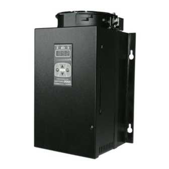
Digital Thyristor Unit
DPU(1-phase) Series
USER MANUAL
DPU Series
Thank you very much for selecting Autonics products.
For your Safety, please read the following before using.
Table of
Contents
Previous
Page
Next
Page
1
2
3
4
5
Advertisement
Table of Contents
Need help?
Do you have a question about the DPU Series and is the answer not in the manual?
Ask a question
Questions and answers
Subscribe to Our Youtube Channel
Related Manuals for Autonics DPU Series
Controller Autonics DPU Series User Manual
Power controllers (61 pages)
Controller Autonics DPU Series Manual
(22 pages)
Controller Autonics Digipower 2000 User Manual
1-phase digital thyristor unit (55 pages)
Controller Autonics DPU1 Series Manual
Digital power controllers (23 pages)
Controller Autonics DPU1 Series Product Manual
Single-phase / 3-phase digital power controllers (9 pages)
Controller Autonics TK series User Manual
High accuracy standard temperature controller (124 pages)
Controller Autonics TC4Y Manual
Tc series economical single display type, pid control (14 pages)
Controller Autonics SPR3-1 Series Instruction Manual
Led display slim power controller (2 pages)
Controller Autonics TC4S Manual
Tc series economical single display type, pid control (14 pages)
Controller Autonics TC4S Instruction Manual
Tc4 series (2 pages)
Controller Autonics SPR3 Series Product Manual
3-phase slim power controllers (5 pages)
Controller Autonics TZ4SP Instruction Manual
Tz series dual pid control temperature controller (2 pages)
Controller Autonics TZN4S Instruction Manual
Tzn series (2 pages)
Controller Autonics TZN Series Manual
Dual pid control temperature controller (17 pages)
Controller Autonics SPC1 Series Quick Start Manual
Single phase power controller (6 pages)
Controller Autonics PA10-U Instruction Manual
Pa10 series multifunctional sensor controller (2 pages)
This manual is also suitable for:
Digipower 2000
Table of Contents
Save PDF
Print
Rename the bookmark
Delete bookmark?
Delete from my manuals?
Login
Sign In
OR
Sign in with Facebook
Sign in with Google
Upload manual
Upload from disk
Upload from URL


Need help?
Do you have a question about the DPU Series and is the answer not in the manual?
Questions and answers