Autonics TK series User Manual
High accuracy standard temperature controller
Hide thumbs
Also See for TK series:
- Communications manual (38 pages) ,
- User manual (28 pages) ,
- User manual for communication (26 pages)
Table of Contents
Advertisement
Advertisement
Table of Contents

Subscribe to Our Youtube Channel
Related Manuals for Autonics TK series


Summary of Contents for Autonics TK series
- Page 1 1 Product Introduction USER MANUAL © Copyright Reserved Autonics Co., Ltd.
- Page 2 1 Product Introduction © Copyright Reserved Autonics Co., Ltd.
-
Page 3: Preface
1 Product Introduction Preface Thank you for purchasing an Autonics product. Please familiarize yourself with the information contained in the Safety Precautions section before using this product. This user manual contains information about the product and its proper use, and should be kept in a place where it will be easy to access. -
Page 4: User Manual Guide
The manual's content may vary depending on changes to the product's software and other unforeseen developments within Autonics, and is subject to change without prior notice. Upgrade notice is provided through out homepage. We contrived to describe this manual more easily and correctly. However, if there are any ... -
Page 5: User Manual Symbols
Failure to follow instructions can result in serious injury or death. Failure to follow instructions can lead to a minor injury or product damage. An example of the concerned feature's use. Annotation mark. ※1 © Copyright Reserved Autonics Co., Ltd. -
Page 6: Safety Precautions
Failure to follow this instruction may result in electric shock or fire. Do not use the unit where flammable or explosive gas, humidity, direct sunlight, radiant heat, vibration, or impact may be present. Failure to follow this instruction may result in fire or explosion. © Copyright Reserved Autonics Co., Ltd. - Page 7 Failure to follow this instruction may result in fire or explosion. For installing the unit with reinforced insulation, use the power supply unit which basic level is ensured. The above specifications are subject to change and some models may be discontinued without notice. © Copyright Reserved Autonics Co., Ltd.
- Page 8 1 Product Introduction © Copyright Reserved Autonics Co., Ltd.
-
Page 9: Table Of Contents
Input digital filter [PAR3 → MAvF] ............... 59 6.1.6 High/Low-limit value of setting value(SV) [PAR3 → H-SV/ L-SV] ..... 60 6.1.7 Control output ......................61 Control output mode [PAR3 → O-FT] ............61 6.2.1 © Copyright Reserved Autonics Co., Ltd. - Page 10 Password settings [PAR5 → PWD]............. 105 6.7.9 Setting group parameter description ............ 107 Setting group [ SV ] ....................107 MV monitoring/manual control setting group [ MV ] ..........107 Parameter 1 setting group [ PAR1 ]............... 108 © Copyright Reserved Autonics Co., Ltd.
- Page 11 Password entry parameter ..................116 Parameter change reset parameters ..............116 DAQMaster ....................117 Overview ....................... 117 Major features ....................... 118 Special feature for TK Series ................120 8.3.1 Parameter mask ..................120 8.3.2 User parameter group [PARU] ..............122...
- Page 12 1 Product Introduction © Copyright Reserved Autonics Co., Ltd.
-
Page 13: Product Introduction
Product Introduction Features TK Series – standard PID temperature controller – realizes more powerful control with super high-speed sampling cycles of 50 ms and ±0.3% display accuracy. It supports diverse control modes including heating & cooling simultaneous control, and automatic/manual control and communication functions. -
Page 14: Components And Accessories
(1) Components Make sure all of the above components are included with your product package before use. If a component is missing or damaged, please contact Autonics or your distributor. Visit www.autonics.com to download a copy of the user manual. - Page 15 (unit: mm) PG-11 PS-11(N) (unit: mm) (unit: mm) Communication converter SCM-WF48 (Wi-Fi to RS485·USB SCM-US48I wireless communication converter) (USB to RS485 converter) SCM-38I SCM-US (USB to Serial converter) (RS232C to RS485 converter) © Copyright Reserved Autonics Co., Ltd.
- Page 16 1 Product Introduction Current transformer(CT) CSTC-E80LN Max. load current: 80A (50/60Hz) ※Max. load current for TK4 Series is 50A. Current ratio: 1/1000 Wire wounded resistance: 31Ω ±10% (unit: mm) © Copyright Reserved Autonics Co., Ltd.
- Page 17 1 Product Introduction CSTC-E200LN Max. load current: 200A (50/60Hz) ※Max. load current for TK4 Series is 50A. Current ratio: 1/1000 Wire wounded resistance: 20Ω±10% (unit: mm) © Copyright Reserved Autonics Co., Ltd.
- Page 18 For using CT, do not supply first part current when opening CT output. It occurs high voltage at CT output part. Using current of above CTs are same as 50A. But be sure that inner hole sizes are different. Select it properly for the environment. © Copyright Reserved Autonics Co., Ltd.
- Page 19 DS/DA-T Series (RS485 communication input type display unit) Connect RS485 communication input type display unit (DS/DA-T Series) and TK Series, the display unit displays present value of the device without PC/PLC. Images of components and accessories may differ from actual products.
-
Page 20: Ordering Information
Current output or SSR drive output selectable None Standard ※Select in case of standard control (heating or cooling) ⑦ OUT2 Control Heating R Relay output ※ 3 Output & C Current output or SSR drive output selectable Cooling © Copyright Reserved Autonics Co., Ltd. - Page 21 ※9. 11Pin socket(PG-11, PS-11(N)): Sold separately CT (Current Transformer) input is supported by all models. However, TK4SP (11 pin plug type) does not support CT input due to its limited number of terminal blocks. © Copyright Reserved Autonics Co., Ltd.
-
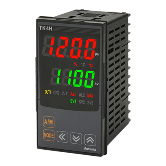
Page 22: Parts Descriptions
④ Multi SV indicator: One of SV1 to 3 indicator will be ON in case of selecting multi SV ⑤ function. Auto tuning indicator: It flashes by 1 sec. when executing auto tuning. ⑥ © Copyright Reserved Autonics Co., Ltd. - Page 23 DAQMaster installed in PC. Use this for connecting SCM-US(USB to Serial converter, sold separately). Input selection switch: Used when switching sensor (TC, RTD) input ↔ analog input(mV, ⑭ V, mA) (only the previous models) 7-Segment Display Characters © Copyright Reserved Autonics Co., Ltd.
- Page 24 1 Product Introduction © Copyright Reserved Autonics Co., Ltd.
-
Page 25: Specifications
ON/OFF, P, PI, PD, PID control mode type Heating or Cooling RTD/ Thermocouples: 1 to 100℃/℉ (0.1 to 100.0℃/℉) variable Hysteresis Analog: 1 to 100 digit Proportional band (P) 0.1 to 999.9℃/℉ (0.1 to 999.9%) © Copyright Reserved Autonics Co., Ltd. - Page 26 In case of TK4SP Series, ±1℃ will be added to the degree standard. ※2. The weight is with packaging and the weight in parentheses is only unit weight. ※Environment resistance is rated at no freezing or condensation. © Copyright Reserved Autonics Co., Ltd.
-
Page 27: Dimensions
3 Dimensions Dimensions (unit: mm) (1) TK4N Series (2) TK4S Series (3) TK4SP Series (4) TK4M Series © Copyright Reserved Autonics Co., Ltd. - Page 28 3 Dimensions (5) TK4H Series (6) TK4W Series (7) TK4L Series © Copyright Reserved Autonics Co., Ltd.
- Page 29 3 Dimensions (8) Bracket TK4N Series TK4S, TK4SP Series TK4M/W/H/L Series © Copyright Reserved Autonics Co., Ltd.
- Page 30 3 Dimensions (9) Terminal cover (sold separately) TK4N COVER (48×24mm) ※TK4N COVER is accessory. RSA-COVER (48×48mm) RMA-COVER (72×72mm) RHA-COVER (48×96mm, 96×48mm) © Copyright Reserved Autonics Co., Ltd.
- Page 31 TK4N TK4S/SP Other Series Insert the unit into a panel Insert the unit into a panel fasten the bracket by pushing with tools fasten the bolt with a (+) driver. with a (-) driver. © Copyright Reserved Autonics Co., Ltd.
- Page 32 3 Dimensions © Copyright Reserved Autonics Co., Ltd.
-
Page 33: Connections
OUT2 is usable as transmisstion output 2. (1) TK4N Series (2) TK4S Series Features one digital input terminal (DI-1) due to limited number of terminal blocks. Supports two multi SVs (SV1 and SV2) only. © Copyright Reserved Autonics Co., Ltd. - Page 34 SVs (SV1 and SV2) only. (5) TK4W, TK4H, TK4L Series ※ Digital input is not electrically insulated from internal circuits, so it sholud be insulated when connecting other circuits. (photocoupler, relay, independent switch) © Copyright Reserved Autonics Co., Ltd.
-
Page 35: Precautions For Wiring
Do not tie together with the AC power line and communication line. Only use twisted pair wires for the communication lines. Do not allow the communication line to exceed 800m in length. For further details, please refer to ‘6.6 Communication ’. © Copyright Reserved Autonics Co., Ltd. - Page 36 4 Connections © Copyright Reserved Autonics Co., Ltd.
-
Page 37: Preparation And Startup
Relay contact OUT1 SSR drive output control R, S, C (standard ON/OFF, cycle, phase control) output Current + SSR drive output None OUT2 control Relay contact N, R, C output Current + SSR drive output © Copyright Reserved Autonics Co., Ltd. -
Page 38: Basic Controls
③ Press the key to save the set value. If there is no additional ④ key operations in 3 sec., the changed SV is automatically saved. © Copyright Reserved Autonics Co., Ltd. -
Page 39: Mv Monitoring And Manual Control
MV monitoring stage, or any other stage, will revert the system to auto control mode. During heating & cooling control mode, pressing the key once from the MV ⑫ monitoring stage, or any other stage, will skip the system to the cooling MV monitoring stage. © Copyright Reserved Autonics Co., Ltd. - Page 40 Heating MV remains in effect during cooling monitoring and manual cooling control. When setting ditial input function as AUTO/MANUAL, MV monitoring and control status Control status Monitoring AUTO Not changed Avaliable MANUAL Changeable TK4N/S/SP model’s the key alternates the key. © Copyright Reserved Autonics Co., Ltd.
-
Page 41: Parameter Group
5 Preparation and Startup Parameter group © Copyright Reserved Autonics Co., Ltd. - Page 42 5 Preparation and Startup © Copyright Reserved Autonics Co., Ltd.
- Page 43 If password is not valid, the screen will be shifted to password code required window. Press any key among to return to password entering window. Press key to return to RUN mode. In case you forget password, contact Autonics after checking password code. ※2. TK4N/4S/4SP do not have key. The key replaces key.
-
Page 44: Parameter Groups
5 Preparation and Startup Parameter groups 5.4.1 Parameter 1 group [PAR1] © Copyright Reserved Autonics Co., Ltd. -
Page 45: Parameter 2 Group [Par2]
5 Preparation and Startup 5.4.2 Parameter 2 group [PAR2] © Copyright Reserved Autonics Co., Ltd. - Page 46 5 Preparation and Startup © Copyright Reserved Autonics Co., Ltd.
-
Page 47: Parameter 3 Group [Par3]
5 Preparation and Startup 5.4.3 Parameter 3 group [PAR3] © Copyright Reserved Autonics Co., Ltd. - Page 48 + SSR drive output - OUT1 O!MA are not displayed. - O!SR can set to STND CYCL PHAS -When O@SR is set to SSR it is held in STND and parameter is not displayed. © Copyright Reserved Autonics Co., Ltd.
-
Page 49: Parameter 4 Group [Par4]
5 Preparation and Startup 5.4.4 Parameter 4 group [PAR4] © Copyright Reserved Autonics Co., Ltd. - Page 50 5 Preparation and Startup © Copyright Reserved Autonics Co., Ltd.
- Page 51 5 Preparation and Startup © Copyright Reserved Autonics Co., Ltd.
-
Page 52: Parameter 5 Group [Par5]
5 Preparation and Startup 5.4.5 Parameter 5 group [PAR5] © Copyright Reserved Autonics Co., Ltd. - Page 53 5 Preparation and Startup © Copyright Reserved Autonics Co., Ltd.
- Page 54 5 Preparation and Startup © Copyright Reserved Autonics Co., Ltd.
-
Page 55: Parameter Settings And Functions
-199.9 to 650.0 -199.9 to 999.9 JPt 100Ω JPtL -199.9 to 600.0 -199.9 to 999.9 DPt 50Ω DPt5 -200 to 650 -328 to 1202 DPt 100Ω DPtH DPt 100Ω -199.9 to 650.0 -199.9 to 999.9 DPtL © Copyright Reserved Autonics Co., Ltd. -
Page 56: Input Type [Par3 → In-T]
When selecting the input temperature sensor, you can set the desired units (℃, ℉) of temperature/scale value to be displayed. Setting Factory Parameter Setting range Unit group default ?C / ?F PAR3 UNIT This parameter will not be displayed if analog input has been selected. © Copyright Reserved Autonics Co., Ltd. -
Page 57: Analog Input/Scale Value
You can set high limit input values for actual use within the analog input range. Setting Factory Parameter Setting range Unit group default Low-limit input value [L-RG] + F.S. 10% to PAR3 H-RG 1)00 maximum temperature range © Copyright Reserved Autonics Co., Ltd. - Page 58 Sets the display unit to ℉ and turns on the ℉ of front unit indicator. Sets the display unit to % and turns on the % of front unit indicator. Sets the display unit to an undefined unit. The LED unit indicator will not turn on. © Copyright Reserved Autonics Co., Ltd.
-
Page 59: Input Correction [Par3 → In-B]
If the input digital filter is set to 0.4 sec., digital filtering is applied to a sampling value collected over 0.4 sec. (400 ms). When the input digital filter is used, present value (PV) can vary from the actual input value. © Copyright Reserved Autonics Co., Ltd. -
Page 60: High/Low-Limit Value Of Setting Value(Sv) [Par3 → H-Sv/ L-Sv]
Attempts to set the limits outside the min/max input range, or analog's high/low-limits, are not accepted. Instead, the previous settings are retained. Set value(SV) can only be set within the SV low-limit [L-SV] and SV high-limit [H-SV] range. SV lower-limit [L-SV] cannot exceed SV high-limit [H-SV]. © Copyright Reserved Autonics Co., Ltd. -
Page 61: Control Output
Heating/cooling output can be selected among Relay output, SSR drive output and current output depending on model types choosen according to your application environment. (Note that SSR drive output of OUT2 operates standard control.) © Copyright Reserved Autonics Co., Ltd. - Page 62 -199.9 (overlap band) to 000.0 (not used) to 999.9 (dead band) (temperature L) Set range (analog): -99.9 (overlap band) to 000.0 (not used) to 099.9 (dead band) Factory default: 0000 (temperature H), 000.0 (temperature L, analog), (unit: temperature ℃/℉, analog % F.S.) © Copyright Reserved Autonics Co., Ltd.
- Page 63 6 Parameter Settings and Functions (1) Using a Deadband © Copyright Reserved Autonics Co., Ltd.
- Page 64 6 Parameter Settings and Functions (2) Using an Overlap Band © Copyright Reserved Autonics Co., Ltd.
- Page 65 6 Parameter Settings and Functions (3) Using neither a Dead band nor an Overlap Band Depends on the set value of the heating integration time[H-I], cooling integration time[C-I], actual operation may be different. © Copyright Reserved Autonics Co., Ltd.
-
Page 66: Mv High/Low-Limit Value Settings [Par2 → H-Mv / L-Mv]
MV limits are not applied to manual control, MV upon control stop, MV upon a sensor error, and initial manual control MV. MV high/low-limit configuration is not available for ON/OFF control in standard control mode (heating or cooling control). © Copyright Reserved Autonics Co., Ltd. -
Page 67: Ramp Settings [Par2 → Ramu/ Ramd/ Runt]
OPEN, HHHH, LLLL, After Auto-tuning completed, PV Irrespective of Inactive = SV conditions. Power On, SV Change, Switching from Stop to Run, When it is not 0. Active Switching from Manual to Auto, Ramp Rate Change © Copyright Reserved Autonics Co., Ltd. - Page 68 6 Parameter Settings and Functions Ramp operation graph (1 to 9999 digit) (1 to 9999 digit) © Copyright Reserved Autonics Co., Ltd.
-
Page 69: Auto/Manual Control Settings
(10 digit) starts to flash, indicating activation of manual control. ③, ⑦: Press the → 10 → 10 → 10 → 10 key to change the flashing digit (10 © Copyright Reserved Autonics Co., Ltd. - Page 70 In case it is manual control status, modifying MV and monitoring are possible. See 6.7.4 Digital input, for detailed information on digital Input (DI) terminal settings. When MV parameter is masked, MV parameter cannot be monitored and changed. © Copyright Reserved Autonics Co., Ltd.
- Page 71 10)0 (Heating) When in heating & cooling control mode, a setting between )1 and 10)0 will be applied as heating MV and a setting between )1 and `0)0 will be applied as cooling MV. © Copyright Reserved Autonics Co., Ltd.
-
Page 72: Output Settings
A mode to control the load by controlling the phase within AC half cycle. Serial control is available. Random turn-on SSR must be used for this mode. Setting Factory Parameter Setting range Unit group default STND / CYCL/ PHAS PAR3 O!SR STND © Copyright Reserved Autonics Co., Ltd. -
Page 73: Temperature Control
PID control Control ON/OFF control ON/OFF control OnON Setting Factory Parameter Setting range Unit group default Standard PID / ONOF Control PAR3 C-MD Heating & Cooling pP / pON / OnP / OnON Control © Copyright Reserved Autonics Co., Ltd. -
Page 74: On/Off Control [Par3 → C-Md → Onof]
Sets OFF_Offset for cooling control. cOFT Setting Factory Parameter Setting range Unit group default hHYS Temperature H, Analog: 001 to100 Temperature L: 0)1 to1)0 cHYS ℃/℉/- PAR2 hOFT Temperature H, Analog: 001 to100 Temperature L: 0)1 to1)0 cOFT © Copyright Reserved Autonics Co., Ltd. -
Page 75: Pid Control [Par3 → C-Md → Pid]
The time taken for the two MVs to match is called the integral time. Parameter Description Heating integral time Cooling integral time Setting Factory Parameter Setting range Unit group default 0000 to 9999 PAR2 0000 © Copyright Reserved Autonics Co., Ltd. - Page 76 Relay output: 02)0 control): 00)1 to12)0 PAR3 SSR drive output: 00@0 Current output, SSR drive output: 00)1 to12)0 If using heating & cooling control, configure each control period separately for heating & cooling. © Copyright Reserved Autonics Co., Ltd.
-
Page 77: Auto-Tuning
DI-2] is STOP (switching RUN/STOP) or MAN(AUTO/MANUAL control selection), auto- tuning will be automatically ended, if concerned DI is inputted or a sensor disconnection error occurs. (Restored the PID used prior to the auto-tuning session) © Copyright Reserved Autonics Co., Ltd. - Page 78 Auto-tunes and derives a PID time constant based on 70% of set value(SV). TUN2 Setting Factory Parameter Setting range Unit group default TUN1 / TUN2 PAR3 TUN1 In cooling control mode, [TUN2] mode calculates 70% based at 0. When SV=-100, [TUN2] is performed at -70. © Copyright Reserved Autonics Co., Ltd.
-
Page 79: Alarm Output
Alarm's absolute value can be set in Alarm absolute value: Alarm absolute value: alarm AL!L/AL@L/AL#H. Set as 90℃ Set as 110℃ Loop It will be ON when it detects loop break break. alarm © Copyright Reserved Autonics Co., Ltd. - Page 80 Selects alarm output 3 operation mode. AL-3 Setting Factory Parameter Setting range Unit group default AL-1 DVCC OFF / DV[[/ ]]DV / ]DVC / [DV] / PAR4 AL-2 ]]DV PVCC / ]]PV / SBA / LBA / HBA AL-3 © Copyright Reserved Autonics Co., Ltd.
-
Page 81: Alarm Output Options [Par4 → Al!T/Al@T]
AL-A AL-F AL#T If alarm operation is set as loop break alarm [LBA], sensor break alarm [SBA], or heater break alarm[HBA], only standard alarm [AL-A] and alarm latch [AL-C] of alarm option are displayed. © Copyright Reserved Autonics Co., Ltd. -
Page 82: Alarm Sv Settings [Par1 → Al!L/Al!H/Al@L/Al@H/Al#L/Al#H]
Sets the ON/OFF interval for alarm output 3. A#HY Setting Factory Parameter Setting range Unit group default A!HY Temperature: Temperature H, Analog: 001 to 100 ℃/℉, PAR4 A@HY Temperature L: 00)1 to 10)0 Analog: Digit A#HY © Copyright Reserved Autonics Co., Ltd. -
Page 83: Alarm N.o./N.c. [Par4 → A!N/A@N/A#N]
Setting range Unit group default NO / NC PAR4 Front LED Indicators Change Alarm trigger Alarm output Front LED □ OFF Open (normally open) Close ■ ON □ OFF Close (normally closed) Open ■ ON © Copyright Reserved Autonics Co., Ltd. -
Page 84: Alarm Output Delay Settings [Par4 → A!On / A!Of/ A@On / A@Of/ A#On / A#Of]
A#OF deactivation conditions are still present. Setting Factory Parameter Setting range Unit group default A!ON A!OF A@ON 0000 to 3600 Sec. PAR4 0000 A@OF A@ON A@OF © Copyright Reserved Autonics Co., Ltd. -
Page 85: Loop Break Alarm(Lba) [Par4 → Al-1/Al-2/Al-3 → Lba]
When executing auto-tuning, LBA detection band [LBaB] and LBA monitoring time[LBaT] is automatically set based on auto-tuning value. In case of AT (auto-tuning)/manual control/stop control, loop break alarm [LBA] does not operates. When alarm reset is input, it initializes LBA monitoring start time. © Copyright Reserved Autonics Co., Ltd. - Page 86 Analog: 00)2 to 01)0(unit: %F.S.) Setting Factory Parameter Setting range Unit group default ℃/℉ Temperature H 000 to 999 ℃/℉ Temperature L 00)0 to 99(9 PAR4 LBaB 00@0 Analog 0)00 to 10)0 %F.S. 00)2 © Copyright Reserved Autonics Co., Ltd.
-
Page 87: Sensor Break Alarm [Par4 → Al-1/Al-2/Al-3 → Sba]
Sensor break can be confirmed through an external alarm output contact, such as a buzzer or similar means. Setting alarm operation [AL-□] to SBA will activate Sensor Break Alarm. Alarm output option can be set to standard alarm [AL-A] or alarm latch [AL-B]. © Copyright Reserved Autonics Co., Ltd. -
Page 88: Heater Burnout Alarm [Par4 → Al-1/Al-2/Al-3 → Hba]
Current detection is not performed if OUT1's control output time is less than 250ms. It is recommended to use Autonics designated current transformer (for 50A). Alarm output option can be set to standard alarm [AL-A] or alarm latch [AL-B]. -
Page 89: Alarm Output Deactivation [Par5 → Di-K→ Alre]
For detailed information on digital Input (DI) key configuration, see ‘6.7.4.2 Digital input key’. For detailed information on digital Input (DI) terminal configuration, see ‘6.7.4.1 Digital input terminal settings [PAR5 → DI-1/DI-2]’. After deactivating the alarm output, it will function normally for the next alarm output occurrence. © Copyright Reserved Autonics Co., Ltd. -
Page 90: Alarm Output Examples
6 Parameter Settings and Functions 6.4.11 Alarm output examples 6.4.11.1 Absolute value high-limit alarm and deviation high-limit alarm 6.4.11.2 Absolute value low-limit alarm and deviation low-limit alarm © Copyright Reserved Autonics Co., Ltd. - Page 91 6 Parameter Settings and Functions 6.4.11.3 Deviation high/low-limit alarm 6.4.11.4 Deviation high/low-limit reverse alarm © Copyright Reserved Autonics Co., Ltd.
- Page 92 6 Parameter Settings and Functions 6.4.11.5 Deviation high/low-limit alarm (hysteresis overlap) © Copyright Reserved Autonics Co., Ltd.
-
Page 93: Analog Transmission
SV high-limit value [H-SV] H-MV /C-MV 00)0 to 10)0 digit PAR4 Temperature: usage range Analog: high/low scale range FsH1 SV low-limit value [L-SV] to 1350 FsH2 SV high-limit value [H-SV] H-MV / C-MV 00)0 to 10)0 © Copyright Reserved Autonics Co., Ltd. - Page 94 4 to 20 mA. When ramp is in effect, ramp SV is transmitted step by step. (3) Heating MV/Cooling MV transmission output You can convert 0 to 100% of heating [H-MV]/cooling MV [C-MV] into 4 to 20 mA current. © Copyright Reserved Autonics Co., Ltd.
-
Page 95: Communication Settings
BPS (bits per second) settings [PAR4 → BPS] You can set the rate of data transmission. Setting Factory Parameter Setting range Unit group default 24(2400 bps) / 48(4800 bps) / 96(9600 PAR4 bps) / 192(19200 bps) / 384(38400 bps) © Copyright Reserved Autonics Co., Ltd. -
Page 96: Communication Parity Bit [Par4 → Prty]
(PC, PLC, etc.). Once a standby time is set, the controller will respond after the defined standby time. Setting Factory Parameter Setting range Unit group default 05 to 99 PAR4 RSwT Shorter standby times can cause communication errors in the master device. © Copyright Reserved Autonics Co., Ltd. -
Page 97: Enable/Disable Communication Write[Par4→ Comw]
Reading parameter settings is available even though prohinit parameter setting. 6.6.7 USB to Serial communication connection Data can be transmitted via a USB-to-serial connection. However, RS485 communication through a USB-to-serial connection is blocked by hardware. © Copyright Reserved Autonics Co., Ltd. -
Page 98: Additional Features
A feature that monitors and displays the current of a heater (load) being controlled by control output. Setting Parameter Measurement range Unit Group )0 to 5)0 PAR1 CT-A A current transformer (CT) is used to measure and display the heater's (load) current. © Copyright Reserved Autonics Co., Ltd. -
Page 99: Run/Stop [Par1 → R-S]
Heating & Control 10)0 (Heating ON) cooling Control `0)0 (Cooling) to 00)0 Control 10)0 (Heating) Ignores MV from ON/OFF control or PID control and sends out a control value based on the defined MV. © Copyright Reserved Autonics Co., Ltd. -
Page 100: Multi Sv
Setting range Unit group default SV-0 / SV-1 / SV-2 / SV-3 PAR1 SV-N SV-0 The range of figures assigned to each SV (SV No.) varies depending on the number of Multi SVs [MtSV] setting. © Copyright Reserved Autonics Co., Ltd. -
Page 101: Digital Input
Therefore, the digital input terminal functions are not available. TheTK4S, M Series has a limited number of terminal blocks. Therefore, the digital input terminal1 (DI-1) is available. (In case of TK4S-D4 □□, only DI-1, DI-2 are available) © Copyright Reserved Autonics Co., Ltd. - Page 102 "or" function and deactivation as an "and" function. (However, this does not apply to the Multi SV feature of digital input terminals.) Digital input key functions operate irrespective of 6.7.9 Password settings [PAR5 → PWD], 8.3.1 Parameter mask. © Copyright Reserved Autonics Co., Ltd.
-
Page 103: Error
ON/OFF 00)0 (OFF)/10)0 (ON) Control Standard Control 00)0 to 10)0 Control PAR5 ErMV 00)0 ON/OFF `0)0 (Cooling On) Control /00)0 (OFF)/10)0 (Heating On) Heating & cooling Control `0)0 (Cooling) to 10)0 Control (Heating) © Copyright Reserved Autonics Co., Ltd. -
Page 104: User Level Setting [Par5 → User]
Lock parameter 2 group LcP2 Lock parameter 3 group LcP3 Lock parameter 4 group LcP4 Lock parameter 5 group LcP5 Setting Factory Parameter Setting range Unit group default LcP1 to ON / OFF PAR5 LcP5 © Copyright Reserved Autonics Co., Ltd. -
Page 105: Parameter Reset [Init]
3 sec. to save the password. Setting Factory Parameter Setting range Unit group default 0000 (password protection deactivated.) PAR5 0000 0002 to 9999 (password protection on.) ‘6.7.4 Digital input’ features are not affected by password protection settings. © Copyright Reserved Autonics Co., Ltd. - Page 106 Password recovery Entering an incorrect password displays a coded form of the password on the SV display. Submit this code to Autonics to recover your lost password. Incorrect Password Entry (For example, the correct password being1234) 1st Access SV parameter or parameter group.
-
Page 107: Setting Group Parameter Description
Unit default Heating_MV Heating MV H )0 to H100 H-MV Cooling_MV Cooling MV C )0 to C100 C-MV ※It is possible to manually control and monitor heating & cooling MVs at the same time. © Copyright Reserved Autonics Co., Ltd. -
Page 108: Parameter 1 Setting Group [ Par1 ]
SV-1 set value SV-1 set value ℃/℉/- SV-1 0000 H-SV Between L-SV and SV-2 set value SV-2 set value ℃/℉/- SV-2 0000 H-SV Between L-SV and ℃/℉/- SV-3 set value SV-3 set value SV-3 0000 H-SV © Copyright Reserved Autonics Co., Ltd. -
Page 109: Parameter 2 Setting Group [Par2 ]
00)0 to H-MV-)1 (standard control) 00)0 MV low-limit MV low-limit setting L-MV `0)0 to 00)0 (`0)0) (heating & cooling control) L-MV+)1 to 10)0 10)0 MV high-limit MV high-limit value (standard control) H-MV (10)0) 00)0 to 10)0 © Copyright Reserved Autonics Co., Ltd. - Page 110 Ramp_up rate Ramp rise rate Digit RAMU (00)0 to 99(9) 000 to 999 Ramp_down Ramp down rate Digit RAMD rate (00)0 to 99(9) Ramp time Ramp time unit SEC / MIN / HOUR rUNT unit © Copyright Reserved Autonics Co., Ltd.
-
Page 111: Parameter 3 Setting Group [ Par3 ]
OUT1 current 4-20 / 0-20 O!MA 4-20 range output range Output2 OUT2 control SSR / CURR OUT2 CURR output type (SSR_Curr) type OUT2 current OUT2 current 4-20 / 0-20 O@MA 4-20 range output range © Copyright Reserved Autonics Co., Ltd. - Page 112 Heating_control Heating control Relay output, SSR time period drive output(standard 02)0 ON/OFF, phase, (Relay) cycle control): 02)0 Cooling_control Cooling control 00)1 to 12)0 (SSR) time period Current output, SSR drive output: 00)1 to 12)0 © Copyright Reserved Autonics Co., Ltd.
-
Page 113: Parameter 4 Setting Group [ Par4 ]
Alarm output 3 ON 0000 to 3600 A#ON 0000 delay time delay Alarm3 OFF Alarm output 3 OFF 0000 to 3600 A#OF 0000 delay time delay LBA time LBA monitoring time 0000 to 9999 LBaT 0000 © Copyright Reserved Autonics Co., Ltd. - Page 114 NONE / EVEN / ODD PRTY NONE parity bit Stop bit Stop bit 1 / 2 Response Response waiting 5 to 99 RSwT waiting time time Communication Communication EnA / DIsA COMW write write permission © Copyright Reserved Autonics Co., Ltd.
-
Page 115: Parameter 5 Setting Group [ Par5 ]
Parameter 4 group Lock parameter 4 ON / OFF LcP4 lock Parameter 5 group Lock parameter 5 ON / OFF LcP5 lock 0000: Password protection off. Password setting Password setting 0000 0002 to 9999 © Copyright Reserved Autonics Co., Ltd. -
Page 116: Password Entry Parameter
When SV<L-SV, SV resets to L-SV. L-SV Control output operation L-MV, H-MV, C-MD, ErMV, PrMV, StMV O-FT mode Temperature control C-MD L-MV, H-MV, ErMV, PrMV, StMV type AL-1, AL-2, Alarm mode/option AL!L, AL!H, AL@L, AL@H, AL#L, AL#H AL-3 © Copyright Reserved Autonics Co., Ltd. -
Page 117: Daqmaster
8 DAQMaster DAQMaster Overview DAQMaster is a comprehensive device management program that can be used with Autonics communication supporting products. DAQMaster provides GUI control for easy and convenient management of parameters and multiple device data monitoring. For more information, visit our website (www.autonics.com) to download "DAQMaster user manual”. -
Page 118: Major Features
CSV (.csv) files. Open files saved in .csv format directly from Microsoft Excel. Define log data file naming/saving rules and destination folders to make file management convenient. Tag Calculation Editing Read tag value is available to calculate the set formula for the desired value. © Copyright Reserved Autonics Co., Ltd. - Page 119 Supports Korean, English, Japanese, and Simplified Chinese. To add a different language, modify the files in the Lang folder rename, and save. Script Support Uses the Lua Script language and deals with different I/O processes for individual devices. © Copyright Reserved Autonics Co., Ltd.
-
Page 120: Special Feature For Tk Series
8 DAQMaster Special feature for TK Series Parmaeter mask and user parameter group is available by DAQMaster. Visit our website (www.autonics.com) to download DAQMaster software and the manual. 8.3.1 Parameter mask This feature is able to hide unnecessary parameters to user environment or less frequenctly used parameters in parameter group. - Page 121 8 DAQMaster Example of masking alarm, SV setting parameters of parameter 1 group, input type, unit of parameter 3 group, and all of parameter 4 group. © Copyright Reserved Autonics Co., Ltd.
-
Page 122: User Parameter Group [Paru]
Clears the set for the user parameter group. ⑥ default Download this setting to apply it to the device. Device Displays device name, unit address, model name, and version. ⑦ information Close Closes the User Parameter Group Settings dialog. ⑧ © Copyright Reserved Autonics Co., Ltd. - Page 123 Example of the set user parameter group with SV setting, control output RUN/STOP, alarm outptu 1 low/high-limit, SV-0/1/2/3 set value, manual reset, input correction, alarm output 1 mode/option/hysteresis/contact type/ON delay time/OFF delay time parameters. © Copyright Reserved Autonics Co., Ltd.
- Page 124 8 DAQMaster © Copyright Reserved Autonics Co., Ltd. MCT-TKU1-V2.3-1703EN...
Need help?
Do you have a question about the TK series and is the answer not in the manual?
Questions and answers