
Related Manuals for CS-Lab CSMIO/IP-A


Summary of Contents for CS-Lab CSMIO/IP-A
- Page 1 Hardware version: v2 Firmware version: v2.030 Rev: 1.1 © copyright 2015 – CS-Lab s.c.
-
Page 2: Table Of Contents
INDEX 1. General ............................6 Signs used in this guide ........................6 Content ............................7 Standards compliance ........................8 Specification ..........................8 2. Safety ............................9 Example of direct E-Stop signal connection .................. 10 Example of E-Stop Signal connection using PILZ module .............. 11 3. - Page 3 4.11 Recommended cables........................32 4.12 LED lights meaning ........................33 4.12.1 Types and location of the LEDs ..................33 4.12.2 LEDs state description - STATx ..................34 4.13 Example - a scheme view of a 3-axis plotter (XYZ) ................ 35 4.13.1 Power supply ........................
- Page 4 11.3 The actual controller in CSMIO/IP-A ....................80 11.4 The order of controllers tuning ...................... 80 11.5 „PID Regulator Tuning” window..................... 81 11.6 Manual PID regulator tuning procedure in CSMIO/IP-A ..............83 11.7 PID tuning – practical tips ......................85 11.7.1 Slave axis ......................... 85 11.7.2 An axis with toothed racks (straight toothed).
- Page 5 13.1 Project and G-Code files preparing ....................93 13.2 Preparing machine and Mach3 program ..................97 13.3 We begin the treatment ........................ 99 14. A few practical notes about Mach3 program and CSMIO/IP-A ............101 ® 15. VisualBasic macros ........................104 15.1 Automatic tool-length measurement ...................
-
Page 6: General
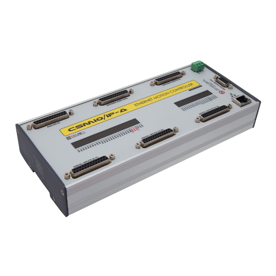
To meet customers' needs, who prefer +/- 10V servo drive control standard, the CSMIO/IP-A was equipped in such an interface, and very fast encoder inputs allow for taking full advantage of encoders with large number of pulses per rotation, and the same let you to achieve such a precision and speed, which previously were unavailable in this price sector. -
Page 7: Content
1.2 Content The CSMIO/IP-A device is placed in a cartoon box with DB->Terminal Block adapters for easier wires con- nection in a control cabinet. More content details below: CSMIO/IP-A - CNC controller • • 3x DB25Terminal block (2 pcs.) Ethernet connection wire •... -
Page 8: Standards Compliance
1.3 Standards compliance The CSMIO/IP-A controllers were designed and made in accordance with the national and international standards for industrial control systems based on electronic components: Detailed requirements for programmable controllers: working characteristics, shock resistance, • safety etc. EN61131-2 (IEC1131-2), CSA 22.2, UL508 Compliance with European Guidelines (low voltage, level of electromagnetic interference •... -
Page 9: Safety
It works both sides: if drives would not react, you always have the controller. The CSMIO/IP-A controller in active state on the input line - defined as an E-Stop stops the motion on all output channels within 1ms. -
Page 10: Example Of Direct E-Stop Signal Connection
Of course the easiest way is to connect the E-Stop only to CSMIO/IP-A but then we lose double protection and it’s no longer so safe solution. As a switch (mushroom) of emergency stop always use special switchers, specially designed for that. They have different construction and you can be actually 100% sure that the circuit will be disconnected after pressing the mushroom. -
Page 11: Example Of E-Stop Signal Connection Using Pilz Module
PNOZ X7 24 V Above you can see an example of E-Stop signal connection to the CSMIO/IP-A controller and to the axis drives, using Pilz company safety relay (PNOZ X7 24V symbol). S1 is a reset button (switching on the safe- ty relay), S2 is the emergency stop. -
Page 12: Recommendations For Mechanical Installation
3. Recommendations for mechanical installation CSMIO/IP-A controller and DB->Terminal block connection modules were designed to be installed on a standard DIN-rail. It’s the quickest and the best way of installation. The controller uses a small amount of electricity and creates a negligible amount of heat. Aluminum housing provides adequate cooling for electronics inside, even if an ambient temperature reaches 40 As for the controller, there are no special precautions for ventilation and minimum distances. -
Page 13: Control Cabinet Made By Cs-Lab Company
The wiring is doubled so we can easily switch between CSMIO/IP-A and IP-S models. C S - L a b s . c . – C S M I O / I P - A - C N C c o n t r o l l e r... -
Page 14: Connectors, Controls And Electrical Installation Of The Device
Detail description of signals on each connector is placed in the next sections. DB->Terminal block connectors have the same pin numbers as DB connectors in CSMIO/IP-A device. In example: 15 pin of DB25 connector match with the 15 pin on the terminal block. -
Page 15: Analog Inputs/Outputs Connector
4.2 Analog inputs/outputs connector PIN number Description Analog output Ch0 (+/-10V) Analog output Ch1 (+/-10V) Analog output Ch2 (+/-10V) Analog output Ch3 (+/-10V) Analog output Ch4 (+/-10V) Analog outputs for servo drives (Ch0, Analog output Ch5 (+/-10V) Ch1, Ch2, Ch3, Ch4, Ch5) always connect Analog output 0 (0-10V) with dedicated GND (GND Ch0, GND Ch1…). -
Page 16: Signals On A Terminal Block Connector
4.2.1 Signals on a Terminal Block connector Axes by default are assigned to following channels: XCh0 / YCh1 / etc. Pin numbers Entered in Mach3 program in Port&Pins” on „Motor Outputs” tab do not matter. If you want to assign other STEP/DIR channels numbers to an axis you should do it in the plugin's configuration: menu... -
Page 17: Example - Connection And Configuration Of Fro And Sro Potentiometers
4.2.2 Example – connection and configuration of FRO and SRO potentiometers Below you can see example of connection and configuration of potentiometers for feed rate correction and spindle revs regulation. As you can see in the scheme, 10V placed on the analog con- nector is very convenient and useful - thanks to it we do not need any external power supply for the potentiometers. -
Page 18: Encoder Inputs Connector (0 / 1 / 2)
Max. PINs load is +5Vto 200mA / pin. Enc. Ch0 A- Enc. Ch0 B- Enc. Ch0 I- Enc. Ch1 A- The encoder inputs of CSMIO/IP-A Enc. Ch1 B- require differential signal. If connect- Enc. Ch1 I- ed encoder has a common output then you should use special convert- Enc. -
Page 19: Signals On A Terminal Block Connector
4.3.1 Signals on a Terminal Block connector 4.3.2 Example - connection of an encoder to Ch0 channel As you can see below, although an encoder requires many wires, the rule is easy and the connection is not that hard. However the connection should be done carefully to avoid any unpleasant surprises later. C S - L a b s . - Page 20 In the example above there is a situation where to encoder input there is a motor encoder connected di- rectly. In case we use AC servo drives - to encoder input of CSMIO/IP-A you should connect encoder out- put of a servo amplifier. So connection for AC servo looks as following: [Motor encoder][servo amplifier (input)]...
-
Page 21: Encoder Inputs Connector (3 / 4 / 5)
Max PIN load is +5Vto 200mA per pin. Enc. Ch3 B- Enc. Ch3 I- Enc. Ch4 A- Enc. Ch4 B- CSMIO/IP-A encoder inputs require Enc. Ch4 I- differential signal. If encoder has common output then you must use a Enc. Ch5 A- special converter. -
Page 22: Digital Inputs Connector (0-11)
4.5 Digital inputs connector (0-11) PIN number Description Input 0 (+) Input 1 (+) Input 2 (+) Input 3 (+) Input 4 (+) Input 5 (+) Input 6 (+) Input 7 (+) Pay special attention to not exceed Input 8 (+) the permissible voltage (30VDC) on Input 9 (+) input lines. -
Page 23: Input Circuits Construction
4.5.1 Input circuits construction Below - simplified scheme of CSMIO/IP-A input circuits. On the scheme 0 – 11 Inputs are marked as IN 0 – 4.5.2 Signals on a terminal block connector C S - L a b s . c . – C S M I O / I P - A - C N C c o n t r o l l e r... -
Page 24: Examples - Input Signals Connection
4.5.3 Examples - input signals connection 4.5.3.1 PNP type inductive sensor In this example the sensor with PNP type output was connected to input no. 1. So in this case in Mach3 program we give port=10 / pin=1. 4.5.3.2 NPN type inductive sensor In this example the sensor with NPN type output was connected to input no. - Page 25 4.5.3.3 Common NC type switch In this example the NC type limit switch was connected to CSMIO/IP input no. 8. So in this case in Mach3 program we give port=10 / pin=8. C S - L a b s . c . – C S M I O / I P - A - C N C c o n t r o l l e r Page 25...
-
Page 26: Digital Inputs Connector (12-23)
4.6 Digital inputs connector (12-23) PIN number Description Input 12 (+) Input 13 (+) Input 14 (+) Input 15 (+) Input 16 (+) Input 17 (+) Input 18 (+) Input 19 (+) Pay special attention to not exceed Input 20 (+) the permissible voltage (30VDC) on Input 21 (+) input lines. -
Page 27: Digital Outputs Connector (0-15)
4.7 Digital outputs connector (0-15) PIN number Description 24V power supply for outputs: 0-3 Output 0 Output 2 24V power supply for outputs:4-7 Output 4 Output 6 24V power supply for outputs: 8-11 Output 8 The outputs have 250mA load. You Output 10 must also pay attention to large in- 24V power supply for outputs: 12-15... -
Page 28: Output Circuits Construction
4.7.1 Output circuits construction As you can see in the scheme, every output is optically isolated. The outputs are divid- ed, four in each group. Each group is controlled by specialized integrated circuit VNQ860. These circuits work in PNP logic so the high state (+24V) is the active state. -
Page 29: Example - Spindle Activation Signal
4.7.3 Example – spindle activation signal In the example below, basing on configuration of outputs that activates the spindle (M3), we can see ex- actly the following dependence: [Mach3 program signal] [CSMIO/IP signal] [Pin on CSMIO/IP connector] PIN number Description 24V Power for 0-3 outputs Output 0... -
Page 30: Expansion Modules Connector
4.8 Expansion modules connector PIN numbers Description CAN H RS232 RxD RS232 TxD CAN L RS485 B- RS485 A+ The connector is only designed for expansion modules by CS-Lab s.c. company. You shouldn't copnnect here any other devices, PC etc. C S - L a b s . -
Page 31: Power Connector
4.9 Power connector PIN number Description Power – 24V DC ground View of the plug from the side of connecting wires Pay special attention to not exceed the permissible power voltage (30VDC). It may cause damage of the device If you use in the system such inductive loads as electromagnets, solenoids, elec- tromagnetic clutches –... -
Page 32: Recommended Cables
4.11 Recommended cables Connections type Recommended cable Digital In/out Minimum cross-section 0,25mm (AWG-23) Cross-section 0,25mm (AWG-23)- shielded or pair of signal-to- Analog In/out mass wires twisted together along the entire length Encoder signals Cross-section 0,25mm (AWG-23) - shielded - twisted. Eventual- ly PC FTP cable. -
Page 33: Led Lights Meaning
4.12 LED lights meaning On the front panel of CSMIO/IP device, there are groups of LEDs that simplify verifying the correctness of electric installation and diagnostic of such components as HOME switches, LIMIT switches and safety switches (E-Stop) etc. 4.12.1 Types and location of the LEDs Digital inputs 0-23 LEDs, Error LEDs and communication ports activity LEDs Digital outputs 0-15 LEDs and device... -
Page 34: Leds State Description - Statx
Readiness state. It means that the device works correctly there are no alarm signals, such as E-Stop or LIMIT. CSMIO/IP-A waits for the commands from the It means that one or more axes are currently on a manual motion mode (JOG). -
Page 35: Example - A Scheme View Of A 3-Axis Plotter (Xyz)
4.13 Example - a scheme view of a 3-axis plotter (XYZ) 4.13.1 Power supply In the example single DC 24V power sup- ply was used. Usually there is no sense to use separate power supply for CSMIO/IP and for other components, unless there were expensive/sensitive components used in the system or components that generate much interference (large sole-... -
Page 36: Servo Drives Connection
4.13.2 Servo drives connection Below you can see sample servo drive connection. We can differentiate three basic signals functions: en- coder, analog signal +/-10V and digital control signals. Encoder signals inform the controller about current motor (axis) position. Analog +/-10V signal controls motor rpm via servo amplifier and control signals are: drive activation, fault reset and a signal that informs about alarm (e.g. -
Page 37: Limit Switches And E-Stop Signal
17-23 ‘-‘ potential for inputs: 3-9 Optical inputs in CSMIO/IP-A require both ‘+’ and ‘-‘ potentials connection. The ‘-‘ Pins of digital inputs used are connected to 0V potential - see "Power supply" section. C S - L a b s . c . – C S M I O / I P - A - C N C c o n t r o l l e r... -
Page 38: Inverter Connection Using Analog Output
DB25 – Digital outputs (0-15) Left revs switching Note that every group of CSMIO/IP-A digital outputs can work on a different potential. In this case we used 24V output of the inverter. Do no forget to set the configuration parameters of the inverter properly. Incorrect settings may cause - in the best case - the inverter error, in the worst - the spindle motor becomes permanently damaged (such damage is not covered by warranty). -
Page 39: Automatic Control Of Drives Power Supply (Hv)
The „HV Enable” voltage control function is performed automatically by the CSMIO/IP-A controller. Re- sponse time for events that cause the disconnection is less than 1ms. -
Page 40: Recommendations And Drives Selection (Motors Drives)
5. Recommendations and drives selection (motors drives) Choosing drives to work under CSMIO/IP-A control - first of all - you should make sure that they can be controlled by analog signal +/- 10V and that the drive has encoder input in differential 5V standard. It is also possible use double feedback - then we connect linear encoders mounted on machine's axes and encoder outputs from drives we leave free. -
Page 41: Precise Homing With Encoder Index Signal
6. Precise homing with encoder INDEX signal Encoder INDEX signal highly improves accuracy and repeatability of homing. As in CSMIO/IP-A it works with incremental encoders, after switching on the power the control system does not know the axes posi- tion. That is why we need to perform homing (or reference travel as other may call it). Homing precision is especially important in situation when careful workpiece machining will be stopped because of some rea- son (like power failure). -
Page 42: Lan Connection And Configuration
7.1 Direct connection to the PC CSMIO/IP-A controller can be connected directly to the PC, without any switches or routers. With this con- nection, you should remember to use the crossover cable. CSMIO/IP set includes the cable. Below – how to perform the wiring. -
Page 43: Windows ® 7 Configuration
In this window – select the „Internet protocol (TCP/IP)” position and click left mouse button • on the „Properties”. In this window enter the IP address: 10.1.1.1 and mask: 255.255.255.0. Click “OK”. • Close the window. • The network is now set to work with CSMIO/IP. •... - Page 44 Next - select „Change adapter settings”. Click with right mouse button and select “Properties” of network connection. C S - L a b s . c . – C S M I O / I P - A - C N C c o n t r o l l e r Page 44...
- Page 45 255.255.255.0. Confirm with OK. After CSMIO/IP-A controller initialize it tries to set its IP automatically at first and for that it sends request to the DHCP sever. After three failed attempts, with no response from the server- the default IP address is set to: 10.1.1.2.
-
Page 46: Local Network With Router And Dhcp
7.2 Local network with router and DHCP. If we plug the CSMIO/IP-A controller in to the computer network where is a router that allocates IP ad- dresses, the device automatically downloads the address and network mask settings. Usually there is no need to know what IP address was assigned to the device because the plug-in and the application that updates the controller software automatically searches the CSMIO/IP-A in the network. -
Page 47: Mach3 Program - General Information
Plug-ins support, which further extend functions of the program and allows for co- operation with outside motion controllers. Connection with CSMIO/IP-A controller is made by that plug-in, made by our company. Easy to use •... - Page 48 CS-Lab Company is an authorized distributor of Mach3 program in Poland. If you would like to buy the license, please contact us: biuro@cs-lab.eu. If you order CSMIO/IP-A controller and you want to order the license right away, please note it in your or- der and specify person/company, the license should be issued for.
-
Page 49: Recommended Pc Configuration
8.1 Recommended PC configuration The Mach3 program does not have any unreasonable requirements about a PC computer, unless tool paths you use take even up to tens of megabytes – then we would recommend a bit faster computer. Even simulation of a runtime with so large paths will follow more efficiently on faster PC computer. Recommended PC configuration: Processor Intel CoreDuo 2GHz •... -
Page 50: Software Installation
9. Software installation Before we begin our work, we should install the Mach3 software and plugin that ensures proper coopera- tion of the program and the CSMIO/IP controller on a PC computer. 9.1 Mach3 installation latest version Mach3 software download from ArtSoft®... -
Page 51: Microsoft ® .Net Installation (Older Operating Systems)
® 9.2 Microsoft .Net installation (older operating systems) If you use OS older than Windows® 7, it may be necessary to install Microsoft® .Net. This program is available Microsoft® website CS-Lab Company website: http://www.cs- lab.eu/en/upload/pub/dotNetFx35setup.exe For proper installation, you have to be connected to the Internet. The installation is automatic you should only approve next steps and restart your computer when it is finished. - Page 52 CSMIO/IP controller firmware that serves to controller updates. If you are not sure if you have the latest version, you can update it now. Update process was described in B Addition. If you do not want to update now deselect the „Launch CSMIO/IP-A Controller Firmware” option and click „Finish”.
-
Page 53: Administrator Rights In Windows® Vista And Windows® 7
Mach 3 plugin and CSMIO/IP-A firmware must be the same version. Update the controller firmware if needed. The update process is described in the addition section - „CSMIO/IP software updating”. 9.4 Administrator rights in Windows® Vista and Windows® 7 It is recommended to launch Mach3 program in Win- dows®... -
Page 54: Mach3 Program Configuration
10. Mach3 program configuration After software installation, you should configure it all to match the settings and the controlled machine with whole its electrical system. Elements that should be configured: Scale-up of each axis (namely how many pulses per millimeter/inch). •... -
Page 55: The First Run
You should fill in the check box and agree by clicking the button as shown in the picture. If plugin for CSMIO/IP-A was installed properly, as described in the chapter 9 - then there should this win- dow appear: Select motion controller type –... - Page 56 If during Mach3 program launching the „CSMIO/IP connection” window will appear and the „Connection status” light in the diagnostic window will flash red, it means that the CSMIO/IP-A was not found in the network. In that case, check some possible reasons: The Ethernet cable must be connected to the device before turning the power on.
-
Page 57: Configuration Of Axes Used In A Machine
Activate the X, Y, Z, A axes (the slave axis shouldn’t be activated here). Using CSMIO/IP-A controller the settings in „Motor Outputs” related to STEP/DIR signals do not matter. The only active parameter is axes enabling and disabling („Enabled” column). -
Page 58: Configuration Of Digital Input Signals
Signal polarization change, it is a selection whether the signal should be ac- tive at 0V or at 24V. Emulated Signal emulation with keyboard shortcut. In CSMIO/IP-A controller, only some signals may be emulated: „THC On”, „THC Up”, „THC Dn” and „Probe”. HotKey Keyboard shortcut for signal emulation. - Page 59 Signals that allow for motion of each axis in manual mode (movement JOG A-- in a negative direction). If you are not sure on which input in the CSMIO/IP-A is one of the signals connected, then you can open diagnostic window from the „Plugin Control/CSMIO_IP_P_plugin” menu, go to the „Digital IO”...
-
Page 60: Configuration Of Digital Output Signals
Input port number – for CSMIO/IP-A it is always port no. 10. Pin Number Pin number, means CSMIO/IP-A output number, e.g. output no. 5 of the con- troller we put here as pin no. 5. It doesn’t mean a pin number on CSMIO/IP connector. - Page 61 Universal outputs. Can be used to control a spindle, cooling as well as from VisualBasic scripts level. Current Hi/Low Current limit output for stepper motors. In CSMIO/IP-A this signal is not used. Again, during system startup the diagnostic window from the “PlugIn Control”...
-
Page 62: Configuration Of Spindle And Cooling
The last things we configure in the „Ports and Pins” window are parameters related to the control of a rotational speed through the digital input of CSMIO/IP-A. In the „ModBus Spindle – use step/dir as well” group select the „Enabled” area, in the „Reg” box enter value of 64, and in the „Max ADC count” – 4095. -
Page 63: Problematic Pwm Control Function
Last thing related to the revs control is a choice of analog output, which will be used. select from the menu „Config/Config PlugIns” • click „CONFIG” next to the „CSMIO/IP” • • go to „Spindle” tab, in the „Spindle DAC” group select „Enable”... -
Page 64: Configuration Of Resolution, Speed And Acceleration
For correct axis scaling you must know how many steps falls on a unit (millimeter, inch or degree, and if the axis is set as linear or angular). In case of CSMIO/IP-A steps number is pulses number of encoder per motor rev (with all edges). -
Page 65: Configuration Of Directions, Homing And Software Limits
Maximum range of motion in negative direction Slow Zone In CSMIO/IP-A, this field is not used. In LPT, it is used to define a section for braking near to the end of working range. CSMIO/IP-A controller automatical- ly calculates the braking distance including acceleration defined for the axis. - Page 66 When software limits option is active („Soft Limit” on a Mach3 main screen), the CSMIO/IP-A controller does not let for any move if axes of a machine are not homed. Current status of the function is shown by a green light around „Soft Limit” button.
-
Page 67: Configuration Functions In A Plug-In Window
Active signal in a Low state Input number on CSMIO/IP-A controller C S - L a b s . c . – C S M I O / I P - A - C N C c o n t r o l l e r... - Page 68 10.9.1.2 +/-10V and encoder channels selection CSMIO/IP-A controllers have six (6) +/-10V output channels and 6 encoder inputs. By default for X axis channel 0 is assigned, for Y - channel 1, for Z - channel 2 and so on.
- Page 69 Some users implement a slave axis by linking two drives. Slave axis implementation in CSMIO/IP-A has one significant advantage - available function of machine geometry correction (e.g. gantry perpendiculari- ty). It is more specifically described in the addition „Slave axis configuration example”. In brief – for each X, Y, Z-axis you can define one slave axis.
-
Page 70: Spindle Configuration
10.9.2 Spindle configuration CSMIO/IP controller has got many additional functions according to a spindle. The options were divided into following groups: Spindle DAC Selection of analog output for spindle revs control Spindle Encoder CSMIO-ENC module configuration (CSMIO_ENC) Spindle Alarm Input Spindle drive alarm signal input configuration Spindle Axis Spindle operation through axis channel (STEP/DIR) options... -
Page 71: Override Sources - Feed Speed And Spindle Revs Corrections Source Selection
If machine tool is equipped with additional panel with buttons it would be easier to adjust the speed using knobs placed on it. With CSMIO/IP-A we can also control feed speed and spindle revs using potentiometers connected to analog inputs. -
Page 72: Plasma - Additional Functions For Plasma Cutters
10.9.4 Plasma – additional functions for plasma cutters In current software version we have one option available – torch high control via analog input. Configuration is only about to enable the func- tion, select polarization, and to select analog input. The function, with normal polarization, works the way that for 0V on analog input there is correc- tion entered in THC min, and for 10V - THC max... -
Page 73: Other - Other Plugin Functions
10.9.6.2 AxesDeRef& Zero – axis reset after emergency stop Parameter used only with CSMIO/IP-S and CSMIO/IP-M. It does not matter with CSMIO/IP-A. 10.9.6.3 E-STOP requests – alarm events In this place we can disable machine stopping in following situations: •... - Page 74 10.9.6.4 Extras In CSMIO/IP software few additional functions were implemented, which increase safety and comfort of work. Auto Z-InhEnable Automatic Z axis move limitation. Enables protection against worktable of a machine damage. More details in chapter 14.1 – Automatic Tool Length Measurement. Smart Limits Movement blocking when hardware limit signal is active.
-
Page 75: Selection Of Inch/Mm Units
10.10 Selection of inch/mm units Selection of units by which the axes in „Motor Tuning” are scaled is set in „ConfigSelect Native Units” menu position. Select unit in the window and close „OK”. Selection of units for a treatment is done by G20 (inch) and G21 (mm) commands. 10.11 Some parameters in the General Config window In the „ConfigGeneral Config”... - Page 76 Home slave with mas- The intention of Mach3 authors is an option, which enable/disable slave axis and master ter axis axis homing together. In CSMIO/IP-A controller, a slave axis is always homed with mas- ter axis. G04 Dwell in ms With this option selected a delay parameter for G04 is counted in milliseconds.
-
Page 77: Pid Controller (Regulator)
11. PID controller (regulator) 11.1 What is PID controller As opposed to stepper motors which are, we can say, controlled "blindly", servo drives work in so called closed loop, so when they control a motor they check if its position is compliant with the set position. If actual rotor position differs from the expected one, there is a current correction entered to overcome the existing error. -
Page 78: Pid Controller Terms (Parameters) Operation
11.2 PID controller terms (parameters) operation There are like tens of thousands descriptions of PID controller work in the Internet, but for most of people - putting it mildly - they are rather vague and actually do not say anything. In this section we present the PID controller blocks described in a few words so you could get the logic of their operation. -
Page 79: The Derivative Term - D
• Time t=0s : output = 0 Time t=1s : output = 10 • Time t=2s : output = 20 • … • Time t=10s : output = 100 • The example above shows that even a small error may cause large offset (correction) value if it lasts for longer time. -
Page 80: The Actual Controller In Csmio/Ip-A
All the parameters that usually do not need to be tuned are marked in grey. There is also division market, where the controllers are placed. As you can see in CSMIO/IP-A there is only a position controller and "predicting" element – „V ”. -
Page 81: Pid Regulator Tuning" Window
11.5 „PID Regulator Tuning” window We tune the controller in a special window. Click on menu „ConfigConfig Plugins” and „CONFIG” at CSMIO/IP-A. Next select an axis and click “PID Tuning”. At the beginning short description of parameters and functions available in "PID Regulator tuning". - Page 82 MoveAxis Group – automatic travel to position: Pos (mm or inch) Set motion position Speed [%] Motion speed as % of maximal axis speed Acc [%] Motion acceleration as % of maximal axis acceleration Move to set position mode Move to set position and back to initial position mode Constant motion mode: to set position, to initial position, to set position …...
-
Page 83: Manual Pid Regulator Tuning Procedure In Csmio/Ip-A
If you do not feel like doing it by yourself it is better to look for help from someone more experienced. To start PID regulator tuning in CSMIO/IP-A, a machine tool should be initially configured, especially I/O signals, E-Stop should be checked as well as speed and axis scaling and acceleration. - Page 84 15% and leave this way. As in servo drives we usually use „P” and „I” controllers for velocity, in CSMIO/IP-A theoretically for posi- tion regulation the „P” parameter should be enough, but as experience say - tuning of the „I” parameter in CSMIO/IP-A increases positioning quality, regardless of the regulator used in a servo amplifier.
-
Page 85: Pid Tuning - Practical Tips
During tuning remember to click „Apply” after any value change only when these values are approved and send to CSMIO/IP-A. AT this stage the PID controller (regulator) is already tuned. Now you can decrease maximal permissible position error („Max following error”). You can set 4 x value of „Max Error” from the Monitor group. -
Page 86: Laud Noises At Standstill
If a motor does not want to work at all then we have to check a servo amplifier. Disconnect velocity signal from CSMIO/IP-A and activate an axis. Connect AA (1.5V) battery to wires and the motor should start to rotate. Change battery polarization and connect again, the motor should rotate in the other side. If it is not then check control signal from servo amplifier, usually „Enable”... -
Page 87: Autotuning - Automatic Pid Tuning
Badly tuned servo amplifier causes that correct tuning of the controller CSMIO/IP-A is IM- POSSIBLE. A servo amplifier should be tuned first and then we can tune the CSMIO/IP-A. You should re- member that autotuning in servo amplifiers very often does not work very well and is not even close to set correct parameters. - Page 88 („Max Error” in „Monitor" group). In most of cases - if servo amplifier is tuned correctly - the autotuning function in CSMIO/IP-A motion controller adjusts very good parameters and practically there is no need to tune it also manually. However there are some specific machines where the autotuning function does not want to work correctly.
-
Page 89: First Tests
If everything works correctly, press RESET on the screen and go to the next section. If there is no response for any signals, you should check if program communicates with the CSMIO/IP-A controller correctly. In the diagnos- tics window (in „PlugIn ControlCSMIO_IP_Plugin” menu) you can check the connection status. -
Page 90: Verification Of Axes Scaling And Motion Directions
12.2 Verification of axes scaling and motion directions First motion control should be made at low speed. After pressing Tab key on a key- board – manual feed rate panel should open. In „Slow Jog Rate” enter e.g. 10%. It means that the motion will have 10% of maximum speed, defined in Motor Tuning. -
Page 91: Homing And Software Limit Switches Test
12.3 HOMING and software limit switches test 12.3.1 First homing When axes are scaled correctly and motion directions are correct – it is time for first homing. During nor- mal work most comfortable is to use a button for all axes homing („Ref All Home” on the main screen). During the tests it is better to home the axes individually from the Mach Diagnostic screen. -
Page 92: Test Of Spindle And Cooling
12.4 Test of spindle and cooling. At this stage, almost all major elements of the system were set and a machine is almost ready to work. One important issue left – spindle test. Treatment with non-rotating spindle is generally not a good idea. Mach should be in active mode. -
Page 93: Sample Treatment Step By Step
13. Sample treatment step by step To look closer at rules of using a machine equipped with CSMIO/IP-A control system – here is an example of a simple work. An example includes area planning and logo milling in 30.6x30.6x48mm size cube made of hard aluminum alloy. - Page 94 The newly created object with its position and size exactly coincides with the working area. Now you should add the additional enlargement that was mentioned, so that the milling cutter will go with its whole diameter out of the material – thus we get a better surface.
- Page 95 You should inform the program what kind of tool you use. Below the Tool List click the Add button. In the tool-base window, click Add Tool, to add a new tool. Enter parameters as the pic- ture shows. Some parameters like de- scription or diameter are obvious.
- Page 96 Next, generate tool trajectory for our logo. Go back to 2D preview, and in the Toolpaths tab panel, next to the last generat- ed path – deselect Show In 2D|3D. Previous trajectory disappears so it will not disrupt our view. Now select our logo and again click the Area Clearance icon.
-
Page 97: Preparing Machine And Mach3 Program
13.2 Preparing machine and Mach3 program When files are ready, you only need to place and home the materi- al. First start Mach3 program and reference all the axes pressing „Ref All Home” button on the main screen. Place the material securely, to avoid a risk of its shifting or break- ing during the treatment. - Page 98 At this point, we can set the material base in X-axis by clicking „Zero X” button on the Mach screen. Coordinate X on the screen will be reset. Switch the feed rate mode on continuous one, „Slow Jog Rate” speed – e.g. 2% because we are very close to the material and the same way we set the Y base on the lower edge of the cube.
-
Page 99: We Begin The Treatment
13.3 We begin the treatment In Mach program, we select „File/Load G-Code” menu position or we click „Load G-Code” button on the main screen. Select the file we created earlier: „planing.tap”. When the file is loaded, we can initially set the machine over the material and enter on the MDI screen. - Page 100 Z position and type on your keyboard "0.2 <enter>". After this operation, we can start work from the second file not forgetting about the measurement after tool change („Auto Tool Zero” button). When the file is loaded, and the tool is measured we can set the axes again over the material with the MDI like before.
-
Page 101: A Few Practical Notes About Mach3 Program And Csmio/Ip-A
14. A few practical notes about Mach3 program and CSMIO/IP-A Here you can find few tips that can help users unfamiliar with Mach3 program. 1. Computer keyboard. a. Do not use a wireless keyboard, sometimes this keyboard record keystroke, but does not notice releasing it, which can be very dangerous while controlling the machine. - Page 102 a. Do not forget that pressing TAB key causes that additional side panel appears where you can set speed, continuous or step mode – it makes that controlling the axes and precise setting of material base is easier. b. By pressing the combination of feed rate key (e.g. right arrow) and SHIFT key, the movement is in continuous mode with 100% speed - regardless of the current set- tings.
- Page 103 and file manager such as Total Commander®). For any other tasks such as designing, you should use some other computer. 16. On the computer you use to control you should disable all visual effects of your desktop, screen saver, and turn power profile on “always on”. C S - L a b s .
-
Page 104: Visualbasic ® Macros
Automatic tool-length measurement is one of the most implemented function, e.g. because mechanically it is very easy to do. If high measurement accuracy is required, the sensor must be good quality. In CSMIO/IP-A controller – specialy for G31 command (used during the measurement) – we implemented completely autonomous movement operation and ultra-fast logic to assure measurement precision at the highest level. -
Page 105: Configuration
15.1.1 Configuration Before we start the script configuration, you should follow these steps: 1. Check the sensor and inputs signals settings – go to Diagnostics tab and while pushing the sen- sor with hand observe the light indicators on the screen. The light should light up at the moment of pushing the sensor and light should go out after releasing it. -
Page 106: Automatic Tool Change Macro
Parameter Details SENS_Z ] – [ Z coordinate of sensor activation Z coordinate of table level If you e.g. when reaching the table Z=-122.070mm, and sensor gave an active signal at Z=-110.656mm – the entered value should be 11.414. Z_SAFE It is parameter that describes at what height the Z axis can slide down fast (G0). -
Page 107: Addition A - Slave Axis Configuration Example
With bigger machines you often need to use so called – slave axis. It is about that the physical axis of the machine is powered by two motors. We implemented in CSMIO/IP-A device the slave axes function with additional option to adjust geometry of a machine. Geometry regulation is very useful if you want to set perpendicular axes precisely. -
Page 108: Limit And Homing Switches
LIMIT and HOMING switches On both – slave and master axes side – there should be separate LIMIT and HOME switches. The signals should be properly set in Mach3 program („ConfigPorts and Pins”). Before next steps it is necessary to verify if the signals are correctly configured (DIAGNOSTICS tab) Pay special attention whether HOMING switches are not replaced. -
Page 109: Geometry Correction Mode Activation
With servo-drives, you should always have alarm signals configured correctly. CS-Lab Company made every effort to ensure reliability of CSMIO/IP-A controller. However, our company does not take any responsibility for any mechanics damage because of wrong configuration and any even- tual failure or software errors of CSMIO/IP-A controller. -
Page 110: Addition B - -Csmio/Ip-A Firmware Update
(x.xxx is a firmware version). Installation process was described in chapter „9.3 – Installation of CSMIO/IP software”. At the end of installation leave „Launch CSMIO/IP-A Controller Firmware” option selected and click „Fin- ish”. The application will be launched automatically, thanks to it we update CSMIO/IP software. Below you can see the application window and sequence of actions that should be done. -
Page 111: Plugin File Update
If there are more controllers then you should chose one IP address from a list to update the controller you want and click „Flash Program”. CSMIO/IP-A controller is protected if update fails. There is always a possibility to try again Before update – close Mach3 program.
Need help?
Do you have a question about the CSMIO/IP-A and is the answer not in the manual?
Questions and answers