
Related Manuals for CS-Lab SimDrive M4-H075K


Summary of Contents for CS-Lab SimDrive M4-H075K
- Page 1 Applies to hardware version : v1 Applies to firmware version : v2.00 Rev 1.0 © copyright 2014 – CS-Lab s.c.
-
Page 2: Table Of Contents
INDEX 1. Introduction .......................... 4 1.1 Signs used in this guide ......................4 1.2 Standards compliance ......................4 1.3 Technical data sheet ........................ 5 1.4 Drive and brushless motor running - checklist ................ 6 2. Block connection scheme ...................... 8 2.1 Brushless motors (AC / BLDC) .................... - Page 3 5.4 Motor parameters configuration ................... 29 5.4.1 Motor type ........................29 5.4.2 Nominal motor parameters ........Błąd! Nie zdefiniowano zakładki. 5.4.3 Brushless motor parameters (AC/BLDC) ..............30 5.4.4 Motor constants ......................31 5.4.5 Coupling (Incremental encoder) .................. 31 5.4.6 HALL sensors – rotor position coupling ................ 31 5.4.7 Reference signal (STEP/DIR) ..................
-
Page 4: Introduction
1. Introduction 1.1 Signs used in this guide __________________________________________________________________________________ Potential danger and/or possible injury risk __________________________________________________________________________________ Useful information, tips __________________________________________________________________________________ Warning, failure to comply with these warnings may lead to inappropriate functioning or damage of the device __________________________________________________________________________________ 1.2 Standards compliance simDrive™... -
Page 5: Technical Data Sheet
10% do 95% (without condensation) Recommended power supplying way is 230V AC power supply by CS-Lab s.c. company. The difference between maximal drive power and recommended motor comes from the fact that the drive should have some power reserves to be able to overload the motor. The second reason is limitation of heat given off from the drive. -
Page 6: Drive And Brushless Motor Running - Checklist
CAN bus then you have to set addresses for the drives – read chapter 5.2.2 - „Connection through the CAN bus" If the motor supplier is CS-Lab s.c. company load configuration template for the particular model (available on www.cs-lab.eu) and save the configuration in non-volatile memory by pressing icon. - Page 7 "Reference Position" counter should increase or decrease its value - it depends on motion direction in CNC software. If it is a motor bought from CS-Lab s.c. and configuration template had been loaded before - you can skip this point.
-
Page 8: Block Connection Scheme
2. Block connection scheme Below you will find connection demonstration scheme of three-phase brushless motor (AC) and brushed motor (DC). It is easy to notice that both schemes are almost the same. For DC motor we use only extreme phases for power supply (U and W) of which we connect DC motor „+”... -
Page 9: Brushless Motors (Ac / Bldc)
2.1 Brushless motors (AC / BLDC) simDrive™ AC Servo Drive - U UIDE... -
Page 10: Brushed Motors (Dc)
2.2 Brushed motors (DC) simDrive™ - AC Servo Drive User Guide... -
Page 11: Pins Description On Drive Connectors
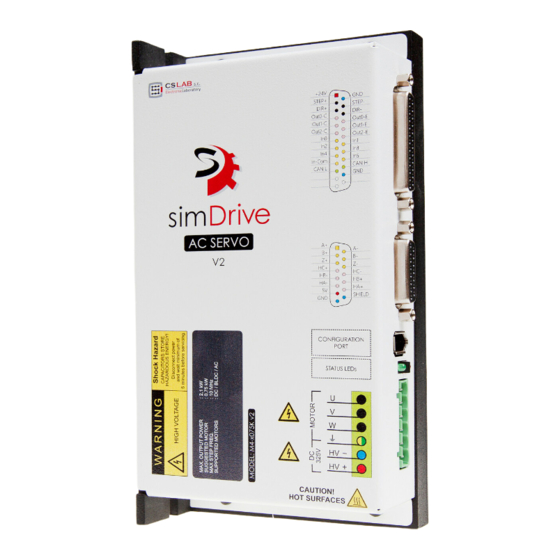
3. PINs description on drive connectors 3.1 Connectors arrangement (M4-…040K model) CN3 – power output stage connector CAN and CAN connector configuration CN1 – Signal connector 3.2 Connectors arrangement (M4-…075K model) CN3 – Power output stage connector CN2 – Configuration connector CN1 –... -
Page 12: Cn1 - Signals Connector
3.3 CN1 - Signals connector Front view of the drive's connector/ from the soldering side Signal Description number +24V Logic power supply (24V DC) STEP+ Step signal (positive input of an optocoupler) DIR+ Direction signal (positive input of an optocoupler) Digital output 0 (Collector) [Alarm] OUT0 [C] Digital output 1 ( Collector ) [# Homing - output]... -
Page 13: Cn2 - Communication Connector (Model M4
If it's necessary to connect the mentioned signals in 24V standard then please contact with CS-Lab company first to consult and select correct converter. Next to the digital inputs and outputs there are default functions assigned in square brackets. The ‘#’... -
Page 14: Cn3 - Power Output Stage Connector
3.5 CN3 - power output stage connector Connector view from the top Signal Description number HV(+) (+) Power supply of power output stage HV(-) (-) Power supply of power output stage Ground Motor power supply (W phase) Motor power supply (V phase) Motor power supply (U phase) 3.6 CN4 - CAN connector (model M4-…040K) Front view of the device's... -
Page 15: Cn5 -Can And Configuration Connector (Model M4
3.7 CN5 –CAN and configuration connector (model M4-…040K) Front view of the device's connector Signal Description number RS232 – diagnostics and configuration RS232 – diagnostics and configuration CAN H CAN bus (H signal) GND (0V) CAN L CAN bus (L signal) (housing) Shield Wire shielding... -
Page 16: I/O Circuits Internal Construction
4. I/O circuits internal construction 4.1.1 Encoder inputs 4.1.2 HALL sensors inputs 4.1.3 STEP/DIR control signals inputs simDrive™ - AC Servo Drive User Guide... -
Page 17: Digital Inputs In0 - In5
4.1.4 Digital inputs IN0 – IN5 4.1.5 Digital outputs OUT0 – OUT2 simDrive™ AC Servo Drive - U UIDE... -
Page 18: Starting And Configuration
The converter and the cable are not required for configuration if the drive is used with CSMIO/IP - CNC motion controller by CS-Lab company and connected with the controller via CAN bus (chapter 5.2.2 –... -
Page 19: Configuration - Diagnostic Software Utility Installation
5.1 Configuration - diagnostic software utility installation 5.1.1 USB-RS232 converter installation If we use USB-RS232 converter purchased from CS-Lab company we should install driver first. USB-RS232 converter driver setup program is installed during simDrive™ Software Package setup by default. When simDrive™ setup finishes you can click on windows start menu and find: “simDrive Software Package / Install USB-Serial Converter”... -
Page 20: Csservomanager Utility Software Installation
Start the csServoManagerSetup.exe file downloaded from www.cs-lab.eu/en or provided on a CD attached to a package. Then click „Next >” till the end of the installation process. 5.2 csServoManager - general rules and notes In csServoManager utility software there were only necessary options implemented for configuration and diagnostics. -
Page 21: Can Bus Connection
5.2.2 CAN bus connection The principle of simDrive and CSMIO/IP controller connection through CAN bus The most convenient way of connection is connection via CAN bus and CSMIO/IP controller. You only have to set drives addresses first. The addresses range is: 104 - 109 (we recommend keeping the order with axis signs, so: 104 for X axis, 105 for Y axis, and so on). -
Page 22: Toolbar
5.2.3 Toolbar The most frequently used functions are available on a toolbar so this way you have easy access to them. The icons have the following functions assigned (from the left): ICON Corresponding menu function Description Disconnection/connection with a drive. If e.g. we have finished configuration of one drive and we want to start another then we click the icon to disconnect. - Page 23 motor. Tools Show alarms It opens a window with an alarms list. It opens a window for PID regulators Configuration PID tuning tuning. Configuration Motor Motor parameters settings. parameters Drive's digital inputs and outputs Configuration IO Signals configuration.
-
Page 24: State Bar
5.2.4 Status bar The status bar shows current state and drive connection details. 5.2.4.1 Connection state icons Icon Description No connection. This sign blinking means connection attempt. If it lights up constantly it means connection was established and is active. 5.2.4.2 Connection interface Sign Description... -
Page 25: Entering Numerical Values
5.2.5 Entering numerical values After we enter the value into text area we should always approve it with „Enter” key. Only then the new parameter value will be transmitted to simDrive device. We are able to see if the edited parameter value was approved looking at text area backlight. -
Page 26: Parameters Monitor" Window - Real-Time Parameters Preview
5.3 „Parameters Monitor” window – real-time parameters preview During drive configuration it's very useful to have the possibility to watch the parameters and information about them up-to-date. We call the preview window by clicking the icon on the toolbar or by selecting „ToolsParameters Monitor”... - Page 27 Here is a list of parameters which preview is available with their short description. PARAMETER NAME DESCRIPTION Firmware version Drive firmware version Drive status Current drive state Alerts. Detailed alerts description in menu „ToolsShow Alarm flags Alerts” or after pressing the icon on the toolbar.
- Page 28 defined by HALL sensor. Absolute difference between the angle and electrical angle from encoder shouldn't exceed . Higher value means incorrect configuration of HALL sensors, wrong order of HALL sensors connection, or interferences on an encoder caused by poor quality wiring. (Brushless motors only).
-
Page 29: Motor Parameters Configuration
We strongly recommend to use simDrive™ 325 VDC servo drives together with motors offered by CS-Lab company. There are configuration templates for these motors ready for download and thanks to them we do not need to set the motor parameters ourselves. -
Page 30: Brushless Motor Parameters (Ac/Bldc)
Nominal motor current. The value should be also placed on a Current motor nameplate. By entering incorrect values in this group you can permanently damage the motor. CS-Lab s.c. company does not take any responsibility for damage caused by incorrect drive configuration. 5.4.3 Brushless motor parameters (AC/BLDC) This group applies only to brushless motors. -
Page 31: Motor Constants
5.4.4 Motor constants Parameter name Description Motor torque constant stated in Nm/A. If you do not have Torque constant documentation of your motor then enter 0. Voltage constant stated in V/1000RPM. If you don't know this value you can enter 0 but it will decrease positioning quality at dynamic acceleration/braking. -
Page 32: Reference Signal (Step/Dir)
5.4.7 Reference signal (STEP/DIR) Parameter name Description Change of motor revs direction. The parameter affects only Invert dir external STEP/DIR signal control. Sometimes the connected motor have a high resolution encoder - e.g. 40000 ������ 5.4.8 Electronic gearing ������ and a CNC encoder has 3000 nominal revs and 5000 ������... -
Page 33: Digital Inputs/Outputs Configuration
5.5 Digital inputs/outputs configuration If we have already set motor parameters then it is time for digital inputs and outputs settings unless the signals were connected in accordance with default settings (chapter 5.5.2 and 5.5.4). I/O configuration window can be called out from the menu: „Configuration ... -
Page 34: Digital Inputs Function
5.5.1 Digital inputs function Description Default state Function E-Stop Emergency stop Inactive Homing signal input Home In (for doming signal and encoder index Active synchronization) Reset Alarm reset Inactive Załączanie końcówki mocy – przejście ze Servo ON Active stanu gotowości do stanu pracy Limit++ Positive limit Inactive... -
Page 35: Pid Regulator Tuning
5.6 PID controller tuning For beginners it's the hardest stage of the configuration but following the manual even they can tune the PID controller properly and pretty fast. Before we enter power output stage (HV) and we switch a servo drive on („Servo ON”) we should first enter initial, low values of the controller to avoid loud motor oscillation right after we turn the motor. -
Page 36: Manual Pid Regulator Tuning Procedure
5.6.2 Manual PID controller tuning procedure You should connect power output stage power supply (HV), however be ready to disconnect the power supply in case if something was set incorrectly and motor will start to vibrate or rotate uncontrollably. You can use JOG function directly from csServoManager (ToolsJOG I/O control) during tuning. Step by step tuning process looks as follows: •... - Page 37 • Leave the „JOG” tab and go to „Motion planner” and 100 RPM velocity and about 1500 RPM/s acceleration, position equal to encoder impulses per rev number (1 motor revolution) set “Relative”. • Make sure if the motion in 1 motor revolution range won’t cause damage of a machine axis mechanics and if any other person doesn’t work at the axis as a motor will start to rotate in a...
- Page 38 In most of cases at this stage of the tuning the procedure is finished but for new machines or machines that were not used for a long time probably you will have to tune current and position controller once again when mechanics is livened up and run in. In case an axis has a tendency to go into vibrations you can try to suppress them by increasing K gain of velocity controller.
-
Page 39: Automatic Pid Regulator Tuning Procedure
5.6.3 Automatic PID regulator tuning procedure simDrive servo driver allows for automatic PID regulator tuning. At the beginning we should notice that due to variety of motors and mechanical systems the autotuning may not work property for every one of them and it may be necessary to tune the PID manually. - Page 40 5.6.3.1 Autotuning configuration parameters Description Parameter Max motion velocity during autotuning. By default it is 500 RPM, if such Velocity rotation speed in not safe for a machine or it exceeds motor capacity then you should decrease it. Autotuning acceleration. By default 3000 RPM/s. For small accelerations Acceleration the autotuning may be less precise so you should decrease the parameter only if it is absolutely necessary.
-
Page 41: Torque Scan Function - Cstorquescan
5.7 Torque scan function - csTorqueScan™ Some motors have large torque ripple in a rev angle function. simDrive servo drive enables a measurement of these ripples and lets for proper compensation entering in a real time. It makes positioning is more precise and vibrations are suppressed (without the compensation the vibrations would occur at some velocity ranges). - Page 42 The ripples measurement procedure requires a motor to be in motion and mechanically mounted on a machine so you need to be careful and verify if there is enough space for the motion (by default a motor during autotuning rotate by +/- 0,5 of a rev) and also if no one else works on the machine at the moment.
-
Page 43: Drive Alarm Flags Description
In the second situation we should decrease DC bus acceleration in a CNC controller, increase capacitors capacitance in a power supply or to use a special power module by CS-Lab company that allows for braking resistor connection. Overload. Motor input current was exceeded for too long (chapter 7 - „Drive overload characteristic”. -
Page 44: Drive Overload Characteristic
Alarm name Description CRC32 control value in device memory was incompatible and Configuration read- default settings were loaded. It means drive’s settings loss and/or out error, default non-volatile memory of a device malfunction. If the problem settings loaded persists after another configuration – contact with service. EEPROM memory Non-volatile memory breakdown. -
Page 45: A Addition - Firmware Update
8. A addition - Firmware update Firmware updates can be downloaded here: http://www.cs-lab.eu. The .zip archives include: • Up to date configuration – diagnostics utility - csServoManager™ (install version) • simDrive™ servo driver firmware files (firmware) • Uploader which is a software for simDrive™ firmware updating 8.1 csServoManager™... -
Page 46: B Addition - What Is Pid Controller (Regulator)
9. B addition - What is PID controller (regulator) 9.1 What is PID controller As opposed to stepper motors which are, we can say, controlled "blindly", servo drives work in so called closed loop, so when they control a motor they check if its position is compliant with the set position. -
Page 47: Pid Controller Terms (Parameters) Operation
9.2 PID controller terms (parameters) operation There are like tens of thousands descriptions of PID controller work in the Internet, but for most of people - putting it mildly - they are rather vague and actually do not say anything. In this section we present the PID controller blocks described in a few words so you could get the logic of their operation. -
Page 48: The Derivative Term - D
• Time t=2s : output = 20 • … • Time t=10s : output = 100 The example above shows that even a small error may cause large offset (correction) value if it lasts for longer time. In practice we deal not with seconds but with fraction of seconds because the PID controllers work from a few hundred to several thousand times per second. -
Page 49: C Addition - Slave Axis
10. C addition – Slave axis Many drives have so called slave axis function available used by mechanics, installers, operators for slave axis implementation in CNC machines in which single axis is driven by two motors. This is not always an optimal solution as these both motors work then like they were mechanically connected. -
Page 50: D Addition - Diagnostics Via Mach3 Software
11. D addition – Diagnostics via Mach3 software simDrive™ servo drive can be connected through CAN bus with dedicated CNC controller – CSMIO/IP-S. In current firmware version it lets for the drive diagnostics directly in Mach3 and there is no need to use USB-RS232 or to start csServoManager™.
Need help?
Do you have a question about the SimDrive M4-H075K and is the answer not in the manual?
Questions and answers