Vega VEGAPULS 62 Operating Instructions Manual
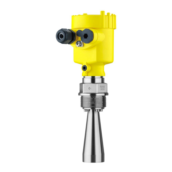
Radar sensor for continuous level
measurement of liquids.
4...20 ma/hart - two-wire
approval according to lpr radio standard
Hide thumbs
Also See for VEGAPULS 62:
- Operating instructions manual (104 pages) ,
- Quick setup manual (24 pages) ,
- Safety instruction (16 pages)

Related Manuals for Vega VEGAPULS 62


Summary of Contents for Vega VEGAPULS 62
-
Page 1: Operating Instructions
Operating Instructions Radar sensor for continuous level measurement of liquids VEGAPULS 62 4 … 20 mA/HART - two-wire Approval according to LPR radio standard Document ID: 41718... -
Page 2: Table Of Contents
Parameter adjustment ....................52 Saving the parameter adjustment data ................53 Set up with other systems DD adjustment programs ....................54 Field Communicator 375, 475 ..................54 Diagnosis, asset management and service VEGAPULS 62 • 4 … 20 mA/HART - two-wire... - Page 3 11.3 Dimensions ........................75 Safety instructions for Ex areas Please note the Ex-specific safety information for installation and op- eration in Ex areas. These safety instructions are part of the operating instructions manual and come with the Ex-approved instruments. Editing status: 2014-01-28 VEGAPULS 62 • 4 … 20 mA/HART - two-wire...
-
Page 4: About This Document
This arrow indicates a single action. Sequence of actions Numbers set in front indicate successive steps in a procedure. Battery disposal This symbol indicates special information about the disposal of bat- teries and accumulators. VEGAPULS 62 • 4 … 20 mA/HART - two-wire... -
Page 5: For Your Safety
During work on and with the device the required personal protective equipment must always be worn. Appropriate use VEGAPULS 62 is a sensor for continuous level measurement. You can find detailed information about the area of application in chapter "Product description". Operational reliability is ensured only if the instrument is properly used according to the specifications in the operating instructions manual as well as possible supplementary instructions. -
Page 6: Ce Conformity
Latvia, Luxembourg, Malta, Netherlands, Norway, Poland, Portugal, Romania, Sweden, Switzerland, Slovakia, Slovenia, Spain, Czech Republik and Cyprus. Not included in the CE confirmity declaration are the countries imple- menting this radio standard at a later date: Finland and Hungary. For operation outside of closed vessels, the following conditions must be fulfilled: • The installation must be carried out by trained qualified personnel VEGAPULS 62 • 4 … 20 mA/HART - two-wire... -
Page 7: Radio License For Usa/Canada
That is why we have introduced an environment management system with the goal of continuously improving company environmental pro- tection. The environment management system is certified according to DIN EN ISO 14001. Please help us fulfill this obligation by observing the environmental instructions in this manual: • Chapter "Packaging, transport and storage" • Chapter "Disposal" VEGAPULS 62 • 4 … 20 mA/HART - two-wire... -
Page 8: Product Description
Operating instructions and quick setup guide at the time of ship- ment (PDF) • Order-specific sensor data for an electronics exchange (XML) • Test certificate (PDF) - optional Go to www.vega.com, "VEGA Tools" and "Instrument search". Enter the serial number. Alternatively, you can access the data via your smartphone: VEGAPULS 62 • 4 … 20 mA/HART - two-wire... -
Page 9: Principle Of Operation
– Driver software Principle of operation Application area The VEGAPULS 62 radar sensor can be used in a wide variety of ap- plications for continuous level measurement of liquids. It is suitable for applications in storage vessels, reactors and process vessels, even under extremely difficult process conditions. -
Page 10: Packaging, Transport And Storage
PACTware with VEGA-DTM is required. You can find further information in the operating instructions "Interface adapter VEGACONNECT" (Document-ID 32628). VEGADIS 81 The VEGADIS 81 is an external display and adjustment unit for VEGA plics sensors. ® VEGAPULS 62 • 4 … 20 mA/HART - two-wire... - Page 11 JIS B 2210-1984, GOST 12821-80. You can find additional information in the supplementary instructions manual "Flanges according to DIN-EN-ASME-JIS" (Document-ID 31088). Electronics module The electronics module VEGAPULS series 60 is a replacement part for radar sensors of VEGAPULS series 60. There is a different version available for each type of signal output. You can find further information in the operating instructions "Elec- tronics module VEGAPULS series 60" (Document-ID 36801). VEGAPULS 62 • 4 … 20 mA/HART - two-wire...
- Page 12 You can find further information in the operating instructions "Supple- mentary electronics for 4 … 20 mA/HART - two-wire" (Document-ID 42764). Antenna impedance cone The antenna impedance cone is a replacement part used for optimum transmission of microwaves and for sealing against the process. You find further information in the operating instructions "Antenna impedance cone VEGAPULS 62 and 68" (Document-ID 31381). VEGAPULS 62 • 4 … 20 mA/HART - two-wire...
-
Page 13: Mounting
The instrument is also available in versions with an antenna whose diameter is larger than the process fitting (thread, flange). In such cases the antenna must be disconnected from the process fitting before mounting. Proceed as follows: 1. Loosen the hexagon socket screws (3) on the antenna socket with an Allen wrench (size 3) 2. Remove the antenna (4) VEGAPULS 62 • 4 … 20 mA/HART - two-wire... -
Page 14: Mounting Instructions
Hexagon screws on the antenna socket Antenna Mounting instructions Polarisation The emitted radar impulses of the radar sensor are electromagnetic waves. The polarisation is the direction of the electrical wave compo- nent. By turning the instrument in the connection flange or mounting boss, the polarisation can be used to reduce the effects of false echoes. The position of the polarisation is marked on the process fitting of the instrument. VEGAPULS 62 • 4 … 20 mA/HART - two-wire... - Page 15 In vessels with conical bottom it can be advantageous to mount the sensor in the center of the vessel, as measurement is then possible down to the lowest point of the vessel bottom. VEGAPULS 62 • 4 … 20 mA/HART - two-wire...
- Page 16 Fig. 6: Mounting of the radar sensor with inflowing medium Socket The socket piece should be dimensioned in such a way that the antenna end protrudes slightly out of the socket. Fig. 7: Recommended socket mounting with horn antenna VEGAPULS 62 • 4 … 20 mA/HART - two-wire...
- Page 17 The instrument is also optionally available with an antenna extension. The antenna length can be selected (either ex works or later) to allow the antenna to protrude slightly out of the end of the mounting socket. VEGAPULS 62 • 4 … 20 mA/HART - two-wire...
- Page 18 Small, inclined sheet metal baffles above the installations scatter the radar signals and prevent direct interfering reflections. Fig. 11: Cover smooth profiles with deflectors Agitators If there are agitators in the vessel, a false signal suppression should be carried out with the agitators in motion. This ensures that the interfering reflections from the agitators are saved with the blades in different positions. VEGAPULS 62 • 4 … 20 mA/HART - two-wire...
- Page 19 As an alternative, sensors with guided microwave can be used. These are unaffected by foam generation and are best suited for such ap- plications. Measurement in a surge When using a surge pipe in a vessel, influences from vessel installa- pipe tions and turbulences can be excluded. Under these prerequisites, the measurement of products with low dielectric values (ε value ≥ 1.6) is possible. In very adhesive products, measurement in a surge pipe is not recommended. VEGAPULS 62 • 4 … 20 mA/HART - two-wire...
- Page 20 For the parameter adjustment, select "Application standpipe" and enter the tube diameter to compensate errors due to running time shift • A false signal suppression with integrated sensor is recommended but not mandatory VEGAPULS 62 • 4 … 20 mA/HART - two-wire...
- Page 21 • Diameter should be constant over the complete length Measurement in the An alternative to measurement in a surge pipe is measurement in a bypass bypass tube outside of the vessel. VEGAPULS 62 • 4 … 20 mA/HART - two-wire...
- Page 22 • A false signal suppression with integrated sensor is recommended but not mandatory • The measurement through a ball valve with complete run is pos- sible VEGAPULS 62 • 4 … 20 mA/HART - two-wire...
- Page 23 Only then, a reliable temperature decoupling is guaranteed. Fig. 15: Mounting the instrument on insulated vessels. 1 Electronics housing Distance piece Vessel insulation Flow measurement with The short examples give you introductory information on the flow rectangular flume measurement. Detailed planning information is available from flume manufacturers and in special literature. VEGAPULS 62 • 4 … 20 mA/HART - two-wire...
- Page 24 In general, the following points must be observed: • Install the sensor on the headwater side • Installation in the centre of the flume and vertical to the liquid surface • Distance to the overfall orifice • Distance of orifice opening above ground • Min. distance of the orifice opening to bottom water • Min. distance of the sensor to max. storage level VEGAPULS 62 • 4 … 20 mA/HART - two-wire...
- Page 25 In general, the following points must be observed: • Installation of the sensor at the input side • Installation in the centre of the flume and vertical to the liquid surface • Distance to the Venturi flume • Min. distance of the sensor to max. storage level VEGAPULS 62 • 4 … 20 mA/HART - two-wire...
-
Page 26: Connecting To Power Supply
With Ex systems, the grounding is carried out according to the instal- lation regulations. In electroplating and CCP systems (cathodic corrosion protection) it must be taken into account that significant potential differences exist. This can lead to unacceptably high shield currents if the cable shield is grounded at both ends. VEGAPULS 62 • 4 … 20 mA/HART - two-wire... -
Page 27: Connecting
1 cm (0.4 in) of insulation from the ends of the individual wires 5. Insert the cable into the sensor through the cable entry Fig. 18: Connection steps 5 and 6 - Single chamber housing VEGAPULS 62 • 4 … 20 mA/HART - two-wire... -
Page 28: Wiring Plan, Single Chamber Housing
10. Reinsert the display and adjustment module, if one was installed 11. Screw the housing cover back on The electrical connection is finished. Wiring plan, single chamber housing The following illustration applies to the non-Ex as well as to the Ex-ia version. VEGAPULS 62 • 4 … 20 mA/HART - two-wire... -
Page 29: Wiring Plan, Double Chamber Housing
Internal connection to the connection compartment For display and adjustment module or interface adapter Information: The connection of an external display and adjustment unit is not pos- sible with this double chamber housing. VEGAPULS 62 • 4 … 20 mA/HART - two-wire... - Page 30 The use of an external display and adjustment unit and a display and adjustment module in parallel in the connection compartment is not supported. Connection compartment - Radio module PLICS- MOBILE Status SIM-Card Test Fig. 23: Connection compartment radio module PLICSMOBILE Voltage supply You can find detailed information on connection in the supplementary instructions "PLICSMOBILE GSM/GPRS radio module". VEGAPULS 62 • 4 … 20 mA/HART - two-wire...
-
Page 31: Wiring Plan, Double Chamber Housing Ex D Ia
Terminal compartment 4...20mA Fig. 25: Connection compartment, double chamber housing Ex d ia Voltage supply, signal output 2 Ground terminal for connection of the cable screen Plug M12 x 1 for external display and adjustment unit Fig. 26: Top view of the plug connector Pin 1 Pin 2 Pin 3 Pin 4 VEGAPULS 62 • 4 … 20 mA/HART - two-wire... -
Page 32: Double Chamber Housing With Dis-Adapt
Pin 1 Pin 2 Pin 3 Pin 4 Contact pin Colour connection ca- Terminal, electronics ble in the sensor module Pin 1 Brown Pin 2 White Pin 3 Blue Pin 4 Black VEGAPULS 62 • 4 … 20 mA/HART - two-wire... -
Page 33: Wiring Plan - Version Ip 66/Ip 68, 1 Bar
As soon as a plausible measured value is found, the corresponding current is outputted to the signal cable. The value corresponds to the actual level as well as the settings already carried out, e.g. factory setting. VEGAPULS 62 • 4 … 20 mA/HART - two-wire... -
Page 34: Set Up With The Display And Adjustment Module
The display and adjustment module is powered by the sensor, an ad- ditional connection is not necessary. Fig. 30: Installing the display and adjustment module in the electronics compart- ment of the single chamber housing VEGAPULS 62 • 4 … 20 mA/HART - two-wire... -
Page 35: Adjustment System
Adjustment system Fig. 32: Display and adjustment elements LC display Adjustment keys • Key functions [OK] key: – Move to the menu overview VEGAPULS 62 • 4 … 20 mA/HART - two-wire... -
Page 36: Parameter Adjustment
"Setup", "Diagnosis" and "Additional set- tings" are described. The general parameters in these menu section are described in the operating instructions manual "Indicating and adjustment module". VEGAPULS 62 • 4 … 20 mA/HART - two-wire... - Page 37 The adjustment possibilities depend on the selection "Liquid" or "Bulk solid" under "Medium". The following options are available when "Liquid" is selected: The selection "Standpipe" opens a new window in which the inner diameter of the applied standpipe is entered. VEGAPULS 62 • 4 … 20 mA/HART - two-wire...
- Page 38 – Slight sensitivity against sporadic false echoes – Stable and reliable measured values by averaging – High accuracy – False signal suppression required Stirrer vessel (reactor): • Setup: all vessel sizes possible • Product speed: VEGAPULS 62 • 4 … 20 mA/HART - two-wire...
- Page 39 – Often the level is hold via a control facility • Vessel: – Lateral outlets and inlets – Joins like flanges, weld joints – Shifting of the running time in the tube • Process/measurement conditions: – Condensation VEGAPULS 62 • 4 … 20 mA/HART - two-wire...
- Page 40 • Gauge rate of change: slow gauge change • Process/measurement conditions: – Ice and condensation on the antenna possible – Spiders and insect nestle in the antennas – Smooth water surface VEGAPULS 62 • 4 … 20 mA/HART - two-wire...
- Page 41 Vessel of metal: weld joints • Process/measurement conditions: – Filling too close to the sensor – System noise with completely empty silo increased • Properties, sensor: – Stable measured values through higher averaging VEGAPULS 62 • 4 … 20 mA/HART - two-wire...
- Page 42 – Measured value jumps, e.g. by truck loading – Fast reaction time – Large distance to the medium • Properties, sensor: – Little averaging – Max. reaction speed, very high measured value jumps are accepted VEGAPULS 62 • 4 … 20 mA/HART - two-wire...
- Page 43 To perform the adjustment, enter the distance with full and empty ves- sel, see the following example: VEGAPULS 62 • 4 … 20 mA/HART - two-wire...
- Page 44 2. Edit the percentage value with [OK] and set the cursor to the requested position with [->]. 3. Set the requested percentage value with [+] and save with [OK]. The cursor jumps now to the distance value. VEGAPULS 62 • 4 … 20 mA/HART - two-wire...
- Page 45 The measurement reliability equals signal strength minus noise. The higher the value, the more reliable the measurement. With a function- ing measurement, the values are > 10 dB. VEGAPULS 62 • 4 … 20 mA/HART - two-wire...
- Page 46 Additional adjustments - The following circumstances cause interfering reflections and can False signal suppression influence the measurement: • High sockets • Vessel installations such as struts • Agitators • Buildup or welded joints on vessel walls VEGAPULS 62 • 4 … 20 mA/HART - two-wire...
- Page 47 The menu item "Delete" is used to completely delete an already cre- ated false signal suppression. This is useful if the saved false signal suppression no longer matches the metrological conditions in the vessel. VEGAPULS 62 • 4 … 20 mA/HART - two-wire...
- Page 48 Any stored false signal suppression, user programmable linearization curve as well as the measured value memory is deleted. Setup: Resetting of the parameter settings to the default values of the respective instrument in the menu item Setup. User-generated false VEGAPULS 62 • 4 … 20 mA/HART - two-wire...
- Page 49 Min. current 3.8 mA, max. current Min./Max. 20.5 mA Block adjustment Released Display Language Like order Displayed value Distance Display unit Scaling size Volume Scaling 0.00 lin %, 0 l 100.00 lin %, 100 l Backlight Switched off VEGAPULS 62 • 4 … 20 mA/HART - two-wire...
-
Page 50: Saving The Parameter Adjustment Data
If it is necessary to exchange a sensor, the display and adjustment module is inserted into the replacement instrument and the data are likewise written into the sensor via the menu item "Copy sensor data". VEGAPULS 62 • 4 … 20 mA/HART - two-wire... -
Page 51: Setup With Pactware
5 Interface adapter, for example VEGACONNECT 4 Note: With power supply units with integrated HART resistance (internal resistance approx. 250 Ω), an additional external resistance is not necessary. This applies, e.g. to the VEGA instruments VEGATRENN 149A, VEGAMET 381, VEGAMET 391. Common Ex separators are also usually equipped with a sufficient current limitation resistance. In VEGAPULS 62 • 4 … 20 mA/HART - two-wire... -
Page 52: Parameter Adjustment
Saving/printing the project as well as import/export functions are also part of the standard version. In the full version there is also an extended print function for complete project documentation as well as a save function for measured value VEGAPULS 62 • 4 … 20 mA/HART - two-wire... -
Page 53: Saving The Parameter Adjustment Data
CD from the agency serving you. Saving the parameter adjustment data We recommend documenting or saving the parameter adjustment data via PACTware. That way the data are available for multiple use or service purposes. VEGAPULS 62 • 4 … 20 mA/HART - two-wire... -
Page 54: Set Up With Other Systems
This software is updated via the Internet and new EDDs are automatically taken over into the device catalogue of this software after they are released by the manufacturer. They can then be transferred to a Field Communicator. VEGAPULS 62 • 4 … 20 mA/HART - two-wire... -
Page 55: Diagnosis, Asset Management And Service
Changes in the measure- ment conditions during operation or buildup on the sensor can thus be recognized. The echo curve of the setup is stored via: • PC with PACTware/DTM • Control system with EDD • Display and adjustment module VEGAPULS 62 • 4 … 20 mA/HART - two-wire... -
Page 56: Asset Management Function
This status message is inactive by default. It can be activated by the user via PACTware/DTM or EDD. Maintenance: Due to external influences, the instrument function is limited. The measurement is affected, but the measured value is still valid. Plan in maintenance for the instrument because a failure is expected in the near future (e.g. due to buildup). VEGAPULS 62 • 4 … 20 mA/HART - two-wire... - Page 57 F260 – Error in the calibration car- – Exchanging the electronics ried out in the factory – Send instrument for repair Error in the – Error in the EEPROM calibration VEGAPULS 62 • 4 … 20 mA/HART - two-wire...
- Page 58 Maintenance The following table shows the error codes and text messages in the status message "Maintenance" and provides information on causes as well as corrective measures. VEGAPULS 62 • 4 … 20 mA/HART - two-wire...
-
Page 59: Rectify Faults
Check the 4 … 20 mA Connect a multimeter in the suitable measuring range according to signal the wiring plan. The following table describes possible errors in the current signal and helps to remove them: VEGAPULS 62 • 4 … 20 mA/HART - two-wire... - Page 60 "Hold value" • In case of a too low level indication, the reason could be a line resistance that is too high VEGAPULS 62 • 4 … 20 mA/HART - two-wire...
- Page 61 6. Measured value re- – Turbulence on the product – Check parameters, change if mains momentarily surface, quick filling necessary, e.g. in dosing ves- unchanged during fill- sel, reactor ing and then jumps to time the correct level VEGAPULS 62 • 4 … 20 mA/HART - two-wire...
- Page 62 0 % larger than the level echo, for medium, Vessel height and during emptying example, with products with Floor form, adapt if necessary ε < 2.5 oil-based, solvents time VEGAPULS 62 • 4 … 20 mA/HART - two-wire...
-
Page 63: Exchanging The Electronics Module
24 hour service hotline Should these measures not be successful, please call in urgent cases the VEGA service hotline under the phone no. +49 1805 858550. The hotline is also available outside normal working hours, seven days a week around the clock. -
Page 64: How To Proceed If A Repair Is Needed
Attach the completed form and, if need be, also a safety data sheet outside on the packaging • Please contact the agency serving you to get the address for the return shipment. You can find the agency on our home page www.vega.com. VEGAPULS 62 • 4 … 20 mA/HART - two-wire... -
Page 65: Dismounting
Pass the instrument directly on to a spe- cialised recycling company and do not use the municipal collecting points. These may be used only for privately used products according to the WEEE directive. VEGAPULS 62 • 4 … 20 mA/HART - two-wire... -
Page 66: Supplement
5.85 m (19.19 ft) Torque for NPT cable glands and Conduit tubes Ʋ Plastic housing max. 10 Nm (7.376 lbf ft) Ʋ Aluminium/Stainless steel housing max. 50 Nm (36.88 lbf ft) VEGAPULS 62 • 4 … 20 mA/HART - two-wire... - Page 67 Failure signal current output (adjustable) mA-value unchanged 20.5 mA, 22 mA, < 3.6 mA Max. output current 22 mA Starting current ≤ 3.6 mA; ≤ 10 mA for 5 ms after switching on Load see load diagram under Power supply Damping (63 % of the input variable), 0 … 999 s adjustable VEGAPULS 62 • 4 … 20 mA/HART - two-wire...
- Page 68 Deviation with bulk solids The values depend to a great extent on the application. Binding specifications are thus not possible. Variables influencing measurement accuracy Specifications apply to the digital measured value Temperature drift - Digital output ±3 mm/10 K relating to the max. measuring range or max. 10 mm Default values, can be assigned individually VEGAPULS 62 • 4 … 20 mA/HART - two-wire...
- Page 69 Time span after a sudden measuring distance change by max. 0.5 m in liquid applications, max 2 m with bulk solids applications, until the output signal has taken for the first time 90 % of the final value (IEC 61298-2). Outside the specified beam angle, the energy of the radar signal has a level which is reduced by 50 % (-3 dB) VEGAPULS 62 • 4 … 20 mA/HART - two-wire...
-
Page 70: Ambient Conditions
-1 … 1 bar (-100 … 100 kPa/-14.5 … 14.5 psig) Vessel pressure relating to the flange see supplementary instructions manual "Flanges ac- nominal stage cording to DIN-EN-ASME-JIS" EIRP: Equivalent Isotropic Radiated Power Not with steam Not with steam VEGAPULS 62 • 4 … 20 mA/HART - two-wire... - Page 71 1.5 bar (21.76 psig) 4.3 m 3.5 m 2 bar (29.0 psig) 4.8 m 4.0 m Thread G⅛ Closure with Ʋ Non-Ex Dust protection cover of PE Ʋ Ex Threaded plug of 316Ti VEGAPULS 62 • 4 … 20 mA/HART - two-wire...
- Page 72 25 mm (0.984 in) with 25 °C (77 °F) Ʋ Diameter approx. 8 mm (0.315 in) Ʋ Colour - Non-Ex version Black Ʋ Colour - Ex-version Blue Display and adjustment module Display element Display with backlight VEGAPULS 62 • 4 … 20 mA/HART - two-wire...
- Page 73 20 … 35 V DC Interpolation protection Integrated Permissible residual ripple - Non-Ex, Ex-ia instrument Ʋ for 9.6 V< U < 14 V ≤ 0.7 V (16 … 400 Hz) Ʋ for 18 V< U < 36 V ≤ 1.0 V (16 … 400 Hz) VEGAPULS 62 • 4 … 20 mA/HART - two-wire...
-
Page 74: Radio Astronomy Stations
Instruments with approvals can have different technical data depending on the version. For that reason the associated approval documents of these instruments have to be carefully noted. They are part of the delivery or can be downloaded under www.vega.com, "VEGA Tools" and "Instrument search" as well as via www.vega.com/downloads and "Approvals". 11.2 Radio astronomy stations... -
Page 75: Dimensions
~ 69 mm ~ 84 mm (2.72") (3.31") ø 79 mm ø 79 mm (3.11") (3.11") M16x1,5 M20x1,5/ ½ NPT M20x1,5/ ½ NPT Fig. 54: Housing versions in protection IP 66/IP 68 (0.2 bar) - with integrated display and adjustment module the housing is 9 mm/0.35 in higher Single chamber version Double chamber version VEGAPULS 62 • 4 … 20 mA/HART - two-wire... - Page 76 ~ 150 mm (4.13") (5.91") ø 86 mm ø 86 mm (3.39") (3.39") M16x1,5 M20x1,5 M20x1,5 M20x1,5/ ½ NPT Fig. 56: Housing versions in protection IP 66/IP 68 (1 bar) - with integrated display and adjustment module the housing is 9 mm/0.35 in higher Single chamber version Double chamber version VEGAPULS 62 • 4 … 20 mA/HART - two-wire...
- Page 77 (3.15") (3.11") M16x1,5 M20x1,5 M20x1,5/ ½ NPT M20x1,5/ ½ NPT Fig. 58: Housing versions in protection IP 66/IP 68 (1 bar) - with integrated display and adjustment module the housing is 9 mm/0.35 in higher Single chamber version, electropolished Single chamber version, precision casting Double chamber version, precision casting VEGAPULS 62 • 4 … 20 mA/HART - two-wire...
- Page 78 VEGAPULS 62, horn antenna in threaded version SW 46 mm (1.81") G1½ / 1½ NPT ø75 ø95 inch ø2.95" 8.50" ø3.74" 16.93" Fig. 59: VEGAPULS 62, horn antenna in threaded version Standard With temperature adapter up to 250 °C VEGAPULS 62 • 4 … 20 mA/HART - two-wire...
- Page 79 11 Supplement VEGAPULS 62, horn antenna in flange version inch ø75 ø2.95" 8.50" ø3.74" 16.93" ø95 Fig. 60: VEGAPULS 62, horn antenna in flange version Standard With temperature adapter up to 250 °C VEGAPULS 62 • 4 … 20 mA/HART - two-wire...
- Page 80 11 Supplement VEGAPULS 62, horn antenna in flange version 450 °C ø 75 ø 95 inch ø 2.95" 8.50" ø 3.74" 11.30" Fig. 61: VEGAPULS 62, horn antenna in flange version with temperature adapter up to 450 °C VEGAPULS 62 • 4 … 20 mA/HART - two-wire...
- Page 81 11 Supplement VEGAPULS 62, horn antenna and swivelling holder ø75 ø95 inch ø2.95" 8.50" ø3.74" 16.93" Fig. 62: VEGAPULS 62, horn antenna and swivelling holder Standard With temperature adapter up to 250 °C VEGAPULS 62 • 4 … 20 mA/HART - two-wire...
- Page 82 Les lignes de produits VEGA sont globalement protégées par des droits de propriété intellec- tuelle. Pour plus d'informations, on pourra se référer au site www.vega.com. VEGA lineas de productos están protegidas por los derechos en el campo de la propiedad indus- trial. Para mayor información revise la pagina web www.vega.com.
- Page 83 False signal suppression 46 Vessel form 43 Fault rectification 59 Vessel height 43 Flow measurement 23, 25 Vessel installations 18 Foam generation 19 Vessel insulation 23 Functional principle 9 Grounding 26 HART resistor 51 VEGAPULS 62 • 4 … 20 mA/HART - two-wire...
- Page 84 Subject to change without prior notice © VEGA Grieshaber KG, Schiltach/Germany 2014 VEGA Grieshaber KG Phone +49 7836 50-0 Am Hohenstein 113...
Need help?
Do you have a question about the VEGAPULS 62 and is the answer not in the manual?
Questions and answers