Table of Contents
Advertisement
Quick Links
Download this manual
See also:
Instruction Manual
Advertisement
Table of Contents

Related Manuals for TESTO 6781


Summary of Contents for TESTO 6781
- Page 1 6781 · Transmitter P2A software · Parameterizing, adjusting and analyzing Instruction manual...
-
Page 3: Safety And The Environment
Pos: 8 /TD/Sicherheit und Umwelt/Sicherheit gewährleisten/MUF 63xx/Fachpersonal @ 3\mod_1234794940409_79.doc @ 26337 @ Any additional work must only be carried out by authorized personnel. Otherwise testo will not accept any responsibility for the proper functioning of the instrument after repair and for the validity... -
Page 4: About This Document
> At the end of its useful life, send the product to the separate collection for electric and electronic devices (observe local regulations) or return the product to Testo for disposal. Pos: 11 /TD/Überschriften/MUF/Zu diesem Dokument @ 3\mod_1234793991331_79.doc @ 26242 @ 1 About this document Pos: 12 /TD/Sicherheit und Umwelt/Zu diesem Dokument/Verwendung (Standard) @ 0\mod_1173775068554_79.doc @ 337 @ 5... -
Page 5: Table Of Contents
4.4.2. Password protection ..................24 4.4.3. Structure of user menu ..................24 4.4.4. Overview of the testo 6781 user menu............26 4.4.5. The individual main menus ................28 4.4.5.1. Editing main menu of channel 1 ............28 4.4.5.2. Editing Main Menu Alarm ..............29 4.4.5.3. Editing Main Menu Settings ..............30 4.4.5.4. - Page 6 3 Contents 4.4.5.6. Calling up Main Menu Ident .............. 35 4.4.5.7. Editing Main Menu Adjust ..............35 4.4.5.8. Editing Reset main menu..............37 4.5. Status, warning and error messages ..........37 4.5.1. Status messages ................... 38 4.5.2. Warning messages ..................39 4.5.3.
- Page 7 3 Contents Tips and assistance................67 6.1. Questions and answers ..............67 6.2. Accessories and spare parts ............67 6.2.1. Ordering options for testo 6781 transmitter (0555 6781) ........69 Pos: 18 /TD/--- Seitenwechsel --- @ 0\mod_1173774430601_0.doc @ 283 @...
-
Page 8: Transmitter
Production and conveyance of gases • Monitoring of humidity and temperature in medical compressed air or granulate driers Pos: 22 /TD/Leistungsbeschreibung/Lieferumfang/MUF 63xx/MUF 6781 @ 3\mod_1238162497483_79.doc @ 30275 @ 3 4.1.2. Scope of delivery The scope of delivery of the testo 6781 transmitter includes the following: •... -
Page 9: Technical Data
4 Transmitter Pos: 24 /TD/Leistungsbeschreibung/Technische Daten/MUF 63xx/MUF 6781 @ 3\mod_1238162594608_79.doc @ 30296 @ 35555555555555555555555555 4.1.4. Technical data Parameter • Dewpoint temperature Measuring range at 25 °C • -90 to 30 °C Meas. uncertainty -20 °C to -40 °C : +/-1,5 K -40 °C... - Page 10 4 Transmitter Response time ≤ 3 s when changing from -75 °C to -30 °C ≤ 9 s when changing from -75 °C to -30 °C ≤ 300 s when changing from -30 °C to -75 °C ≤ 1080 s when changing from -30 °C to -75 °C Resolution Measuring range...
- Page 11 4 Transmitter Maximum load 4-wire: 500 Ω (power output) • Maximal load • 4-wire: 10 kΩ (voltage output) Analog output • 0 to 1 V ± 1.5 mV (4-wire) or • 0 to 5 V ± 7.5 mV (4-wire) or •...
- Page 12 Directives, standards and tests • EC Directive: 2004/108/EC • 6781 was manufactured in accordance with EC pressure equipment Directive 97/23/EC, Article 3 Paragraph 3 as per "sound engineering practice", taking the regulations to be observed into account. Warranty •...
-
Page 13: Dimensions
4 Transmitter Pos: 25 /TD/Leistungsbeschreibung/Technische Daten/MUF 63xx/MUF 6781 Abmessungen @ 3\mod_1239806330094_79.doc @ 31183 @ 3 4.1.5. Dimensions... -
Page 14: Product Description
4 Transmitter Pos: 26 /TD/Überschriften/MUF/1.2/2.2 Produktbeschreibung @ 3\mod_1234258723551_79.doc @ 24008 @ 2 4.2. Product description Pos: 27 /TD/Produktbeschreibung/Übersicht/MUF 63xx/Systemkomponenten 6781 @ 3\mod_1239868226476_79.doc @ 31305 @ 3 4.2.1. System components Application System components A With clean air and a process pressure •... -
Page 15: At A Glance
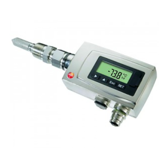
De-pressurized tube required during installation. • testo 6781 with N1/2" thread Pos: 28 /TD/Produktbeschreibung/Übersicht/MUF 63xx/Auf einen Blick MUF 6781 @ 3\mod_1238165303035_79.doc @ 30317 @ 3 4.2.2. At a glance 1 Display (optional) 2 Keys (only with optional display) 3 Test contacts 4 M 16 x 1.5 screw connection,... -
Page 16: Display And Keypad
4 Transmitter Pos: 29 /TD/Produktbeschreibung/Übersicht/MUF 63xx/Display und Tastatur 6781 @ 4\mod_1250064749770_79.doc @ 47423 @ 3 4.2.3. Display and keypad The display option allows operation of the testo 6781 transmitter via the display and four keys. The LCD display consists of one 7-segment line for displaying readings and units and of an information line (for status messages, for example). -
Page 17: Commissioning
With the alarm definition, however, the physical measuring range limits are decisive. Pos: 35 /TD/Überschriften/MUF/1.3/2.3 Inbetriebnahme @ 3\mod_1234258805768_79.doc @ 24027 @ 2 4.3. Commissioning Pos: 36 /TD/Erste Schritte/MUF 63xx/Mechanische Montage 6781 @ 3\mod_1239807163104_79.doc @ 31204 @ 3444 4.3.1. Mechanical assembly • Carefully perform assembly work. -
Page 18: Without Stainless Steel Measurement Chamber And Cooling Coil
With stainless steel • Process temperatures 0 to 50 °C measurement chamber • Fast assembly/dismantling of the testo 6781 required and/or • No sufficient inflow of the sensor (1 l/min.) exists With stainless steel • Process temperatures 50 to 200 °C... -
Page 19: With Stainless Steel Measurement Chamber (Max. 35,000 Hpa)
2. Remove measurement chamber from quick-release compressed-air fastener. 3. Screw process connection (G1/2) of the testo 6781 transmitter into the thread of the measurement chamber. 4. Mount 6781 as described under Without stainless steel measurement chamber and cooling coil page 18. -
Page 20: Connecting Voltage Supply And Analog Outputs
4 Transmitter Pos: 37 /TD/Erste Schritte/MUF 63xx/Spannungsversorgung/Analogausgänge anschließen 6781 @ 3\mod_1239951683334_79.doc @ 31673 @ 45 4.3.1.4. Connecting voltage supply and analog outputs Wiring diagram for 4-wire system (0 to 20 mA/4 to 20 mA/0 to 1 V/0 to 5 V/0 to 10 V) -
Page 21: Plug-In Connection For Power Supply And Channel
- Ch1 Pos: 39 /TD/Überschriften/MUF/1.3.3 Gerät abgleichen @ 3\mod_1236081099337_79.doc @ 27173 @ 3 4.3.2. Adjusting the instrument Pos: 40 /TD/Erste Schritte/MUF 63xx/1-Punkt-Abgleich 6781 @ 3\mod_1239794807174_79.doc @ 31163 @ 44 4.3.2.1. Self-adjustment Conventional trace humidity sensors show a steep rise in measuring uncertainty at low humidities. -
Page 22: 1-Point Adjustment By Entering A Reference Value
(working range) ✓ A reference measuring instrument (e.g. dewpoint mirror hygrometer) is ready. 1. Expose the reference measuring instrument and testo 6781 to the same constant conditions and wait for the equalization period to expire. The ideal accuracy is reached when at least two adjustment cycles are run through at dewpoint temperatures above -60 °C... -
Page 23: Analog Output Adjustment
✓ Load of max. 500 Ω is connected to channel 1 (see Plug-in connection for power supply and channel page 21) ✓ A precise multimeter (minimum requirement: resolution 6.5 digits, at least 5-times more accurate than the 6781) is available. If only a simple multimeter is available, the analog outputs may not be adjusted. -
Page 24: Operation
If the password protection is not to be used, the numerical code "0000" must be entered. This is also the status upon delivery. Pos: 45 /TD/Produkt verwenden/MUF 63xx/Aufbau des Bedienmenüs 6781 @ 3\mod_1239692809877_79.doc @ 31123 @ 3 4.4.3. Structure of user menu At the main menu level, the user menu comprises the following: •... - Page 25 4 Transmitter 1 Display for messages 2 Channel 1 display Four keys enable the user to navigate/scroll through the menus and enter/amend values and settings: Function/description • In Measuring Mode: changes to parameterization • In Parameterizing Mode: confirms a selection or setting •...
-
Page 26: Overview Of The Testo 6781 User Menu
4 Transmitter Pos: 46 /TD/Produkt verwenden/MUF 63xx/Übersicht Bedienmenü @ 3\mod_1234510821302_79.doc @ 25303 @ 3 4.4.4. Overview of the testo 6781 user menu... - Page 27 4 Transmitter...
-
Page 28: The Individual Main Menus
(1 = no delay; 15 = longest delay) Edit/select parameter with , confirm with or abort entry with ESC. 2. Continue to the main menu with or return to Measuring Mode with ESC. Pos: 48 /TD/Produkt verwenden/MUF 63xx/Hauptmenü Alarm bearbeiten 6781 @ 4\mod_1244645622570_79.doc @ 44953 @ 455... -
Page 29: Editing Main Menu Alarm
4 Transmitter 4.4.5.2. Editing Main Menu Alarm The alarm statuses are shown on the display. You can choose whether the alarm is to be used to monitor limit values or as a collective alarm. If an alarm is to be used to monitor limit values, you can choose between monitoring the minimum or maximum value and set a limit value and hysteresis for each alarm. -
Page 30: Editing Main Menu Settings
Main Menu Settings with or return to Measuring Mode with ESC. Pos: 49 /TD/Produkt verwenden/MUF 63xx/Hauptmenü Einstellungen bearbeiten 6781 @ 4\mod_1244535897708_79.doc @ 44917 @ 45555 4.4.5.3. Editing Main Menu Settings You can edit instrument settings and other settings. > In Measuring Mode, press SET, select... - Page 31 4 Transmitter Editing display settings You can set the brightness and contrast of the display. 1. Select Display Settings with and confirm selection with SET. 2. Select Backlight Contrast with and confirm selection with SET. One of the following parameters can now be selected using , after which the selection must be confirmed with SET: •...
-
Page 32: Editing Main Menu Analysis
9. Return to Main Menu Settings by pressing three times. Pos: 50 /TD/Produkt verwenden/MUF 63xx/Hauptmenü Analyse bearbeiten 6781 @ 3\mod_1241425854399_79.doc @ 32344 @ 455 4.4.5.4. Editing Main Menu Analysis You can check the function of analog outputs. In addition, you can read off the minimum and maximum values (since the last voltage supply or reset of the min./max. - Page 33 1. Read off the min./max. values of the channel in succession with and return to the Main Menu Analysis with ESC. 2. Continue to Main Menu Message with or return to Measuring Mode with ESC. Pos: 51 /TD/Produkt verwenden/MUF 63xx/Hauptmenü Meldungen bearbeiten 6781 @ 3\mod_1240905240318_79.doc @ 32203 @ 4...
-
Page 34: Editing Message Main Menu
4 Transmitter 4.4.5.5. Editing Message main menu Messages can be confirmed/acknowledged, the last messages can be called up and the display of the messages can be switched on or off. 1 Message text 2 Additional information on the message 3 Message number (example: "4/7"... -
Page 35: Calling Up Main Menu Ident
Measuring Mode with ESC. An overview of the messages can be found in Status, warning and error messages page 37 Pos: 52 /TD/Produkt verwenden/MUF 63xx/Hauptmenü Ident abfragen 6781 @ 3\mod_1239269378840_79.doc @ 31053 @ 4 4.4.5.6. Calling up Main Menu Ident... - Page 36 4 Transmitter 3. Press SET, edit value: Scroll one digit to the right using increase value of digit by 1 using . Confirm with or abort entry with ESC. 4. Continue to Analog Adj. Ch. 1 with 5. Continue with the adjustment of the analog outputs (see below, step 2) or press to return to Main Menu...
-
Page 37: Editing Reset Main Menu
Warning messages • Error messages in each case for the testo 6781 transmitter. All messages are stored in the transmitter with an operating hours stamp. Use the user menu (see Editing Message main menu page 34) or the P2A software (see Transmitter history page 63) to view the message history. -
Page 38: Status Messages
4 Transmitter 4.5.1. Status messages Status messages show the current operating status of the testo 6781. Message Display Description 02506 Sensor Message appears while the initialization transmitter is starting up. If the message disappears, the transmitter is ready for operation. -
Page 39: Warning Messages
Depending on the parameterization of the parameterization of the alarm. alarm. Depending on the Depending on the 0081F Alarm 4 parameterization of the parameterization of the alarm. alarm. Pos: 59 /TD/Produkt verwenden/MUF 63xx/Status-Warnmeldungen/Fehlermeldungen Messumformer 635x/6781 @ 3\mod_1236081613819_79.doc @ 27212 @ 3... -
Page 40: Transmitter Error Messages
Cause Remedying of fault 01505 Watchdog error Due to a processor If the problem occurs error, the transmitter frequently, contact performs an automatic Testo Service. restart. Low adjustment The ambient Take necessary 01115 temperature temperature is too low measures to raise... -
Page 41: Maintenance And Cleaning
Pos: 61 /TD/Überschriften/MUF/1.6 Wartung und Reinigung @ 3\mod_1234443039129_79.doc @ 24982 @ 2 4.6. Maintenance and cleaning Pos: 62 /TD/Produkt instand halten/MUF 63xx/Gerät warten/reinigen 6781 @ 4\mod_1244646493414_79.doc @ 44985 @ 33 4.6.1. Maintaining the instrument We recommend that the adjustment and settings of the transmitter be checked at regular intervals using the •... -
Page 42: Parameterizing, Adjusting And Analyzing Software (P2A Software)
Generally, all newer testo transmitters (as of 2007) are supported. • Included with every testo transmitter that is bought new is a CD that contains a free upgrade of the software, which includes the device drivers for all transmitters that can be attached at this time. -
Page 43: Functions And Use
5 Parameterizing, adjusting and analyzing software (P2A software) 5.1.1. Functions and use In the P2A software, two different file types are used: The instrument and the parameter file. Instrument file The parameters of a particular transmitter are stored in its so-called instrument file. -
Page 44: Scope Of Delivery
5 Parameterizing, adjusting and analyzing software (P2A software) • At least Internet Explorer 5.0. Software The P2A software must be purchased and installed separately from the transmitter. If it is a new software version, the transmitter is already supported completely. Older P2A software versions can be updated via the P2A software upgrade (cf. -
Page 45: P2A Software Upgrade
5.2.2. Starting the software 5.2.2.1. Starting the program > Select: [Start] > All Programs > Testo > P2A Software. The program window is opened (see User interface page 46). 5.2.2.2. Establishing a connection with the instrument Multiple instruments can be attached, however only one connection is active at all times. -
Page 46: Using The Software
5 Parameterizing, adjusting and analyzing software (P2A software) Pos: 72 /TD/Überschriften/MUF/3.3 Software verwenden @ 3\mod_1234258679599_79.doc @ 23989 @ 2 5.3. Using the software Pos: 73 /TD/Produkt verwenden/MUF 63xx/P2A/Software verwenden @ 3\mod_1234262654547_79.doc @ 24162 @ 3 5.3.1. User interface 1 Menu bar: Menu Command Explanation... - Page 47 5 Parameterizing, adjusting and analyzing software (P2A software) Menu Command Explanation Check instrument Checks the connections to a connections connected instrument without the instrument having to be activated. Service A text file with the most important information on the computer and the software is opened via Display service data.
-
Page 48: Editing Instrument/Parameter File
5 Parameterizing, adjusting and analyzing software (P2A software) 4 Function buttons: Dialogues on editing and testing the instrument are opened by means of the buttons. [Change parameterization] see Changing instrument/parameter file page 48 [Test/analyze transmitter] see Chapter Analyzing/testing the transmitter page 57 [Adjusting the transmitter] see Chapter Adjusting the transmitter page 60... - Page 49 5 Parameterizing, adjusting and analyzing software (P2A software) Field Explanation Unit/ All analog outputs are parameterized in this mask. Analog output Unit/analog output Unit: 0 to 1 V/5 V/10 V or 0...20 mA, 4 to 20 (graphic) Vertical: Current version of the analog output (cannot be changed).
- Page 50 The delay of the signal in relation to the change in the process is also significantly influenced by the selection of the particle filter. Pos: 76 /TD/Produkt verwenden/MUF 63xx/P2A/Grenzwerte Relais 6781 @ 4\mod_1250579466639_79.doc @ 47463 @ Field Explanation Alarm values, alarm 1 to 4 In this mask, the display alarms are parameterized.
- Page 51 5 Parameterizing, adjusting and analyzing software (P2A software) Field Explanation Collective alarm If selected messages appear, a collective alarm can be triggered. Selection of the messages (OR linkage) by selecting the checkbox. If switched to ON (NO contact) or Min control OFF (NC contact) under the limit value;...
- Page 52 (0 to 240 seconds possible). The response delay has no effect on the collective alarms. Pos: 77 /TD/Produkt verwenden/MUF 63xx/P2A/Grundeinstellungen 6781 @ 4\mod_1244205730179_79.doc @ 44535 @ Field Explanation Basic settings Setting the absolute pressure.
- Page 53 5 Parameterizing, adjusting and analyzing software (P2A software) Field Explanation Absolute pressure The absolute pressure is included in the calculation of the following units: • °C or °F • g/kg or gr/lb • ppm (vol) Pos: 78 /TD/Produkt verwenden/MUF 63xx/P2A/Display @ 3\mod_1234424330866_79.doc @ 24673 @ Field Explanation Display...
- Page 54 "0000" must be entered. [Adopt new Button for confirming the new password. password] Valid password Display of the current password. Pos: 79 /TD/Produkt verwenden/MUF 63xx/P2A/Selbstabgleich 6781 @ 4\mod_1244444184402_79.doc @ 44673 @ 5 Field Explanation Self-adjustment Setting the self-adjustment. Activate self- •...
-
Page 55: Creating A New Instrument File
• 12 hours • 24 hours In order to receive reliable readings during the calibration or equalization period of the transmitter, testo recommends the shortest possible cycle time. A longer cycle time can be set in continuous operation. Start self-... -
Page 56: Opening The Parameter File
5 Parameterizing, adjusting and analyzing software (P2A software) The original name (Instrument type, Serial number) is suggested with the current date/time as standard, e.g. "testo 6781 01234578 061120 1403.cfp". For a standard installation, the files are saved under "C:\Documents and Settings\All Users\Shared Documents\P2A Software". -
Page 57: Deleting Instrument/Parameter File
5 Parameterizing, adjusting and analyzing software (P2A software) Pos: 84 /TD/Produkt verwenden/MUF 63xx/P2A/Geräte-/Parameterdatei löschen @ 3\mod_1234359025194_79.doc @ 24379 @ 4 5.3.2.6. Deleting instrument/parameter file Instrument/parameter files can be deleted from the file list. 1. Click on the file that is to be deleted with the right mouse button. 2. -
Page 58: Testing Analog Output
5 Parameterizing, adjusting and analyzing software (P2A software) Current operating hours are shown. 3. Confirm control query to perform the reset. The values are reset to the customer-specific factory settings. 4. Click on [OK] [Cancel] to close the dialogue. Pos: 88 /TD/Produkt verwenden/MUF 63xx/P2A/Analogausgang testen _6781 @ 3\mod_1241448537872_79.doc @ 32540 @ 4 5.3.3.3. -
Page 59: Displaying Min./Max. Values
5 Parameterizing, adjusting and analyzing software (P2A software) Field/button Explanation [Activate] The entered default value is forwarded to the corresponding analog output and to the test contacts by clicking. A warning informs that the value is being transmitted to the connected instrument in the event of existing cabling. -
Page 60: Adjusting The Transmitter
Pos: 90 /TD/Überschriften/MUF/x.x.x Messumformer abgleichen @ 4\mod_1244530152797_79.doc @ 44885 @ 3 5.3.4. Adjusting the transmitter Pos: 91 /TD/Produkt verwenden/MUF 63xx/P2A/Messumformer abgleichen 6781 @ 3\mod_1241447656216_79.doc @ 32519 @ This function is used to adjust an attached instrument. The following adjustments may be carried out using the software: •... -
Page 61: 1-Point Adjustment
5 Parameterizing, adjusting and analyzing software (P2A software) 5.3.4.1. 1-point adjustment A dew mirror hygrometer is recommended as the reference measuring instrument for the 1-point adjustment (offset). 1. Expose the reference measuring instrument and the instrument to be adjusted to the same constant conditions and wait for equalization period to lapse. -
Page 62: Adjusting The Analog Output
5 Parameterizing, adjusting and analyzing software (P2A software) Field Explanation Reference value Entry of the read-off value from the reference measuring instrument. Permissible entries: • max. 10 °C deviation (sum of all 1-point adjustments) • max. 2 K (°C) deviation (sum of all 1-point adjustments) >... -
Page 63: Transmitter History
Pos: 94 /TD/Überschriften/MUF/2.3.5 Messumformer-Historie @ 3\mod_1237373806926_79.doc @ 29846 @ 3 5.3.5. Transmitter history Pos: 95 /TD/Produkt verwenden/MUF 63xx/P2A/Messumformer-Historie 6781 @ 4\mod_1244209291490_79.doc @ 44567 @ Parameterizations, adjustment processes and messages that have occurred are registered in the transmitter with an operating hours stamp. - Page 64 5 Parameterizing, adjusting and analyzing software (P2A software) For parameter changes or adjustments that are performed directly at the instrument (via the user menu), "Transmitter" is entered in the User field and only the operating hour is entered in the Date/time field instead of operating hour/date/time.
- Page 65 5 Parameterizing, adjusting and analyzing software (P2A software) Field Explanation Selection of adjustment histories: 1-point adjustments Analog adjustments. Operating hours / Operating hour/time stamp at which the date/time change at the instrument was performed. User Name with which the user is logged into the operating system.
- Page 66 5 Parameterizing, adjusting and analyzing software (P2A software) Field Explanation Offset Analog adjustment: Deviation at time of adjustment. The table is shown only for error and status messages that were generated in the transmitter and were transferred and saved there via the connection to the P2A software.
- Page 67 Tips and assistance Pos: 97 /TD/Überschriften/8.1 Fragen und Antworten @ 0\mod_1177402017078_79.doc @ 1093 @ 2 6.1. Questions and answers Pos: 98 /TD/Tipps und Hilfe/Fragen und Antworten/MUF 6781 @ 3\mod_1239863529560_79.doc @ 31233 @ Question Possible causes/solution Connection to instrument Check connection cable/plug contacts...
- Page 68 Hose PTFE tube with compressed air connections, 0699 2824/4 2 m, up to 140 °C and max. 9000 hPa External display Process display for testo 54-2 AC..5400 7553 Process display for testo 54-7 AC..5400 7555 Calibration Standard ISO calibration certificate for...
- Page 69 6 Tips and assistance Pos: 101 /TD/Tipps und Hilfe/Zubehör und Ersatzteile/MUF63xx/Bestelloptionen MUF 6781 @ 3\mod_1239270048266_79.doc @ 31074 @ 3 6.2.1. Ordering options for testo 6781 transmitter (0555 6781) Order code Characteristic Axx Process connection Process connection G1/2 Process connection NPT 1/2"...
- Page 70 6 Tips and assistance Order code Characteristic gr/ft /Min/Max g/kg /Min/Max gr/lb /Min/Max Kxx Languages of instruction manual German/English instruction manual French/English instruction manual Spanish/English instruction manual Italian/English instruction manual Dutch/English instruction manual Japanese/English instruction manual Chinese/English instruction manual Swedish/English instruction manual Mxx Protection cap Protection cap made of stainless steel Protection cap made of PTFE...
- Page 72 0970 6781 en 01 V1.0 V01.40-1 en...
Need help?
Do you have a question about the 6781 and is the answer not in the manual?
Questions and answers