Advertisement
© Panduit Corp. 2010
Contents:
1 - ENCLOSURE
4 - #12-24 X 1/2" SCREWS
2 - #10-32 X 3/8" SCREWS
4 - #10-32 HEX NUTS
CAUTION:
Fiber optic cable is sensitive to excessive pulling, bending and crushing forces. Consult the manufacturer's cable specification sheet for the
specific cable in use.
Follow TIA/EIA-568A, 569, 606, and 607 installation guidelines where applicable.
WARNING: UNMATED CONNECTORS MAY EMIT INVISIBLE LASER RADIATION. DO NOT LOOK DIRECTLY INTO THE END OF
THE CONNECTOR. DO NOT INSPECT WITH MAGNIFYING DEVICES. MAINTAIN CAP ON UNMATED CONNECTORS.
Care should be taken when opening and closing fully loaded enclosure in order to protect fiber components.
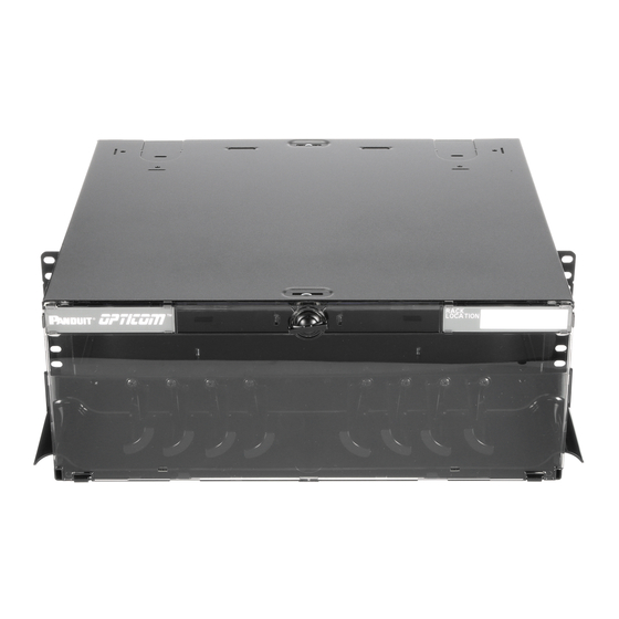
ASSEMBLY VIEW
Lid (not removable)
Bend Radius
Post
Blank
(removable)
For Technical Support: www.panduit.com/resources/install_maintain.asp
Opticom Rack Mount Fiber Cassette Enclosure
INSTALLATION INSTRUCTIONS
3 - TAK-TYS (6" pcs.)
4 - CABLE TIES (PLT2S-M0)
Enclosure
Sliding Drawer
Page 1 of 10
Part Number: FCE4U
FCE4U
3 - ADHESIVE BEVEL ENTRY CLIPS
1 - CAUTION LABEL
1 - LASER WARNING LABEL
Door Assembly
(shown in open
position)
FS012
Trunk or
Interconnect
Cable Entry
Grommet
Strain Relief Bracket
Enclosure
Figure 1
Advertisement
Table of Contents

Related Manuals for Panduit FCE4U


Summary of Contents for Panduit FCE4U
-
Page 1: Table Of Contents
Opticom Rack Mount Fiber Cassette Enclosure Part Number: FCE4U INSTALLATION INSTRUCTIONS FS012 © Panduit Corp. 2010 FCE4U Contents: 1 - ENCLOSURE 2 - GROMMETS 3 - ADHESIVE BEVEL ENTRY CLIPS 4 - #12-24 X 1/2" SCREWS 2 - STRAIN RELIEF BRACKETS... -
Page 2: M6X1 Screws
INSTALLATION INSTRUCTIONS FS012 © Panduit Corp. 2010 PREPARATION AND RACK MOUNTING Install the bend radius posts on each side as shown. Determine where the cable will enter the enclosure. Bend Radius Carefully remove the knock-out at that entry location Post of the fiber tray making sure not to damage the surrounding sheet metal. -
Page 3: Grommets
INSTALLATION INSTRUCTIONS FS012 © Panduit Corp. 2010 After the enclosure is mounted in the rack, determine the size of the innerduct that will be used to bring the cable into the enclosure. Install grommet following the proper cutting diagram (See Figure 4A). - Page 4 INSTALLATION INSTRUCTIONS FS012 © Panduit Corp. 2010 Opticom QuickNet Cassette Installation Cassette Installation Option Cassettes (12 capacity) Insert Opticom QuickNet Pre-Terminated Fiber Optic Cassettes into the enclosure as shown. Once mounted, fully seat NyLatches to secure the cassette. Fully extend tray to ensure proper amount of slack is used.
- Page 5 INSTALLATION INSTRUCTIONS FS012 © Panduit Corp. 2010 Tray in home position. (cover omitted for clarity) Figure 6C For Technical Support: www.panduit.com/resources/install_maintain.asp Page 5 of 10...
-
Page 6: Slack Spools
INSTALLATION INSTRUCTIONS FS012 © Panduit Corp. 2010 Field-Terminated Trunk Option FAPs (12 capacity) Place slack spools over #10-32 studs on sliding Slack tray. Secure with #10-32 hex nuts or adhesive Spools mounts (make sure to punch hole into adhesive mounts). Note spool orientation. -
Page 7: Adhesive Mounts
INSTALLATION INSTRUCTIONS FS012 © Panduit Corp. 2010 Tak-Ty Grommet cables to Route fiber through grommet as shown. fence or Use enough cable length to ensure one cover as complete loop of individual fibers around needed. “A” slack spools. Leave enough jacketed slack... - Page 8 INSTALLATION INSTRUCTIONS FS012 © Panduit Corp. 2010 FOSM Fiber Optic Splice Module Installation FOSM (12) Place FOSM Holder over #10-32 studs on capacity sliding tray (note orientation). Secure with #10-32 hex nut. Place first FOSM on top of FOSM Holder (note orientation). The...
- Page 9 INSTALLATION INSTRUCTIONS FS012 © Panduit Corp. 2010 Tak-Ty cable to Grommet fence or cover Route fiber through grommet as shown. Use enough cable length to ensure one complete Fixed Tak-Ty loop of individual fibers around splice tray slack spools. (See instruction sheet for splice trays).
-
Page 10: Bend Radius Posts
INSTALLATION INSTRUCTIONS FS012 © Panduit Corp. 2010 Re-install front and rear door assemblies if removed during fiber installation. Attach Laser Warning Label and Caution Label where they are clearly visible. Figure 9 Rotate the Bend Radius Posts to the open...
Need help?
Do you have a question about the FCE4U and is the answer not in the manual?
Questions and answers