Table of Contents

Related Manuals for Panduit ZDF48-RA


Summary of Contents for Panduit ZDF48-RA
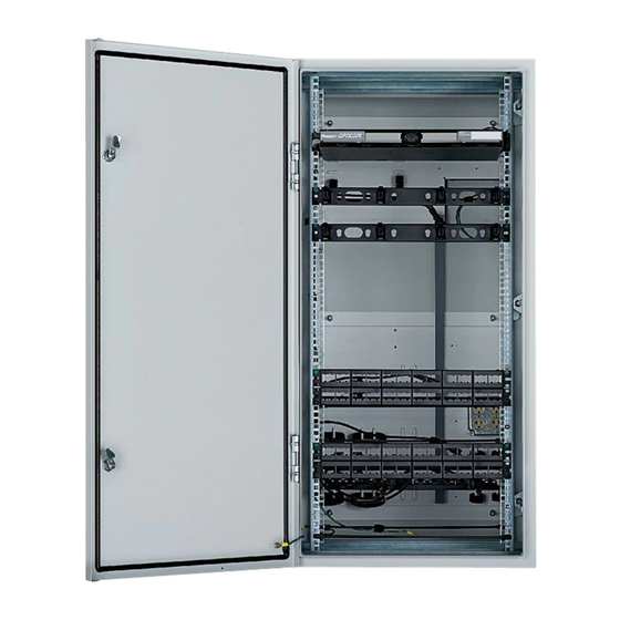
- Page 1 Panduit PreConfigured Industrial Distribution Frame (IDF) Installation Instructions Part Numbers ZDF48-RA and ZDF48-EA Figure 1: Industrial Distribution Frame (IDF) Equipment Elevation www.panduit.com V00028CA Rev03 Page 1 of 18...
-
Page 2: Table Of Contents
IDF Unpacking ..................................2 IDF Switch Deployment Guide ............................4 IDF Preparation and Mounting ............................7 ZDF48-RA - Power Installation ............................8 ZDF48-EA - Power Installation ............................8 Copper Trunk Cable Installation ............................ 11 Fiber Trunk Cable Installation ............................12 UPS Installation ................................. - Page 3 IDF Enclosure Labels and Covers Instructions Enclosure Mounting Hardware Fiber Enclosure Kit and Instructions Tak-Ty Common Bonding Network (CBN) Jumper Kit Electrostatic Discharge (ESD) Wrist Strap Kit Figure 3: Contents of the miscellaneous cartons. www.panduit.com V00028CA Rev03 Page 3 of 18...
-
Page 4: Idf Switch Deployment Guide
Prior to routing power cable and horizontal communication cables, the switch placement inside the enclosure must be considered for a successful deployment. This document is intended to provide system integrators and field installers with Panduit’s recommendations regarding switch deployment within Panduit’s Industrial Distribution Frame (IDF). The IDF is currently... - Page 5 25.5 13.31 24.9 Handle may interfere with patch field Handle may interfere with patch field. Limited by Center Section and Wall 13.31 Section flange Table 1: Useable depth of the enclosure per RU www.panduit.com V00028CA Rev03 Page 5 of 18...
- Page 6 Figure 4: IDF Section showing the useable depth of the enclosure. www.panduit.com V00028CA Rev03 Page 6 of 18...
-
Page 7: Idf Preparation And Mounting
8. Following the Hoffman installation guide, mount the enclosure in the desired location using the 6 holes on the wall section of the enclosure. 9. Install all conduit connections in the appropriate locations. www.panduit.com V00028CA Rev03 Page 7 of 18... -
Page 8: Zdf48-Ra - Power Installation
ZDF48-RA - Power Installation 10. Remove the outlet box cover with the (2) 20 amp power outlets. Figure 7: Outlet Box and Cover 11. Punch out the center knockout of the outlet box. 12. Pull the plant power through the conduit into the outlet box and terminate the power and ground according to local IEC code. - Page 9 Figure 8: Fiber Switch A and B Tak-Ty to Rear Rail Figure 9: Fiber Power Cables A and B. View looking from the rear of the enclosure. Arrows indicate Tak-Ty locations. www.panduit.com V00028CA Rev03 Page 9 of 18...
- Page 10 Figure 9.Error! Reference source not ound. The aqua arrows show the Tak-Ty locations. Figure 10: Copper Power Cables A and B. View looking from the rear of the enclosure. Arrows indicate Tak-Ty locations. www.panduit.com V00028CA Rev03 Page 10 of 18...
-
Page 11: Copper Trunk Cable Installation
Backplane. 78” of slack (measured from enclosure bottom) is required in the enclosure. This leaves enough cable to terminate onto the copper jacks. Figure 12: Copper Cable Routing showing Switch-A on the left and Switch-B cables on the right. www.panduit.com V00028CA Rev03 Page 11 of 18... -
Page 12: Fiber Trunk Cable Installation
Cut the armored cable for 155 inches inside the enclosure. Leaving a stub of bare armor above the conduit. b. Optional: Utilize Panduit’s Armored Cable Grounding Jumper Kit (ACG24K, ACG24K-500, ACG24KX-500) to ground the armor of the cable. www.panduit.com... - Page 13 36. Route the jacketed fiber cable up through the Panduit Duct and through the supplied Tak-Ty indicated on the Upper Backplane as shown in Figure Figure 14: Fiber Trunk routing on Upper Backplane 37. Route the jacketed cable through the loom tubing supplied in the miscellaneous kit. The tubing protects the fiber from getting pinched in the hinge.
- Page 14 Insert the fiber connectors into the desired pre-installed fiber adapter panel (FAP) locations in the enclosure. Note that the FAPs can be easily removed via push pull latches on the faceplates. Figure 17: FRME1U Fiber Enclosure Cable Routing www.panduit.com V00028CA Rev03 Page 14 of 18...
-
Page 15: Ups Installation
Plug into the outlet box on the Lower Backplane. e. Use the Tak-Ty provided on the Backplane to retain the AC power Cord. Copper Switch A&B Installation. 44. Reference the Cisco Installation Instructions provided with the switches. www.panduit.com V00028CA Rev03 Page 15 of 18... - Page 16 Figure 19: Location of horizontal support bars on rear of IDF. 46. Connect the switch to the patch panel in RUs 5 and 6. Panduit recommends using part number UTP28SP8INBU- 48, Cat6 UTP 28AWG CM/LSZH Cable Assembly, Blue, 8 Inch, Bulk Package of 48 (ordered separately). The 8- inch length allows for connection from switch port to patch panel without extra length that would require cable management.
-
Page 17: Fiber Switch A&B Installation
RU21, Panduit recommends using part number FX2ERLNLNSNM001, 2-fiber OM3 1.6mm Jacket Patch Cord LSZH LC Duplex to LC Duplex Std IL – 1M. The cable should be routed through the Panduit CMPHF1 Horizontal Cable Manger in RU 18. Refer to... - Page 18 58. Attach the Fiber Switch-A AC cable to the UPS. The plug is Tak-Ty just above the UPS. The cords are shown in Figure 59. Complete the installation and setup per the switch installation instructions. 60. Repeat steps 53 through 59 for Fiber Switch-B in RU 21. www.panduit.com V00028CA Rev03 Page 18 of 18...
Need help?
Do you have a question about the ZDF48-RA and is the answer not in the manual?
Questions and answers