Advertisement
© Panduit Corp. 2011
FRME1
Assembly Instructions
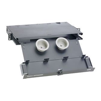
Determine the cable entry location on the enclosure.
Remove the knockout by inserting a screwdriver into the slot
located in the center of the knockout and apply a twisting
downward motion then lift out. Insert grommet following proper
cutting diagram. Grounding Lug attaches to a stud at the rear,
inside the enclosure on the top or bottom with a #10-32 nut.
Apply Laser Warning Label and Caution Label in a clearly visible
location. Apply Port I.D. Label(s) on the inside of the tray.
Port I.D. Label
For Technical Support: www.panduit.com/resources/install_maintain.asp
Opticom Fiber Optic Rack Mount Enclosure
INSTALLATION INSTRUCTIONS
Fiber Laser
Warning Label
Fiber Caution
Label
Spool
Part Number: FRME1
Contents:
(1) FRME Enclosure
(1) Port I.D. Label
(2) EIA Enclosure Brackets
(1) FRME Kit
GROMMET CUTTING DIAGRAM
Cut the small
circle for 1"
diameter
innerduct
Grounding Lug
Page 1 of 2
FRME Kit Contents:
(1) Grounding Lug
(2) Cable Ties
(1) #10-32 x 3/8" Screw
(1) #10-32 x 1/4" Screw
(4) #12-24 x 1/2" Screws
(4) M6 x 1.0 x 15MM Screws
(1) Fiber Caution Label
(1) Fiber Laser Warning Label
(2) Grommets
(2) #10-32 Hex Nuts
(1) Strain Relief Clip
Cut the large
Cut the straight
circle for 1-1/2"
lines when not
diameter
using any
innerduct
innerduct
Grommet
Bracket
FS024
Advertisement
Table of Contents

Related Manuals for Panduit FRME1


Summary of Contents for Panduit FRME1
- Page 1 Opticom Fiber Optic Rack Mount Enclosure Part Number: FRME1 INSTALLATION INSTRUCTIONS FS024 © Panduit Corp. 2011 Contents: FRME Kit Contents: (1) FRME Enclosure (1) Grounding Lug (1) Port I.D. Label (2) Cable Ties (2) EIA Enclosure Brackets (1) #10-32 x 3/8" Screw (1) FRME Kit (1) #10-32 x 1/4"...
- Page 2 INSTALLATION INSTRUCTIONS FS024 © Panduit Corp. 2011 Attach Strain Relief Clip with the #10-32 screw and nut provided. Bracket orientation for projection Bracket orientation for 23 inch rack mount on a 19 inch rack Locate rack bracket on the mid...
Need help?
Do you have a question about the FRME1 and is the answer not in the manual?
Questions and answers