Advertisement
Quick Links
© Panduit Corp. 2008
FCE1U
Contents
2 (3) T
-T
Tape (6" pcs.)
AK
Y
2 SLACK SPOOLS
1 (2) #10-32 x 3/8" SCREW
3 (4) #10-32 HEX NUTS
WARNING: UNMATED CONNECTORS MAY EMIT INVISIBLE LASER RADIATION. DO NOT LOOK DIRECTLY INTO THE END OF THE
CONNECTOR. DO NOT INSPECT WITH MAGNIFYING DEVICES. MAINTAIN DUST CAPS ON UNMATED CONNECTORS.
CAUTION:
Fiber optic cable is sensitive to excessive pulling, bending, and crushing forces. Consult the manufacturer's cable specification sheet for the
specific cable in use.
Follow TIA/EIA-568-A, 569, 606, and 607 installation guidelines where applicable.
Care should be taken when opening or closing a fully loaded drawer in order to protect the fiber components.
ASSEMBLY VIEW
Cover (field removable)
Fiber Adapter Panels (FAPs):
Up to 4 for FCE1U, FCE1UA.
Up to 8 for FCE2U.
Bend Radius
Control Clip
Door Assembly
(shown in open
position)
FOR TECHNICAL SUPPORT www.panduit.com/resources/install_maintain.asp
O
PTICOM
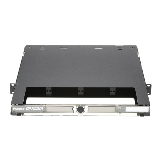
Part Numbers: FCE1U, FCE1UA, FCE2U
INSTALLATION INSTRUCTIONS FS006
1 (2) FIBER GROMMETS
4 #M6 x 1 SCREWS
1 (2) STRAIN RELIEF BRACKET
4 CABLE TIES (PLT2S-M0)
2 (4) BEND RADIUS CLIPS
O
Fiber Adapter Panel (FAP) Installation (FAPs not included).
PTICOM
Q
N
Rack Mount Fiber Cassette Enclosures
UICK
ET
FCE1UA
Plunger and
Grommet
Page 1 of 11
(FCE2U)
4 #12-24 x 1/2" SCREWS
1 LASER WARNING LABEL
3 BEVELED ENTRY CLIPS
Strain Relief
Bracket
Enclosure
Enclosure Sliding Drawer
Trunk or Interconnect
Cable Entry Grommet
Figure 1
Advertisement

Subscribe to Our Youtube Channel
Related Manuals for Panduit FCE1U


Summary of Contents for Panduit FCE1U
- Page 1 Care should be taken when opening or closing a fully loaded drawer in order to protect the fiber components. ASSEMBLY VIEW Fiber Adapter Panel (FAP) Installation (FAPs not included). PTICOM Cover (field removable) Fiber Adapter Panels (FAPs): Up to 4 for FCE1U, FCE1UA. Trunk or Interconnect Up to 8 for FCE2U. Cable Entry Grommet Bend Radius Strain Relief...
-
Page 2: Enclosure
(4) #12-24 x 12" screws. Use (4) M6 x 1 screws if mounting to a metric rack. Use (2) #12-24 X 1/2" screws (provided). Repeat for other side. Figure 4A For Technical Support: www.panduit.com/resources/install_maintain.asp Page 2 of 11... - Page 3 Place the strain relief bracket adjacent to the knocked out enclosure entry point. Fasten with #10-32 x 3/8" screw and hex nut. #10-32 Hex Figure 6 Note: Cover not shown for clarity. For Technical Support: www.panduit.com/resources/install_maintain.asp Page 3 of 11...
- Page 4 Up to 8 for FCE2U. Figure 7 Fully extend drawer to ensure proper amount of slack is used. Isometric view showing drawer fully extended and tilted down (cables omitted for clarity). Figure 7A For Technical Support: www.panduit.com/resources/install_maintain.asp Page 4 of 11...
- Page 5 Adhesive Bevel Entry Clips. Note location and position of clips. Drawer in extended position Figure 7B Figure 7C Drawer in home position For Technical Support: www.panduit.com/resources/install_maintain.asp Page 5 of 11...
-
Page 6: Adhesive Mounts
Please note orientation of spools. Figure 8 Fully extend drawer to ensure proper amount of slack is used. Isometric view showing drawer fully extended and tilted down (cables omitted for clarity). Figure 8A For Technical Support: www.panduit.com/resources/install_maintain.asp Page 6 of 11... - Page 7 [25.4m] right). Fiber Breakout Detail Be sure adhesive mount secures jacketed Trunk cable. DO NOT clip individual Figure 8B Drawer in extended position. 900µm buffered fibers. Figure 8C Drawer in home position For Technical Support: www.panduit.com/resources/install_maintain.asp Page 7 of 11...
- Page 8 #10-32 hex nuts. Remaining FOSMs are stacked on top of each other and snap in place. If 4 FOSMs are to be installed in the FCE1U or FCE1UA, side latches on top module must be broken off to close enclosure drawer.
- Page 9 Use T Tape to secure fiber cords at Detail on cable entry location and other points as page 7). shown. Drawer in extended position Figure 9B Drawer in home position Figure 9C For Technical Support: www.panduit.com/resources/install_maintain.asp Page 9 of 11...
-
Page 10: Plungers And Grommets
Bend Radius securing bend radius clip. Flange Control Clip Grommet Plunger. Figure 10A Install patch cords into FAPs/cassettes routing through bend radius control clips and maintaining proper patch cord bend radius. Figure 11 For Technical Support: www.panduit.com/resources/install_maintain.asp Page 10 of 11... -
Page 11: Caution Label
Cover and Door Re-Attachment Re-install top cover, front door and rear door assemblies, if removed during fiber installation. Attach Laser Warning Label and Caution Label where they are clearly visible. Figure 12 For Technical Support: www.panduit.com/resources/install_maintain.asp Page 11 of 11...
Need help?
Do you have a question about the FCE1U and is the answer not in the manual?
Questions and answers