Advertisement

USER INSTRUCTIONS
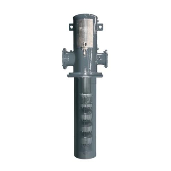
Vertical Turbine Pumps
Installation
Wet Pit (VTP)
Operation
Double Casing (VPC)
Maintenance
E, S and A series VTPs in wet pit and suction barrel designs
ranging in sizes from 50 mm (6 in.) to 1300 mm (52 in.) with
a single or multiple stages. (This manual does not cover
VTPs fitted with thrust bearing assemblies and VTPs built
for cryogenic service).
PCN=71569224 02-15(F), Based on VTP-QS-0896 Original
Instructions
These instructions must be read prior to installing,
operating, using and maintaining this equipment

Advertisement

Table of Contents
loading
Need help?

Need help?

Do you have a question about the VTP and is the answer not in the manual?

Questions and answers

Subscribe to Our Youtube Channel

Summary of Contents for Flowserve VTP

  • Page 1 (This manual does not cover VTPs fitted with thrust bearing assemblies and VTPs built for cryogenic service). PCN=71569224 02-15(F), Based on VTP-QS-0896 Original Instructions These instructions must be read prior to installing, operating, using and maintaining this equipment...
  • Page 2: Table Of Contents

    Consignment receipt and unpacking ..... 10     DRAWINGS AND PARTS LISTS ....58     Handling ............10     Cross Section: Product Lubricated VTP ..58     Lifting ............. 10     Cross Section: Enclosed Tube VTP ....61    ...
  • Page 3 Piping (4.7) .............. 31 Pre-commissioning (5.1) .......... 35 Priming and auxiliary supplies (5.6) ......41 Protection systems (4.10) ........34 Reassembly (6.10, Assembly) ......... 55 Receipt and unpacking (2.1) ........10 Recommended spares (6.4) ........499 Page 3 of 76 flowserve.com...
  • Page 4: Introduction And Safety

    Certification . (See section n 9, Certificatio on.) directly with h the produc Disclaimer Flowserve p roducts are d esigned, dev eloped and Inform mation in thes se User Instr ructions is b believed manufacture...
  • Page 5: Safety

    4 – 02-15 VERTICA AL TURBINE E PUMPS (VT TPS) CENTRI IFUGAL PUM MPS ENGLIS SH 71569224 Safet used i in potentially y explosive a atmospheres sectio on 1.6.4 also applies. 1.6.1 mmary of safe ety markings NEVE ER DO MAINT TENANCE W WORK These User I...
  • Page 6 Where e Flowserve ha as supplied o nly the bare s shaft START TH HE PUMP WIT TH OUTLET pump, the Ex rating applies only t to the pump.
  • Page 7 Preventin ng the buildu up of explosi on a maximu um ambient o of 40 ºC (104 º ºF); refer to mixture Flowserve fo or higher amb bient temperat tures. ENSURE THE E PUMP IS P PROPERLY F FILLED The surface...
  • Page 8: Safety Labels Summary

    4 – 02-15 VERTICA AL TURBINE E PUMPS (VT TPS) CENTRI IFUGAL PUM MPS ENGLIS SH 71569224 advers sely affect the e ambient con nditions. Whe ere there reventing spa arks 1.6.4.5 is a ris sk from such t tools or mater rials, mainten nance To pre...
  • Page 9: Specific Machine Performance

    4 – 02-15 VERTICA AL TURBINE E PUMPS (VT TPS) CENTRI IFUGAL PUM MPS ENGLIS SH 71569224 1.9.1 Typical ver rtical motor noise data (H Hollow The usual ap pproach is to control the ex xposure time and Solid s shafts) the noise or to enclose th...
  • Page 10: Transport And Storage

    An ny shortage an throug gh this flang or damage m must be repor rted immediat tely to Flowserve a nd received in n writing with in one month 2.3.2 Lifting of ty ype-W cast d discharge he ead with...
  • Page 11 4 – 02-15 VERTICA AL TURBINE E PUMPS (VT TPS) CENTRI IFUGAL PUM MPS ENGLIS SH 71569224 2.3.3.1 2.3.4 Lifting of b bowl assemb bly only wo point liftin ng of fabricat ted discharg Clamp p the bowl ass sembly and ce enter the liftin ng hook ead types TF,...
  • Page 12 4 – 02-15 VERTICA AL TURBINE E PUMPS (VT TPS) CENTRI IFUGAL PUM M PS ENGLIS S H 71569224 2.3.5 Lifti ng of suction n barrel Suction barre el (also referr red as ‘Can’) is always supplied sep parately and h has to be insta alled into the sump first.
  • Page 13 Therefore, before lifting is attempted, exercise caution to prevent any injuries or loss of life. Pump must be supported at least two places when lifted. Do not use chains to wrap around. Page 13 of 76 flowserve.com...
  • Page 14: Storage

    4 – 02-15 VERTICA AL TURBINE E PUMPS (VT TPS) CENTRI IFUGAL PUM MPS ENGLIS SH 71569224 person nal protective equipment is s used. The s afety Stora specifi cations must be in accord ance with the e current regulat tions at all tim mes.
  • Page 15 The VT TP configurat tions shown in n sec 3.1.1 an nd 3.1.2 are typ pical for variet ty of VTP mo dels with the bowl assem mbly types suc ch as EB, EG G, EH, EJ, EK K, EL,...
  • Page 16: Nomenclature

    L, M, H, Y… No. of Stage The typical n nomenclature above is the general guid to the VTP c configuration d description. I dentify the actual pump size and ser ial number fro om the pump nameplate.
  • Page 17: Design Of Major Parts

    Flowserve. Design of Major Part Please re efer to append dix for Europu ump part numbe er equivalents 3.3.1...
  • Page 18 4 – 02-15 VERTICA AL TURBINE E PUMPS (VT TPS) CENTRI IFUGAL PUM MPS ENGLIS SH 71569224 A shaft seali ng arrangeme ent is located d in the See se ectional draw ings supplied d with the pum mp for discharge he ead to seal th e shaft at its e...
  • Page 19 CKING GLAND UD (326A) X NUT (327A) (354) STUD 3.3.6 Impe ellers (355 5) HEX NUT VTP’s are su upplied with e enclosed, or s emi open impeller type es. Impellers are low, med dium and high capacity type e designed fo...
  • Page 20 3.3.8 chanical shaf ft seal VTP’s can al lso be fitted w with a mechan nical seal. Th he requiremen nt to fit the me echanical sea al to be provid...
  • Page 21: Performance And Operation Limits

    Special desig gns and mate erials may be available for pumps opera ating above a and below the se specified limits. Conta act Flowserve e for upgrade options Alwa ays support s shafting in at l least available for your specific c application.
  • Page 22 4 – 02-15 VERTICA AL TURBINE E PUMPS (VT TPS) CENTRI IFUGAL PUM MPS ENGLIS SH 71569224 provision of c correct found ation and ins tallation may xample of a ty ypical dischar rge head with h the lead to failur re of the pump p and, as suc ch, would be...
  • Page 23: Grouting

    4 – 02-15 VERTICA AL TURBINE E PUMPS (VT TPS) CENTRI IFUGAL PUM MPS ENGLIS SH 71569224 Examp ple of pump m mounted on a soleplate 4.3.4 Leveling o of pumps with h suction ba arrel mounted o on a soleplat The so oleplate [23] is s first lowered...
  • Page 24: Lifting And Assembly

    4 – 02-15 VERTICA AL TURBINE E PUMPS (VT TPS) CENTRI IFUGAL PUM MPS ENGLIS SH 71569224 Grouting pro ovides solid co ontact betwee en the pump Lifting and d Assembly unit and foun ndation that p prevents latera al movement Motors s may be sup plied separat...
  • Page 25 4 – 02-15 VERTICA AL TURBINE E PUMPS (VT TPS) CENTRI IFUGAL PUM MPS ENGLIS SH 71569224 For pu umps supplied d with hollow shaft drivers and a Lineshaft w when shipped d separately one-pie ece headsha ft (headshaft couples belo should be lef ft in the crate to avoid dama...
  • Page 26 4 – 02-15 VERTICA AL TURBINE E PUMPS (VT TPS) CENTRI IFUGAL PUM MPS ENGLIS SH 71569224 4.5.2.4 See section 4 4.4.4 for coup pling installatio on on solid Installing g the fully as ssembled pum If a bas se plate is use ed, level the p plate to 0.16 m mm per...
  • Page 27 4 – 02-15 VERTICA AL TURBINE E PUMPS (VT TPS) CENTRI IFUGAL PUM MPS ENGLIS SH 71569224 4.5.3 Insta allation of co ouplings on s solid shaft heck the fit of the straight ke ey and split th hrust driv ers.
  • Page 28 4 – 02-15 VERTICA AL TURBINE E PUMPS (VT TPS) CENTRI IFUGAL PUM MPS ENGLIS SH 71569224 4.5.3.2 4.5.3.3 stallation of a adjustable fl langed space Installatio on of non-ad djustable flan nged oupling WSA/ /PSA. coupling g WNA/PNA. Follow w procedure fr rom (a) thru (e e) as listed in...
  • Page 29 4 – 02-15 VERTICA AL TURBINE E PUMPS (VT TPS) CENTRI IFUGAL PUM MPS ENGLIS SH 71569224 4.5.4 Insta allation of dr rivers k) Ch heck the pack king slip to see e if a guide bu ushing is quired, if so, d determine if th he bushing is already...
  • Page 30: Initial Alignment

    4 – 02-15 VERTICA AL TURBINE E PUMPS (VT TPS) CENTRI IFUGAL PUM MPS ENGLIS SH 71569224 e) Check d river manufac cturer's instruc ctions for o line leads. To change d irection of rot tation on special in nstructions inc cluding lubrica ation two-phase mo...
  • Page 31: Piping

    4 – 02-15 VERTICA AL TURBINE E PUMPS (VT TPS) CENTRI IFUGAL PUM MPS ENGLIS SH 71569224 screws shou uld be used to o locate the m motor assembl in its final ali gned position rallel See section 5 5.3.2.1 for fina al coupling ali gnment for solid shaft.
  • Page 32 4 – 02-15 VERTICA AL TURBINE E PUMPS (VT TPS) CENTRI IFUGAL PUM MPS ENGLIS SH 71569224 b) Ne ever draw pip ing into place e by applying force to Never use e the pump as s a support fo ump flange co onnections.
  • Page 33 E PUMPS (VT TPS) CENTRI IFUGAL PUM MPS ENGLIS SH 71569224 4.7.2.1 able of maxim mum forces a and moments ts allowed on n VTP pump flanges Discharge Hea ad Size mm(in.) Head rces & Type ments (10) (12) (14)
  • Page 34: Electrical Connections

    4 – 02-15 VERTICA AL TURBINE E PUMPS (VT TPS) CENTRI IFUGAL PUM MPS ENGLIS SH 71569224 4.7.3 xiliary piping any co onnected devi ices. If in any y doubt conta Flowse erve for advic 4.7.3.1 rains The m motor must be e wired up in Normal pum p leaks and g...
  • Page 35: Commissioning, Startup, Operation And Shutdown

    4 – 02-15 VERTICA AL TURBINE E PUMPS (VT TPS) CENTRI IFUGAL PUM MPS ENGLIS SH 71569224 COMM MISSIONIN G, STARTU Pump Lub ricants OPER RATION AN ND SHUTDO Other t than the stuff fing box lubric cation, mecha anical seal an nd/or lineshaf ft lubrication,...
  • Page 36 0.75 (200) Example (b) LUBRICATION VENT TANK LEVEL GAUGE LEVEL STARTUP LEVEL GATE VALVE SHOULD WITHSTAND 25 mm (1in.) MIN DRAIN MAX. DISCHARGE PRESSURE PIPE LINE PLUG PIPING MUST BE KEPT TO MINIMUM LENGTH AS POSSIBLE Page 36 of 76 flowserve.com...
  • Page 37 VENT GAUGE TIME DELAY RELAY LEVEL LUBRICATION TANK STARTUP LEVEL SOLENOID GATE VALVE SHOULD 25mm (1 in.) MIN DRAIN WITHSTAND MAX. DISCHARGE PRESSURE PIPE LINE PLUG PIPING MUST BE KEPT TO MINIMUM LENGTH AS POSSIBLE Page 37 of 76 flowserve.com...
  • Page 38: Impeller Adjustment

    4 – 02-15 VERTICA AL TURBINE E PUMPS (VT TPS) CENTRI IFUGAL PUM MPS ENGLIS SH 71569224 5.2.2 losed shaft l lubrication VTPs with th e enclosed sh hafting are lub bricated by a The inj jected lubrica ant flow is nev ver stopped fo or short dedicated oil...
  • Page 39 4 – 02-15 VERTICA AL TURBINE E PUMPS (VT TPS) CENTRI IFUGAL PUM MPS ENGLIS SH 71569224 g) Us sing the cap s screw provided d, bolt the hea adshaft If, after makin ng the impelle er adjustment the pump doe ut [66] down &...
  • Page 40 Check a nd write down n Flowserve r recommended owly rotate th e driver shaft. impeller setting for fin nal adjustmen d) Pump to...
  • Page 41: Direction Of Rotation

    4 – 02-15 VERTICA AL TURBINE E PUMPS (VT TPS) CENTRI IFUGAL PUM MPS ENGLIS SH 71569224 Then rep eat this step f for the set of j jackscrews Direction o of Rotation located 9 0 degrees to the first set. Once all readings are within 0.0...
  • Page 42: Starting The Pump

    Clean all th hreads on minimum submergenc ce or contact F Flowserve th a wire brus sh and approv ved cleaning solvent, before the pu ump is started nds of shafts m...
  • Page 43 4 – 02-15 VERTICA AL TURBINE E PUMPS (VT TPS) CENTRI IFUGAL PUM MPS ENGLIS SH 71569224 5.7.1.1 tighten ned about one e half turn at a a time at 20 to o 30 ypical safety guards minute e intervals to a allow the pack king to "run-in ".
  • Page 44 4 – 02-15 VERTICA AL TURBINE E PUMPS (VT TPS) CENTRI IFUGAL PUM MPS ENGLIS SH 71569224 5.7.5 Initia al Starting someti imes present on initial star rting) may loc ck the pump a and cause m ore damage t than the pum p is Ensure flu...
  • Page 45: Operating The Pump

    Flowserve w with details. The pu ump should b be run for 30 m minutes with s steady leakag ge and the gla...
  • Page 46: Stopping And Shutdown

    NPSH > NPSH , an nd that noise a and vibration a idle. Contact t Flowserve fo or details. within l local requirem ments and regu ulations. Stopp ping and S Shutdown 5.10.4...
  • Page 47: Maintenance

    Never use a ir or compres sed inert gas to clean Contac ct Flowserve if the problem m persists. clothes. Before worki ing on the pu mp, take mea asures to prevent an u uncontrolled s tart.
  • Page 48 4 – 02-15 VERTICA AL TURBINE E PUMPS (VT TPS) CENTRI IFUGAL PUM MPS ENGLIS SH 71569224 6.2.1 utine inspecti ion (daily/we eekly) 6.2.4 Impeller re e-adjustment Ordina arily, impellers s will not requ uire re-adjustm ment if proper rly set at initia al installation.
  • Page 49: Spare Parts

    Recomme nded Spar res and For all rep pair instruction ns please call Consuma ables Flowserve re epresentative or customer service with the order no . and unit det ails for specif fic repair A list o of spares and...
  • Page 50: Fastener Torques

    SH 71569224 her tools may y be required depending on the accessor ries/ special p parts used pe er contract. Flowserve in n general is no ot obligated to o ship the too with any pum mp shipped. Faste ener Torqu...
  • Page 51: Setting Impeller Clearance

    Befor re dismantling g the pump fo Support the e entire pump p just below th he first overhaul, en sure genuine e Flowserve re eplacement column pipe e joint [101] parts are ava ailable.  Disconnect t the discharg...
  • Page 52 4 – 02-15 VERTICA AL TURBINE E PUMPS (VT TPS) CENTRI IFUGAL PUM MPS ENGLIS SH 71569224 6.9.1 Exam mination of s shaft/s 6.9.2.1 Shaft/bea aring clearan Check the sh hafts for straig ghtness, pittin ng and wear. Shaft Shaft Bearing Size ameter/Toleranc...
  • Page 53 It is recommen ded to seek t he services o Flowserve tr ained technic cians to inspe ct and repair bowl assemb blies. 6.9.3.1 spection of e enclosed imp...
  • Page 54 4 – 02-15 VERTICA AL TURBINE E PUMPS (VT TPS) CENTRI IFUGAL PUM MPS ENGLIS SH 71569224 6.9.4 aring ring tol erance chart t for enclose ed impellers wl ring earance betwee en bowl Bowl ring Impeller ring ternal nd impeller wea ar rings ameter.
  • Page 55: Assembly

    Flowse rve. Contact Flowserve fo or drawings purchase an d cost inform ation. It is recomm ended to call for trained Fl lowserve...
  • Page 56: Faults; Causes And Remedies

              Rotating part rubbing on statio onary part. Check. Consult Flowserve, if nec cessary.      Bearings worn Replace bearing Wearing ring s surfaces worn. Replace worn w wear ring/surfaces ...
  • Page 57     vibration.     Solids/Abrasiv ve particles in liq uid pumped. Check. Consult t Flowserve for p roblem resolutio ideas. Internal misali ignment of parts preventing   seal ring and seat from mating g properly.
  • Page 58: Drawings And Parts Lists

    Order-specif fic cross section nal drawings and parts list can be purch hased from F Flowserve sep parately. Con ntact Flowserv ve for orderin ng and pricing g information on such draw wings and do...
  • Page 59 8.1.1 Part ts identificati ion: Dischar ge head and d column ass sembly Typi cal wet pit/su ump type desi gn-product lu ubricated VTP CTRIC MOTOR (ASS SEMBLY) F. NO. 471 326A 327A 8.1.1.1 NUT-HEX arts list-Disch harge head a...
  • Page 60 Bowl as ssembly 8.1.2.1 Parts lis t-Bowl assem mbly Typical wet pit/sump p type desig n-product Descript tion IMPELLE lubricat ed VTP SHAFT-P PUMP BELL-SU UCTION COLLAR R-PROTECTIVE COUPLI NG-SHAFT-THR READED COLUMN N-PIPE-REG PLUG-G GREASE CASE-D DISCHARGE...
  • Page 61: Cross Section: Enclosed Tube Vtp

    AL TURBINE E PUMPS (VT TPS) CENTRI IFUGAL PUM MPS ENGLIS SH 71569224 Cros s Section: Enclosed Tube VTP Typica al enclosed tu ube/oil lubric cated VTP See se ections 8.2.1 a and 8.2.2 for parts details. All the sec...
  • Page 62 8.2.1 Part ts identificati ion: Typical enclosed sh haft and oil lu ube connecti ions Typi ical enclosed d tube/oil lub bricated VTP (ASSEMB BLY) ELECTRIC MOTOR (ASSEMBL REF. NO. 4 (ASSE MBLY) (ASSEMBLY REF. NO. 34 8.2.1.1 arts list-Enclo...
  • Page 63 IFUGAL PUM MPS ENGLIS SH 71569224 8.2.2 Part ts identificati ion: Bowl an nd enclosing tube assem Typi ical enclosed d tube/oil lub bricated VTP (ASS EMBLY) REF. NO. 492 (ASSEMBLY) 358A REF. NO. 491 (ASS EMBLY) REF. NO. 492 (ASSEMBLY) REF.
  • Page 64: Cross Section: Suction Barrel Vtp

    AL TURBINE E PUMPS (VT TPS) CENTRI IFUGAL PUM MPS ENGLIS SH 71569224 Cros s Section: Suction B Barrel VTP Typica See se ections 8.3.1 a and 8.3.2 for parts details All the sec ctional drawin ngs provided in this...
  • Page 65 IFUGAL PUM MPS ENGLIS SH 71569224 8.3.1 Part ts identificati ion: Dischar ge head/colu umn/suction barrel Typi cal product lu ubricated VTP P with a suctio on barrel ELECTRI C MOTOR (ASSEMB BLY) REF. NO. . 471 326A 327A 8.3.1.1...
  • Page 66 IFUGAL PUM MPS ENGLIS SH 71569224 8.3.2 Part ts identificati ion: Column and bowl as ssembly Typi cal product lu ubricated VTP P with the suc ction barrel (ASS SEMBLY) REF. NO. 491 (ASSEMBLY) REF. NO. 492 (ASS SEMBLY) REF.
  • Page 67: General Arrangement Drawing

    4 – 02-15 VERTICA AL TURBINE E PUMPS (VT TPS) CENTRI IFUGAL PUM MPS ENGLIS SH 71569224 8.3.2.1 arts list- Colu umn and bow wl assembly 10 O OTHER REL LEVANT Ref no. Description IMPELLER DOCUMENT TATION AN ND MANUA SHAFT-PUMP RING-WEAR-IM MPELLER...
  • Page 68: Appendix

    4 – 02-15 VERTICA AL TURBINE E PUMPS (VT TPS) CENTRI IFUGAL PUM MPS ENGLIS SH 71569224 11 APPE NDIX 11.1 Bill o of Materials s Referenc ce Numbers Europum Current syst draulic instit tute Ref. # Ref. # terminology y 1995 Ref.
  • Page 69 Bearing sleeve suction 3300.# Bearing, bushing Bushing, bearing Screw cap hex/head column 6570.# Screw to column Screw cap hex/head column 6570.# Screw to head Stud threaded column to 6572.# Stud head Stud threaded packing gland 6572.# Stud Page 69 of 76 flowserve.com...
  • Page 70 Nut hex column to discharge 6581.# Hexagon nut case Nut hex flanged coupling 6581.# Hexagon nut Screw cap socket/head 6579.# Socket head cap screw flanged coupling Screw set lineshaft sleeve 6814.# Grub screw Page 70 of 76 flowserve.com...
  • Page 71 Nut hex base plate 6581.# Hexagon nut Plug pipe head pre-lube 6578.# Threaded plug Plug pipe head inspection 6578.# Threaded plug hole Plug pipe head pressure tap 6578.# Threaded plug Screw cap hex/head coupling 6570.# Screw guard Page 71 of 76 flowserve.com...
  • Page 72 Cap bearing stem Plate lube instructions Screw drive lube instruction 6570.# Screw plate Nipple pipe level indicator Tee pipe level indicator Plug pipe level indicator 6578.# Threaded plug Gauge oil level Cap pipe level indicator Page 72 of 76 flowserve.com...
  • Page 73 Bell suction w/wr & case Suction bell / suction 1310/1130 Bell, suction suction w/wr casing Stud threaded bowl to 6572.# Stud bowl/bell Nut hex bowl to bowl/bell 6581.# Hexagon nut Thrust stand vent plug 6521 Vent plug Page 73 of 76 flowserve.com...
  • Page 74 Thrust stand oil impeller 4223 Pumping ring Thrust stand o-ring f/bearing 4610.# O-ring housing cap Thrust stand seal labyrinth 4305 Shaft seal ring Thrust stand screw cap 6579.# Socket head cap screw sockt/hd adjusting nut Page 74 of 76 flowserve.com...
  • Page 75 VERTICAL TURBINE PUMPS (VTPS) CENTRIFUGAL PUMPS ENGLISH 71569224 – 02-15 NOTES: Page 75 of 76 flowserve.com...
  • Page 76 Fax +65 6862 2329 Sales & Admin Fax +44 1636 705 991 Repair & Service Fax +44 1636 494 833 Email newarksales@flowserve.com To find your local Flowserve representative please use the Sales Support Locator System found at www.flowserve.com Page 76 of 76 flowserve.com...

This manual is also suitable for:

Vpc

Table of Contents

Save PDF