Table of Contents
Advertisement
Quick Links
Advertisement
Table of Contents

Subscribe to Our Youtube Channel
Related Manuals for Flowserve Centrifugal Pump MHP-TN


Summary of Contents for Flowserve Centrifugal Pump MHP-TN
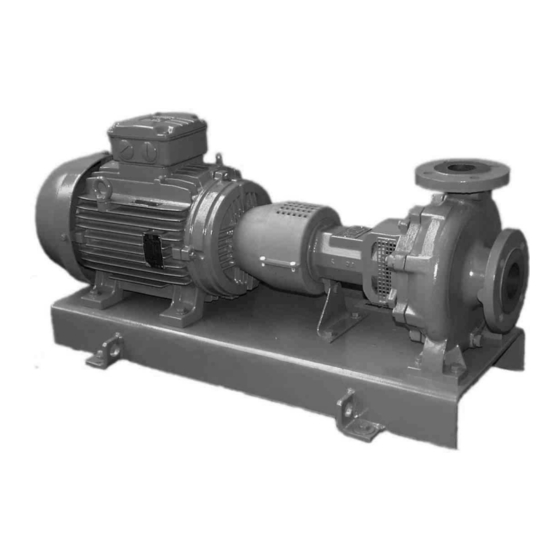
- Page 1 USER INSTRUCTIONS MHP-TN centrifugal pump Installation Operation Maintenance Single-stage, axial suction, vertical discharge type centrifugal pump PCN=71576313 – 02/07 (E) These instructions must be read prior to installing, operating, using and maintaining this equipment.
-
Page 2: Table Of Contents
CONTENTS 1 INTRODUCTION AND SAFETY ... 4 1.1 General ...4 1.2 CE marking and approvals... 4 1.3 Disclaimer... 4 1.4 Copyright... 4 1.5 Duty conditions... 4 1.6 Safety... 5 1.7 Nameplate and safety labels ... 8 1.8 Specific machine performance ... 8 1.9 Noise level... - Page 3 INDEX Additional sources (10.3) ...27 Alignment of shafting (see 4.2, 4.4 and 4.7) ATEX marking (1.6.4.2) ... 7 CE marking and approvals (1.2)... 4 Certification (9)...27 Change notes (10.2)...27 Cleaning prior to operation (5.8.1) ...21 Commissioning, start-up, operation (5)... 17 Compliance, ATEX (1.6.4.1)...
-
Page 4: Introduction And Safety
1 INTRODUCTION AND SAFETY 1.1 General These instructions must always be kept close to the product's operating location or directly with the product. Flowserve products are designed, developed and manufactured with state-of-the-art technologies in modern facilities. The unit is produced with great care and commitment to continuous quality control, utilizing sophisticated quality techniques, and safety requirements. -
Page 5: Safety
1.6 Safety 1.6.1 Summary of safety markings These User Instructions contain specific safety markings where non-observance of an instruction would cause hazards. The specific safety markings are: This symbol indicates electrical safety instructions where non-compliance will involve a high risk to personal safety or the loss of life. This symbol indicates safety instructions where non-compliance would affect personal safety and could result in loss of life. -
Page 6: Compliance, Atex (1.6.4.1)
HAZARDOUS LIQUIDS When the pump is handling hazardous liquids care must be taken to avoid exposure to the liquid by appropriate sitting of the pump, limiting personnel access and by operator training. If the liquid is flammable and/or explosive, strict safety procedures must be applied. -
Page 7: Alignment Of Shafting (See 4.2, 4.4 And 4.7) Atex Marking (1.6.4.2)
1.6.4.2 Marking An example of ATEX equipment marking is shown below. The actual classification of the pump will be engraved on the nameplate. II 2 GD c IIC 135 ºC (T4) Equipment Group I = Mining II = Non-mining Category 2 or M2 = High level protection 3 = normal level of protection Gas and/or Dust... -
Page 8: Nameplate And Safety Labels
1.6.4.5 Preventing sparks To prevent a potential hazard from mechanical contact, the coupling guard must be non-sparking. To avoid the potential hazard from random induced current generating a spark the ground contact on the baseplate must be used. Avoid electrostatic charge: do not rub non- metallic surfaces with a dry cloth, ensure cloth is damp. -
Page 9: Noise Level
3 dBA tolerance and cannot be guaranteed. Motor size 3 550 r/min and speed kW (hp) Pump only < 0.55 (< 0.75) 0.75 (1) 1.1 (1.5) 1.5 (2) -
Page 10: Transport And Storage
In areas where the staff has to intervene, remember that when the level of the sound pressure is: below 70 dBA: it is not necessary to take special precautions. above 70 dBA: people working continuously in the machine room must be supplied with protective devices against noise. -
Page 11: Storage
Motor pump unit Bareshaft pump When handling always wear gloves, safety boots and an industrial safety helmet. For masses above 25 kg (55 lb), manual handling is forbidden. 2.4 Storage Store the pump in a clean, dry location away from vibration. Leave piping connection covers in place to keep dirt and other foreign material out of pump casing. -
Page 12: Nomenclature
3.2 Nomenclature Characteristics shown on the nameplate fixed on the pump are as shown below: Each pump is supplied with the following nameplate: Speed of rotation Pump type Flow rate Head Radial/thrust bearing Year of construction + Manufacture number Each pump unit is supplied with the following nameplate: Mass of the set 3.3 Coverage charts 3.3.1 2900 min... -
Page 13: Installation
4 INSTALLATION Equipment operated in hazardous locations must comply with the relevant explosion protection regulations. See section 1.6.4, Products used in potentially explosive atmospheres. All equipment must be grounded. 4.1 Location The pump should be located to allow room for access, ventilation, maintenance and inspection with ample headroom for lifting and should be as close as practicable to the supply of liquid to be... -
Page 14: Grouting
4.3 Grouting 4.3.1 Base plate grouting a) Prepare the site for grouting. Before grouting clean the foundation surface thoroughly and provide external barriers as shown: b) Prepare grouting product (concrete, resin) in accordance with manufacturers' instructions. c) Use grouting products with anti-shrinking components. -
Page 15: Piping
It is only necessary to rectify the adjustment under base plate. If it proves to be insufficient, modify the motor and the piping. Pump and motor mounted on individual base plates: Machines are (or must be) first mounted on their own base plate in the workshop. -
Page 16: Electrical Connections
c) If high points cannot be avoided in suction line, provide them with air relief cocks. d) If a strainer is necessary, its net area should be three or four times the area of the suction pipe. e) If an inlet valve is necessary, choose a model with direct crossing. -
Page 17: Final Shaft Alignment Check
The identification nameplate should be checked to ensure the power supply is appropriate. A device to provide emergency stopping shall be fitted. Carry out the ground connections according to the current local regulations. To avoid any risk of jamming, the direction of rotation will be checked after priming of the pump (§... -
Page 18: Starting The Pump
5.3.1 Priming of a flooded pump a) As discharge valve is closed, fill the pump by opening the valve at suction. Let air escape by removing the plugs located on the pump. b) The discharge pipe is headed and there is a by-pass valve on the check valve, open slightly the discharge valve and the by-pass of the check valve. -
Page 19: Running The Pump
5.5 Running the pump 5.5.1 Venting the pump Vent the pump to enable all trapped air to escape taking due care with hot or hazardous liquids. Under normal operating conditions, after the pump has been fully primed and vented, it should be unnecessary to re-vent the pump. -
Page 20: Stopping And Shutdown
Check actual capability of the driver and control/starting system before commissioning. Maximum stop/starts Motor rating kW (hp) Up to 15 (20) Between 15 (20) and 90 (120) 90 (120) to 150 (200) -
Page 21: Pumps For Food Use Or Potable Water
Also for a given flow rate the power absorbed increases with increased viscosity, and reduces with reduced viscosity. It is important that checks are made with your nearest Flowserve office if changes in viscosity are planned. 5.7.3 Pump speed Changing pump speed effects flow, total head, power absorbed, NPSH , noise and vibration. -
Page 22: Maintenance Schedule
When air or compressed inert gas is used in the maintenance process, the operator and anyone in the vicinity must be careful and have the appropriate protection. Do not spray air or compressed inert gas on skin. Do not direct an air or gas jet towards other people. -
Page 23: Gland Packing (6.2.4)
If a check shows a bad running of the motor pump unit, the user must: Refer to the "fault finding chart" chapter 7 of this leaflet to apply the recommended solutions. b) Ensure that your equipment corresponds to the arrangements of this leaflet. c) Contact Flowserve after-sales Department if the problem persists. -
Page 24: Spare Parts
6.3 Spare parts 6.3.1 Ordering of spares Flowserve keeps records of all pumps that have been supplied. When ordering spares the following information should be quoted: 1) Pump serial number. 2) Pump size. 3) Part name 4) Part number 5) Number of parts required. The pump size and serial number are shown on the pump nameplate. -
Page 25: Faults; Causes And Remedies
7 FAULTS; CAUSES AND REMEDIES POSSIBLE CAUSES Pump or suction pipe not completely filled Air bubbles in pipes Suction level too low Wrong rotation The motor is running on 2 phases only ... -
Page 26: Parts List And Drawings
MHP-TN USER INSTRUCTIONS ENGLISH 71576313 - 02/07 8 PARTS LIST AND DRAWINGS 8.1 Sectional drawings 9331 flowserve.com Page 26 of 28... -
Page 27: Sectional Drawings Part List
8.2 Sectional drawings part list ITEM DESIGNATION 1110 Pump casing 1221 Casing cover with stuffing box 1500 Wear ring 2110 Pump shaft 2250 Radial flow impeller 2450 Shaft sleeve 2540 Thrower 2905 Plain washer 2912 Self-braked nut 3011 Radial ball bearing 3134 Support foot 3200... - Page 28 Your Flowserve factory contacts: Flowserve Pompes 13, rue Maurice Trintignant 72234 Arnage Cedex, France Telephone (24 hours): +33 2 43 40 58 47 Sales & Admin: +33 2 43 40 57 57 Repair & Service Fax: +33 2 43 40 58 17 Local Flowserve factory representatives: North America: Flowserve Pump Division...
Need help?
Do you have a question about the Centrifugal Pump MHP-TN and is the answer not in the manual?
Questions and answers