Table of Contents
Advertisement
Quick Links
Advertisement
Table of Contents

Related Manuals for Flowserve FM Centrifugal Pump PCN=71576526


Summary of Contents for Flowserve FM Centrifugal Pump PCN=71576526
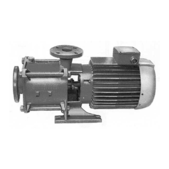
- Page 1 USER INSTRUCTIONS Installation FM centrifugal pump Operation Maintenance Multi-stage, centrifugal close-coupled pump with an axial suction and a vertical axis discharge PCN=71576526 – 03/07 (E) These instructions must be read prior to installing, operating, using and maintaining this equipment.
-
Page 2: Table Of Contents
CONTENTS 1 INTRODUCTION AND SAFETY ... 4 1.1 General ... 4 1.2 CE marking and approvals... 4 1.3 Disclaimer... 4 1.4 Copyright... 4 1.5 Duty conditions... 4 1.6 Safety... 5 1.7 Nameplate and safety labels ... 8 1.8 Specific machine performance ... 8 1.9 Noise level... - Page 3 INDEX Additional sources (10.3) ...29 ATEX marking (1.6.4.2)...7 CE marking and approvals (1.2)...4 Certification (9) ...29 Change notes (10.2) ...29 Cleaning prior to operation (5.8.1)...22 Commissioning, start-up, operation (5)... 18 Compliance, ATEX (1.6.4.1)...6 Configurations (3.1) ...11 Copyright (1.4)...4 Coverage charts (3.3) ... 13 Direction of rotation (5.1)...18 Disassembly (6.5) ...25 Discharge piping (4.3.3) ...16...
-
Page 4: Introduction And Safety
1 INTRODUCTION AND SAFETY 1.1 General These instructions must always be kept close to the product's operating location or directly with the product. Flowserve products are designed, developed and manufactured with state-of-the-art technologies in modern facilities. The unit is produced with great care and commitment to continuous quality control, utilizing sophisticated quality techniques, and safety requirements. -
Page 5: Safety
1.6 Safety 1.6.1 Summary of safety markings These User Instructions contain specific safety markings where non-observance of an instruction would cause hazards. The specific safety markings are: This symbol indicates electrical safety instructions where non-compliance will involve a high risk to personal safety or the loss of life. This symbol indicates safety instructions where non-compliance would affect personal safety and could result in loss of life. - Page 6 HAZARDOUS LIQUIDS When the pump is handling hazardous liquids care must be taken to avoid exposure to the liquid by appropriate sitting of the pump, limiting personnel access and by operator training. If the liquid is flammable and/or explosive, strict safety procedures must be applied.
-
Page 7: Fm User Instructions English 71576526
1.6.4.2 Marking An example of ATEX equipment marking is shown below. The actual classification of the pump will be engraved on the nameplate. II 2 GD c IIC 135 ºC (T4) Equipment Group I = Mining II = Non-mining Category 2 or M2 = High level protection 3 = normal level of protection Gas and/or Dust... -
Page 8: Nameplate And Safety Labels
1.6.4.5 Preventing sparks To prevent a potential hazard from mechanical contact, the coupling guard must be non-sparking. To avoid the potential hazard from random induced current generating a spark the ground contact on the baseplate must be used. Avoid electrostatic charge: do not rub non- metallic surfaces with a dry cloth, ensure cloth is damp. -
Page 9: Noise Level
3 dBA tolerance and cannot be guaranteed. Motor size 3 550 r/min and speed kW (hp) Pump only < 0.55 (< 0.75) 0.75 (1) 1.1 (1.5) 1.5 (2) -
Page 10: Transport And Storage
In areas where the staff has to intervene, remember that when the level of the sound pressure is: below 70 dBA: it is not necessary to take special precautions. above 70 dBA: people working continuously in the machine room must be supplied with protective devices against noise. -
Page 11: Lifting
All motors (for masses see the motor description plate) must be handled with a winch. For masses above 25 kg (55 lb), manual handling is forbidden. 2.3 Lifting 2.3.1 Slinging of motor pumps units Use handling means in accordance with motor pump unit mass mentioned on the CE plate. -
Page 12: Nomenclature
Maximum working pressure at discharge ...25 bar (363 psi) Maximum working pressure at suction ...16 bar (232 psi) Maximum pumped fluid temperature 105 °C (221 °F): Impeller and diffuser Cast iron or Bronze Minimum pumped fluid temperature ...-10 °C (14 °F) ... -
Page 13: Coverage Charts
FM USER INSTRUCTIONS ENGLISH 71576526 - 03/07 3.3 Coverage charts 3.3.1 2850 min (50 Hz): Operating ranges (Q, H) flowserve.com Page 13 of 32... - Page 14 FM USER INSTRUCTIONS ENGLISH 71576526 - 03/07 flowserve.com Page 14 of 32...
-
Page 15: Installation
4 INSTALLATION Equipment operated in hazardous locations must comply with the relevant explosion protection regulations. See section 1.6.4, Products used in potentially explosive atmospheres. All equipment must be grounded. 4.1 Location The pump should be located to allow room for access, ventilation, maintenance and inspection with ample headroom for lifting and should be as close as practicable to the supply of liquid to be pumped. -
Page 16: Suction Piping (4.3.2)
Vertical pipework (1"1/2) (67) perpendicular to the shaft (2") (90) Axial pipework (2") (101) parallel to the axis (2"1/2) (130) Forces and moments values are applied to the whole flanges and not flange by flange. Ensure piping and fittings are flushed before use. -
Page 17: Electrical Connections
The non-return valve will be set in the discharge pipe to protect the pump from any excessive pressure surge and from reverse rotation. If necessary, a control manometer (pressure gauge) can be connected on the piping. Control manometer Setting of the control manometer Do not tighten flanges before the final check (see §... -
Page 18: Protection Systems
Connection wiring diagram for three phase motors: Delta connection Star connection Wire up the motor terminals according to the voltage supply, in accordance with the description plate fixed on the motor and with the connection wiring diagram mentioned on the terminal box as opposite. To avoid any risk of jamming, the direction of rotation will be checked after priming of the pump (§... -
Page 19: Starting The Pump
Air escape Priming of a flooded pump 5.3.2 Priming of a sump suction pump * With foot valve: a) Fill suction pipe and casing with liquid from an independent source (pressure 1 to 2 bars or 15 to 30 psi). b) Let air escape by removing the plugs located on the piping. - Page 20 5.5.2 Pump fitted with a stuffing box If the pump has a packed gland there must be some leakage from the gland. Gland nuts should initially be finger-tight only. Leakage should take place soon after the stuffing box is pressurized. If no leakage takes place the packing will begin to overheat.
-
Page 21: Stopping And Shutdown
Check actual capability of the driver and control/starting system before commissioning. Maximum start ups per Motor rating kW (hp) Up to 15 (20) Between 15 (20) and 90 (120) 90 (120) to 150 (200) -
Page 22: Hydraulic, Mechanical And Electrical Duty
5.7 Hydraulic, mechanical and electrical duty This product has been supplied to meet the performance specifications of your purchase order, however it is understood that during the life of the product these may change. The following notes may help the user decide how to evaluate the implications of any change. -
Page 23: Maintenance Schedule
Before restarting the machine, the relevant instructions listed in section 5, Commissioning, start up, operation and shut down must be observed. Oil and grease leaks may make the ground slippery. Machine maintenance must always begin and finish by cleaning the ground and the exterior of the machine. -
Page 24: Gland Packing (6.2.5)
6.2.2 Routine inspection (daily/weekly) The following checks should be made and the appropriate action taken to remedy any deviations: a) Check the behavior of the pump while running: noise level, vibrations, bearings temperature, flow rate and pressure. b) Pump fitted with a stuffing box: leakage of 20 drops per minute. -
Page 25: Spare Parts
After setting the last packing, fix the gland on the packing and screw up the nut by hand. After this screwing phase, the shaft should turn by hand as easily as before the setting of the packing. Dimensions in Pump mm (in.) type 50 FM... - Page 26 DISCONNECT THE UNIT FROM POWER b) Close the inlet valve (if fitted) and outlet valve. c) Wait for the moment when the pump casing is cooled and at ambient temperature. DRAIN PUMP e) Dismantle inlet and outlet pipeworks as well as all pipeworks.
-
Page 27: Faults; Causes And Remedies
7 FAULTS; CAUSES AND REMEDIES POSSIBLE CAUSES Pump or suction pipe not completely filled Air bubbles in pipes Suction level too low Wrong rotation The motor is running on 2 phases only ... -
Page 28: Parts List And Drawings
FM USER INSTRUCTIONS ENGLISH 71576526 - 03/07 8 PARTS LIST AND DRAWINGS 8.1 Sectional drawing flowserve.com Page 28 of 32... -
Page 29: Sectional Drawing Parts List
8.2 Sectional drawing parts list ITEM NOMENCLATURE 1130 Suction casing 1140 Discharge casing 1150 Stage casing 1410 Diffuser 1470 Diffuser plate 2250 Radial impeller 2410 Interstage sleeve 2450 Shaft sleeve 2540 Thrower 2905 Washer 2910 Shaft nut 4120 Gland 4130 Gland packing 4132 Stuffing box bushing... - Page 30 FM USER INSTRUCTIONS ENGLISH 71576526 - 03/07 Nota: flowserve.com Page 30 of 32...
- Page 31 FM USER INSTRUCTIONS ENGLISH 71576526 - 03/07 Nota: flowserve.com Page 31 of 32...
- Page 32 Your Flowserve factory contacts: Flowserve Pompes 13, rue Maurice Trintignant 72234 Arnage Cedex, France Telephone (24 hours): +33 2 43 40 58 47 Sales & Admin: +33 2 43 40 57 57 Repair & Service Fax: +33 2 43 40 58 17 Local Flowserve factory representatives: North America: Flowserve Pump Division...
Need help?
Do you have a question about the FM Centrifugal Pump PCN=71576526 and is the answer not in the manual?
Questions and answers