Table of Contents
Advertisement
Quick Links
Advertisement
Table of Contents

Related Manuals for Flowserve HPXM


Summary of Contents for Flowserve HPXM
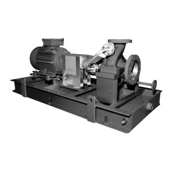
- Page 1 USER INSTRUCTIONS HPXM centrifugal pumps Installation Operation Single stage, single suction, radially split volute type Maintenance centrifugal pumps PCN=14983571 – 03/11 (E) Original instructions These instructions must be read prior to installing, operating, using and maintaining this equipment.
-
Page 2: Table Of Contents
HPXM USER INSTRUCTIONS ENGLISH 14983571 - 03/11 CONTENTS PAGE PAGE CONTENTS ............... 2 6 MAINTENANCE ............30 6.1 General ............30 1 INTRODUCTION AND SAFETY ......4 6.2 Maintenance schedule........30 1.1 General ............4 6.3 Spare parts .............32 1.2 CE marking and approvals....... 4 6.4 Recommended spares (according to API) ..32... - Page 3 HPXM USER INSTRUCTIONS ENGLISH 14983571 - 03/11 INDEX PAGE PAGE Recycling and end of product life (2.5) ....12 Additional sources of information (10.3)....46 Replacement parts (see 6.3 and 6.4).......32 Alignment of shafting (see 4.5, 4.7 and 4.3) Running the pump (see 5.6)........28 Assembly (6.9)............
-
Page 4: Introduction And Safety
HPXM USER INSTRUCTIONS ENGLISH 14983571 - 03/11 machinery and equipment and the satisfactory 1 INTRODUCTION AND SAFETY provision technical documents safety instructions. Where applicable this document 1.1 General incorporates information relevant to these Directives and Approvals. To confirm the Approvals applying... -
Page 5: Safety
HPXM USER INSTRUCTIONS ENGLISH 14983571 - 03/11 If the conditions of service on your purchase order are Always coordinate repair activity with operations and going to be changed (for example liquid pumped, health and safety personnel, and follow all plant... - Page 6 HPXM USER INSTRUCTIONS ENGLISH 14983571 - 03/11 immediate area. Note: bearing housings must not be insulated and drive motors and bearings may be hot. HAZARDOUS LIQUIDS If the temperature is greater than 80 °C (175 °F) or When the pump is handling hazardous liquids care below -5 °C (20 °F) in a restricted zone, or...
- Page 7 HPXM USER INSTRUCTIONS ENGLISH 14983571 - 03/11 1.6.4.2 Marking responsibility compliance with An example of ATEX equipment marking is shown specified maximum liquid temperature is with the below. The actual classification of the pump will be plant operator. engraved on the nameplate.
-
Page 8: Nameplate And Warning Labels
HPXM USER INSTRUCTIONS ENGLISH 14983571 - 03/11 is a risk from such tools or materials, maintenance 1.6.4.5 Preventing sparks must be conducted in a safe area. To prevent a potential hazard from mechanical contact, the coupling guard must be non-sparking It is recommended that a maintenance plan and and anti-static for Category 2. -
Page 9: Noise Level
HPXM USER INSTRUCTIONS ENGLISH 14983571 - 03/11 The dBA values are based on the noisiest ungeared 1.9 Noise level electric motors that are likely to be encountered. When pump noise level exceeds 85 dBA attention They are Sound Pressure levels at 1 m (3.3 ft) from must be given to prevailing Health and Safety the directly driven pump, for "free field over a... -
Page 10: Transport And Storage
HPXM USER INSTRUCTIONS ENGLISH 14983571 - 03/11 2 TRANSPORT AND STORAGE 2.1 Consignment receipt and unpacking Immediately after receipt of the equipment it must be checked against the delivery and shipping documents for its completeness and that there has been no damage in transportation. - Page 11 HPXM USER INSTRUCTIONS ENGLISH 14983571 - 03/11 2.4.1 Long term storage The pump shaft should be rotated, in the direction of During extended periods storage prior rotation, at least 1 and 1/4 turns each week during installation, precautions must be taken to protect the the storage period and any other periods of stand by.
-
Page 12: Recycling And End Of Product Life
Manager of Customer Service, stating in 3.1 Configurations detail the results of the inspection. The type HPXM pump is a single stage, horizontal, One month prior to installation of the equipment, a end suction process pump with overhung impeller... - Page 13 HPXM USER INSTRUCTIONS ENGLISH 14983571 - 03/11 and then through the volute to the discharge nozzle. by a shaft mounted metal slinger that transfers oil to The casing has mounting feet integrally cast on the bearing feed galleries within the housing wall.
-
Page 14: Performance And Operating Limits
HPXM USER INSTRUCTIONS ENGLISH 14983571 - 03/11 3.3.13 Accessories ensure the maximum pump working pressure is not Accessories may be fitted when specified by the exceeded, driver overloaded, customer. NPSH >NPSH , and that noise and vibration are Baseplates are fabricated and machined so to within local requirements and regulations. -
Page 15: Installation
HPXM USER INSTRUCTIONS ENGLISH 14983571 - 03/11 additional flow paths until the given unit re- 4.3 Foundation establishes the acceptable temperature rise, and sets off alarms if not achieved within reasonable/normal There are many methods of installing time periods. (High limit could actually shut down pump units to their foundations. - Page 16 HPXM USER INSTRUCTIONS ENGLISH 14983571 - 03/11 Prepare sufficient steel plates to be placed below each baseplate jacking screw furnished with the baseplate. The purpose of the plate is to spread the load of the screw without crushing the concrete below.
-
Page 17: Grouting
HPXM USER INSTRUCTIONS ENGLISH 14983571 - 03/11 structure. This may have disturbed the baseplate, Pour grout until level reaches top of dam. so re-check the levels. Allow to dry sufficiently to prevent grout from Ensure that shaft alignment per Section 4.5 can overflowing while completing the remaining grouting. -
Page 18: Initial Alignment
HPXM USER INSTRUCTIONS ENGLISH 14983571 - 03/11 4.5 Initial alignment 4.5.1 Thermal expansion The pump and motor will normally have to be aligned at ambient temperature and should be corrected to allow for thermal expansion at operating temperature. Figure 4.7 4.5.2 Alignment methods... - Page 19 HPXM USER INSTRUCTIONS ENGLISH 14983571 - 03/11 and loosen off the holding down bolt while noting any Angular 0.025 mm (0.001 in.) TIR deflection reading on the Dial Test Indicator - a maximum of 0.05 mm (0.002 in.) is considered...
-
Page 20: Piping
HPXM USER INSTRUCTIONS ENGLISH 14983571 - 03/11 g) Coupling guard correctly installed? 4.6 Piping Never use the pump as a support for piping 4.6.1 General These units are furnished for a particular service condition. Changes in the hydraulic system may affect performance adversely. - Page 21 HPXM USER INSTRUCTIONS ENGLISH 14983571 - 03/11 a) The inlet pipe should be one or two sizes larger Pressure gauges should be installed on both sides of than the pump inlet bore and pipe bends should the screen so that the pressure drop across the be as large radius as possible.
-
Page 22: Final Shaft Alignment Check
A device to provide emergency stopping must order requirements. be fitted. The "HPXM" pump can be arranged with either a single, dual mechanical pump seal. Refer to the If not supplied pre-wired to the pump unit, the General Arrangement for piping connections to be controller/starter electrical details will also be supplied used with your pump. - Page 23 HPXM USER INSTRUCTIONS ENGLISH 14983571 - 03/11 b) Ensure the pump and piping is clean. Before putting the pump into operation, the piping should be thoroughly back flushed to remove any foreign matter which may have accumulated during installation. Take all possible care not to contaminate your system.
- Page 24 HPXM USER INSTRUCTIONS ENGLISH 14983571 - 03/11 • (3)-(4) the oil is collected by the oil collector and reaches the thrust bearing through the hole “F” • (6) the oil is collected behind the thrust bearings and returns into the oil sump once it flows into the thrust bearings •...
- Page 25 HPXM USER INSTRUCTIONS ENGLISH 14983571 - 03/11 recovery trap to bottom opening or leave it open to For oil lubricated pumps, fill the act as a relief. Refer to Figure 5.5 for details. bearing housing with correct grade of oil to the correct level, i.e.
-
Page 26: Pump Lubricants
HPXM USER INSTRUCTIONS ENGLISH 14983571 - 03/11 5.2 Pump lubricants 5.2.1 Recommended oil lubricants Oil Ring or Slinger Lubrication Pure Oil Mist Lubrication Lubrication service Ball Bearing Type Mineral Oil Mineral Oil (Petroleum Based) (Petroleum Based) Viscosity mm ²/s 40 ºC [cSt]... -
Page 27: Direction Of Rotation
HPXM USER INSTRUCTIONS ENGLISH 14983571 - 03/11 If a synthetic lubricant (fire resistant fluid) is to be checked against the order. There may be used instead of the normal type oil for the lubrication requirements for an external clean supply, particular of bearings, gears etc., the material of all gaskets and... -
Page 28: Starting The Pump
HPXM USER INSTRUCTIONS ENGLISH 14983571 - 03/11 h) Turn on cooling liquid and assure correct flow Ensure the inlet pipe and pump casing exists (to cooler, insert gland etc.) as specified. are completely full of liquid before starting continuous Double check pump rotation by starting unit duty operation. -
Page 29: Normal Start Up
HPXM USER INSTRUCTIONS ENGLISH 14983571 - 03/11 Check for vibrations. should then remain constant or marginally reduce g) Check for adequate flow of cooling liquids. with time. h) Check for hot alignment: for services 55 °C (100 5.7.4 Normal vibration levels, alarm and trip °F) and more above ambient, after unit has been... -
Page 30: Hydraulic, Mechanical And Electrical Duty
HPXM USER INSTRUCTIONS ENGLISH 14983571 - 03/11 areas where maintenance and inspection are to be If pump stops abruptly when driver is carried out. The positioning of these accessories shut down, investigate for pump binding. Take must not limit access or hinder the lifting of the part to necessary remedial action before restarting be serviced. - Page 31 HPXM USER INSTRUCTIONS ENGLISH 14983571 - 03/11 d) Check that the duty condition is in the safe 6.2.2 Periodic inspection (monthly) operating range for the pump. a) Check lubricant contamination whether e) Check vibration, noise level surface bearing oil, or seal oil (if applicable) by sample...
-
Page 32: Spare Parts
2” (M 50) screws/nuts • Socket spanners (wrenches), up to 2” (M 50) 6.3.1 Ordering of spares screws Flowserve keep records of all pumps that have been • Allen keys, up to 10 mm (A/F) supplied. When ordering spares the following •... -
Page 33: Disassembly
HPXM USER INSTRUCTIONS ENGLISH 14983571 - 03/11 Inboard/Outboard Flingers & Oil Thrower When pump is handling "hot" liquid extreme Torque Value Socket Head care must be taken to ensure safety of personnel (lb ft) Capscrew Size when attempting to drain pump. Hot pumps must ¼... - Page 34 HPXM USER INSTRUCTIONS ENGLISH 14983571 - 03/11 h) Correctly support pumping element in horizontal e) Place the bearing housing in a vertical position, position. For non-inducer machines release (coupling end up) on blocking. Blocking must be impeller locking screws and locknut on impeller.
-
Page 35: Examination Of Parts
HPXM USER INSTRUCTIONS ENGLISH 14983571 - 03/11 6.8 Examination of parts Do not spin dirty bearings. Rotate them slowly while washing. Used parts must be inspected before assembly to ensure the pump will subsequently run d) Dry thoroughly cleaned bearings. If an air hose is properly. - Page 36 HPXM USER INSTRUCTIONS ENGLISH 14983571 - 03/11 6.9.2 Bearings Housing sufficiently so that it will not move from position. The ball bearings require correct handling and Cover bearings to protect them from dirt. installation to ensure optimum performance. The following information is intended as a minimum to...
- Page 37 HPXM USER INSTRUCTIONS ENGLISH 14983571 - 03/11 6.9.4 Casing assembly a) For non-inducer machines install impeller. Install locking nut - noting left hand thread form. Torque nut to correct tightness. Fit and tighten lockscrew on end of locknut throat bush (if fitted).
-
Page 38: Faults; Causes And Remedies
HPXM USER INSTRUCTIONS ENGLISH 14983571 - 03/11 7 FAULTS; CAUSES AND REMEDIES FAULT SYMPTOM P u m p o v e r h e a ts a n d s e i z e s ⇓ ⇓ B e a r i n g s h a v e s h o r t l i f e ⇓... - Page 39 HPXM USER INSTRUCTIONS ENGLISH 14983571 - 03/11 FAULT SYMPTOM P u m p o v e r h e a ts a n d s e i z e s ⇓ B e a r i n g s h a v e s h o r t l i f e ⇓...
-
Page 40: Parts List And Drawings
HPXM USER INSTRUCTIONS ENGLISH 14983571 - 03/11 8 PARTS LIST AND DRAWINGS 8.1 Slinger Lubrication 8.1.1 Parts list Ref no Description 1221 Casing Cover 4132 Stuffing Box Bushing 1100 Casing 3862 Lubricating Disk Thrower 6811 Cylindrical Pin 3855 Constant Level Oiler 6700.2... - Page 41 HPXM USER INSTRUCTIONS ENGLISH 14983571 - 03/11 8.2 Slinger Lubrication, Improseal 8.2.1 Parts list Ref no Description 2100 Shaft 4300.1 Bearing Isolator 1410 Diffuser 4200 Mechanical Seal 1221 Casing Cover 4132 Stuffing Box Bushing 1100 Casing 3862 Lubricating Disk Thrower...
- Page 42 HPXM USER INSTRUCTIONS ENGLISH 14983571 - 03/11 8.3 Slinger Lubrication, Water Cooling 8.3.1 Parts list Ref no Description 6811 Cylindrical Pin 4132 Stuffing Box Bushing 6700.2 3862 Lubricating Disk Thrower 6700.1 3855 Constant Level Oiler 6581.2 Hexagon Nut 3854 Oil Filter Plug 6581.1...
- Page 43 HPXM USER INSTRUCTIONS ENGLISH 14983571 - 03/11 8.4 Slinger Lubrication, Fan Cooling 8.4.1 Parts list Ref no Description 8161 4132 Stuffing Box Bushing 6811 Cylindrical Pin 3862 Lubricating Disk Thrower 6700.2 3855 Constant Level Oiler 6700.1 3854 Oil Filter Plug 6581.2...
- Page 44 HPXM USER INSTRUCTIONS ENGLISH 14983571 - 03/11 8.5 Pure Oil Mist Lubrication 8.5.1 Parts list Ref no Description 1410 Diffuser 4330.2 Labyrinth Ring 1221 Casing Cover 4330.1 Labyrinth Ring 1100 Casing 4200 Mechanical Seal 6811 Cylindrical Pin 4132 Stuffing Box Bushing 6700.2...
- Page 45 HPXM USER INSTRUCTIONS ENGLISH 14983571 - 03/11 8.6 Slinger Lubrication, Inducer 8.6.1 Parts list Ref no Description 1100 Casing 4132 Stuffing Box Bushing 6811 Cylindrical Pin 3862 Lubricating Disk Thrower 6700.2 3855 Constant Level Oiler 6700.1 3854 Oil Filter Plug 6581.2...
-
Page 46: Certification
HPXM USER INSTRUCTIONS ENGLISH 14983571 - 03/11 8.7 General arrangement drawing 10.3 Additional sources of information The typical general arrangement drawing and any specific drawings required by the contract will be Reference 1: sent to the Purchaser separately unless the... - Page 47 HPXM USER INSTRUCTIONS ENGLISH 14983571 - 03/11 NOTES: Page 47 of 48...
- Page 48 HPXM USER INSTRUCTIONS ENGLISH 14983571 - 03/11 FLOWSERVE REGIONAL Your Flowserve factory contacts: SALES OFFICES: Service & Warranty: USA and Canada Flowserve Flow Solutions Group - Italy Flowserve Corporation Worthington S.r.l. 5215 North O’Connor Blvd., Via Rossini, 90/92 Suite 2300...
Need help?
Do you have a question about the HPXM and is the answer not in the manual?
Questions and answers