Table of Contents
Advertisement
Quick Links
Instruction Manual
GK-405
Vibrating Wire Readout
No part of this instruction manual may be reproduced, by any means, without the written consent of Geokon, Inc.
The information contained herein is believed to be accurate and reliable. However, Geokon, Inc. assumes no responsibility for
errors, omissions, or misinterpretation. The information herein is subject to change without notification.
Copyright © 2013-2018 by Geokon, Inc.
(Doc Rev I, 05/03/2018)
Advertisement
Table of Contents
Troubleshooting

Subscribe to Our Youtube Channel
Related Manuals for Geokon GK-405


Summary of Contents for Geokon GK-405
- Page 1 Vibrating Wire Readout No part of this instruction manual may be reproduced, by any means, without the written consent of Geokon, Inc. The information contained herein is believed to be accurate and reliable. However, Geokon, Inc. assumes no responsibility for errors, omissions, or misinterpretation.
- Page 3 Upon examination by Geokon, if the unit is found to be defective, it will be repaired or replaced at no charge. However, the WARRANTY is VOID if the unit shows evidence of having been tampered with...
-
Page 5: Table Of Contents
..................6 STABLISHING ONTACT WITH THE EMOTE ODULE 2.4 I GK-405 VWRA ........................11 NSTALLING THE 2.4.1 Launching the GK-405 Installer ....................... 13 2.5 S ................16 TARTING THE IBRATING EADOUT THE IRST 3. USER INTERFACE .............................. 19 3.1 O ................................. - Page 6 APPENDIX A. GK-405 CONNECTIONS .......................58 A.1 S ...........................58 INGLE ENSOR ONNECTION A.2 L ..........................59 ONNECTION A.2.1 Connecting to a Load Cell with 10-pin attached ..................60 A.2.2 Connecting to a Load Cell with Flying Leads ..................60 A.3 C ..........................61 HARGER ONNECTIONS APPENDIX B.
- Page 7 21 - GK-405 I HDD ..................... 14 IGURE NSTALLER AT ROOT OF 22 - GK-405 I ......................... 15 IGURE NSTALL CREEN 23 - GK-405 VWRA I ->P ..................15 IGURE CON IN TART ROGRAMS 24 - S ........................16 IGURE...
- Page 8 55 - S ..............33 IGURE ENSOR ELECTION CREEN EMOTE ODULE ONNECTED 56 - T ..........................34 IGURE ERMINAL INDOW 57 - F ..........................35 IGURE PTIONS 58 - D ........................35 IGURE ELETE ILES INDOW 59 - E ............................36 IGURE XPORT 60 - E ...........................36 IGURE XPORT...
-
Page 9: Introduction
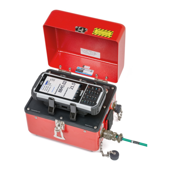
• The Readout Unit, consisting of a Windows Mobile handheld PC running the GK-405 Vibrating Wire Readout Application • The GK-405 Remote Module is housed in a weatherproof enclosure and connects to the vibrating wire gage to be measured. Figure 1 - GK-405 with Handheld PC in Cradle (Shown with the FPC-2) The two components communicate wirelessly using Bluetooth®, a reliable digital... -
Page 10: Features
1.1 Features Rugged, general purpose, reliable readout based on a Windows Mobile handheld PC: • All the benefits of a Windows compatible device (Windows file system, RS-232, USB and wireless connectivity) • Long battery life • Ease of use Lightweight and simple Remote Module: •... -
Page 11: Gk-405 Accessories
• Three replacement fuses 1.3 GK-405 Vibrating Wire Readout Application The GK-405 Vibrating Wire Readout Application (GK-405 VWRA) installs and runs on a ruggedized handheld PC (see Figure 3) and is designed to communicate via Bluetooth with Remote Modules connected to vibrating wire gages. -
Page 12: Installation And Operation
The steps described in Sections 2.1 and 2.2 are an attempt to guide the user through the process of launching the GK-405 VWRA, connecting to the sensor, and taking a reading. If all parts of the GK-405 are purchased as a system, Geokon makes every effort to ensure that the system is completely set up and working before it leaves the factory. -
Page 13: Figure 4 - Live Readings - Raw
Selection Screen” to select a predefined sensor or to create a new sensor configuration. Please refer to Section 3.3, “Sensor Selection Screen” as well as, Section 4.2, “Sensor Configuration”. 5) To close the GK-405 VWRA from the Live Readings Screen, tap “Menu” then “Close GK- 405”. -
Page 14: Establishing Contact With The Remote Module
2.3 Establishing Contact with the Remote Module In general, this should only need to be done once and is typically done before it leaves the factory. Follow the steps below to ensure the ‘partnership’ with the remote is established before using the readout software: 1) Use the Bluetooth Settings Manager on the handheld PC to set up the link to the remote. -
Page 15: Figure 8 - Add New Device
3) Click on the “Devices” tab, if it shows a “Geokon” device (name will start with “GK405” and contain the remote’s serial number), go to step six. Otherwise, turn on the remote module (should see a flashing blue indicator on the remote) and select “Add new device…”. -
Page 16: Figure 10 - Enter Passcode
Figure 10 - Enter Passcode 6) Click on the COM Ports tab, if the “Geokon” device is already assigned to a COM Port skip to step nine. If no COM Port is assigned, tap on “New Outgoing Port”. In the example shown in Figure 11, there is no COM Port assigned to a “GK405”... -
Page 17: Figure 12 - Add A Device
7) The screen shown in Figure 12 will be displayed. Select the appropriate device from the list and tap “Next”. Figure 12 - Add a Device 8) From the “Port:” dropdown list, select a COM port (COM5 is the default). Be sure to remember the number of the COM port as you may have to select it later in the readout software (see Section 3.5.3). -
Page 18: Figure 14 - Serial Port Check
“Connect” button available at the bottom of the screen. See Figure 15 below. DO NOT USE THE “CONNECT” BUTTON TO TEST THE CONNECTION! It will always fail after the pairing has been made successfully. Test the pairing by entering the GK-405 VWRA application. Figure 15 - Connect Button... -
Page 19: Installing The Gk-405 Vwra
• Windows .NET 3.5 Compact Framework (CF) and .NET framework English Language Messages Package installed on HHD. • Both “CAB” file installers are included in the GK-405 VWRA installer “Zip” file, available on Geokon’s website (http://www.geokon.com/GK-405). • Microsoft ActiveSync version 4.5.0 or higher installed on the host PC if host PC operating on Windows XP (see Figure 16). -
Page 20: Figure 17 - Windows Mobile
Figure 17 - Windows Mobile Device Center... -
Page 21: Launching The Gk-405 Installer
2.4.1 Launching the GK-405 Installer 1) From the Windows Mobile Device Center window on the PC (see Figure 17 above) click on the folder icon labeled “Browse the contents of your device” to call up an Explorer Window for the HHD (see Figure 18). The procedure for ActiveSync is very similar. -
Page 22: Figure 20 - Installation Folder
3) Unzip the installer (downloaded from Geokon’s website), open a new Windows Explorer window, and then navigate to the root folder of the installation folder (Figure 20). Figure 20 - Installation Folder Contents 4) Copy the file, “GK405_Installer.CAB” from the installer folder to the HHD system root folder. - Page 23 Figure 22 - GK-405 Install Screen 6) The file, GK405_Installer.CAB can be now deleted from the system root folder to free up memory. The GK-405 VW Readout application is now installed and its icon should appear in “Start->Programs” (Figure 23).
-
Page 24: Starting The Vibrating Wire Readout The First Time
\Application Data\Geokon\GK-405\Workspaces. GK-405 VWRA appends the name of the new workspace to this shared folder (see Section 5) and uses it as the default location for the new workspace. The user is free to select their own location, either by entering it directly, or the Browse button ( ) may be used to navigate to a different folder location or to create a new folder (see below). -
Page 25: Figure 25 - Workspace Folder
(Figure 26). Figure 26 - Workspace Exists After the initial workspace is created, the GK-405 VWRA will attempt to connect to a remote module. If no remote module can be found then the error message shown in Figure 27 will be displayed. -
Page 26: Figure 27 - Remote Module Not Found
Figure 27 - Remote Module Not Found Note: With all subsequent attempts to connect to the Remote Module, please ensure that the “Power On” button on the Remote Module has been pressed (blue light will be blinking) before launching the GK-405 VWRA. -
Page 27: User Interface
3. USER INTERFACE 3.1 Overview Following a successful Bluetooth connection, the GK-405 VWRA will boot up displaying the screen shown in Figure 29. This is the Live Readings screen and it is shown in “Raw Readings” mode, meaning that output will be displayed in “raw” form (usually digits) since no sensor has been selected to supply parameters for engineering unit display. -
Page 28: Display Mode
Display Mode dropdown menu. See Table 1 to determine the best choice for the sensor to be measured. Figure 30 - Display Mode Dropdown Menu Display Mode Geokon Model # Calculation Units Sweep Freq.(hz) Period, T... -
Page 29: Sensor Index
View Options (Figure 33) allow functionality such as storing, saving and viewing data. In “Raw Readings” mode, the only Menu Option enabled is “Close GK-405” while valid View Option choices are “Sensor Selection Screen” (described further in Section 3.3) and “Landscape Mode”. -
Page 30: Sensor Selection Screen
These navigation controls present an organizational view of the active workspace, inform the user about the state of the application, and provide the user with tools to configure and control Geokon devices. Figure 34 - Sensor Selection Screen... -
Page 31: Project Explorer
These views reflect the hierarchical relationship between these elements. The highest element in the workspace hierarchy tree is a project. Projects allow a GK-405 VWRA user to group sensors into organizational units based on the user's preference. A project can reflect a specific site where sensors have been installed such as a construction project. -
Page 32: Figure 36 - Context Menu
Figure 38 - List of Workspace Names Figure 37 - Workspace Selection Window Alternatively, a new name can be entered in the workspace name selection box. If the GK-405 VWRA recognizes the name as a workspace it has opened before, it will reopen the existing workspace. -
Page 33: Figure 39 - Workspace Folder
If the workspace name is new to the GK-405 VWRA then a workspace folder selection window is displayed (Figure 39). Select the appropriate folder (or use the default) and a new workspace is created with the name entered above. Figure 39 - Workspace Folder Selection 3.4.1.2 Add Project... -
Page 34: Application Menu
Figure 40 - Sort Elements Sub-Items 3.5 Application Menu The GK-405 VWRA Application Menu provides access to the high-level application functionality. It is located in the lower, right corner of the main window frame (Figure 41). The “Edit Settings” menu item can also be accessed via the context menu. -
Page 35: Live Readings- With Selected Sensor
A successful connection is indicated by the icon to the right of the “Geokon” label as well as, a status of “Connected” at the bottom of the main screen. Both of the connection indicators are shown inside red ovals in Figure 42 (see Section 2.3 and 3.5.3 for information regarding connecting to the remote module). -
Page 36: Figure 44 - Live Readingss
Tapping this menu item will cause the Live Readings screen to be displayed with its parameters initialized for the specific sensor selected (Figure 44). Please refer to Appendix A for information regarding sensor connections. Figure 44 - Live Readings Screen (Sensor Selected) Much like in “Live Readings –... -
Page 37: Figure 45 - Menu Options
3.5.1.1 Menu Options The Menu options may be opened by clicking on “Menu” in the lower, left corner of the screen (Figure 45). The available Menu options are outlined below. Figure 45 - Menu Options Clear Data: Allows clearing of all readings stored (in the current session) for the selected sensor. -
Page 38: Figure 47 - Storage Configuration
“Create New File” and is not shown. Figure 47 - Storage Configuration Dialog Close GK-405: Shuts down the application and breaks the connection to the Remote Module. The user will be given the opportunity to save any stored data (from the current... -
Page 39: Figure 48 - View Options
3.5.1.2 View Options The View options may be opened by clicking on “View” in the lower, right corner of the screen (Figure 48). The available View options are outlined below. Figure 48 - View Options All Reads for this Sensor: This feature displays a window showing all stored reads for the selected sensor in the current session (Figure 49). -
Page 40: Edit Settings
Sensor Selection Screen: This option returns operation to the “Sensor Selection Screen” where other sensors may be selected, edited, or created. See Section 3.3 for more information. Landscape Mode: This “View” option and its converse, “Portrait Mode”, allow the orientation of the screen to be changed. Figure 50 shows the “Live Readings – With Selected Sensor”... -
Page 41: Figure 53 - Remote Connect With
1) Make sure the remote is turned on (blue light blinking). 2) Select the “Application” menu option “Remote Connect with” (Figure 53) and pick the COM port previously established in Section 2.3 (Figure 54). Figure 54 - Select COM Port Figure 53 - Remote Connect With... -
Page 42: Terminal Window
Typing a command in the “Command:” text box, followed by a keyboard “Enter” will cause the Remote Module to execute the command one time only. 3.5.5 About GK-405 VWRA Select this option to show the details of the GK-405 VWRA operating system. -
Page 43: File Menu
“Select All Files” checkbox to select all files. Tapping on “Select” will cause the GK-405 VWRA to prompt the user to confirm that they really want to delete the selected files. Tap on “Yes” to finish the deletion. -
Page 44: Export Menu
3.6.2 Export Menu The Export menu is used to export sensor data and project element settings to a folder of the user’s choosing (Figure 59). Figure 59 - Export Menu 3.6.2.1 Export Data The Export Data Menu Option allows exporting of data from the current sensor, selected via the Project Explorer. -
Page 45: Figure 61 - Save File Window
Once all the desired files are selected, tap “Export” to display the “Save File” window (Figure 61) where a new name and folder may be specified for each file. If more than one file was selected then a checkbox is displayed allowing the same folder to be used for each file, if desired. -
Page 46: Figure 63 - Select Sensor ( S ) To
(the default selection) (before conversion by the gage factor) of the sensor. Some Geokon sensors may contain up to six individual vibrating wire gages, therefore checking “Include Raw Readings” will add seven additional columns (six cells plus the average) to the export data. -
Page 47: Figure 64 - Select Exportf
After selecting the appropriate sensors for export, tap on “Next” to display a dialog allowing an export folder to be selected, as well as other export “mode” parameters (Figure 64). Figure 64 - Select Export Folder and Mode The mode parameters allow export “All Files” or only the “Newest File” for each sensor. Additionally, all eligible files can be combined into one export file if desired. -
Page 48: Import Menu
Figure 65 - Export Path Selection Window If no project is selected in the Project Explorer, an error message will be displayed (Figure 66). Figure 66 - No Project Selected Error 3.6.3 Import Menu The Import Menu is used to import Project Explorer element settings that were previously exported using the Export Menu functions (see Section 3.6.2.2 above). -
Page 49: View Data
Figure 67 - Select Project Export File If a project with the same name already exists in the current workspace, an error message will be displayed and the project import will be cancelled. 3.6.4 View Data When the View Data Menu is clicked and a sensor has been previously selected, the “Select File to View:”... -
Page 50: Close Gk-405
Figure 69 - Sensor Reads Window 3.6.5 Close GK-405 Tapping on this menu item will cause the program to cease execution. This behavior is... -
Page 51: Configuring Project Explorer Elements
Figure 70 - Project Settings Project ID: Read-only value, generated when the project was created. Used internally by the GK-405 VWRA. Project Name: Use the onscreen keyboard to enter a unique and descriptive name for the project. Description: Using the onscreen keyboard, enter a brief description pertaining to the project. -
Page 52: Sensor Configuration
4.2 Sensor Configuration The Sensor settings window (Figure 71) manages sensor configuration options through several different screens. The user can easily navigate between screens by tapping on the left and right arrows near the bottom of the screen ( 4.2.1 Sensor Settings Page One, General Sensor Information A detailed explanation of the parameters for the General Sensor Information window appears below. -
Page 53: Sensor Settings Page Two, Conversion Method And Coefficients
Sensor Model: The sensor model is selected from the list of supported sensor models, i.e., “45xx”. When the selected sensor model is “49xx” another parameter is displayed to allow the number of sensors per gage can be entered (see Figure 72 below). This parameter is used to detect missing gages in a multi-gage load cell. -
Page 54: Figure 74 - Linear Coefficients
4.2.2.1 Linear Conversion Method Selecting this radio button will cause the GK-405 VWRA to apply a linear conversion factor to convert subsequent readings from Digits to Engineering Units. This also enables the Linear Coefficients parameters (Figure 74). A detailed description of each of the available parameters appears below. -
Page 55: Sensor Settings Page Three, Units Conversion
4.2.2.2 Polynomial Conversion Method Selecting this radio button will cause the GK-405 VWRA to apply polynomial conversion factors to convert subsequent readings from Digits to Engineering Units This also enables the Polynomial Coefficients parameters (Figure 75). A detailed description of each of the available parameters appears below. -
Page 56: Figure 76 - Units Conversion
Conversion Factor: This parameter is dependent on Measurement, Input units and Output units selections above. This value is calculated by the GK-405 VWRA and is not editable. The Gage factor (see above) is multiplied by this factor before converting sensor reads to engineering units. -
Page 57: Sensor Settings Page Four, Temperature Settings
4.2.4 Sensor Settings Page Four, Temperature Settings The fourth page of the Sensor Setting window (Figure 77) contains parameters that allow a temperature correction factor to be applied to collected data. A detailed description of all the parameters on this page appears below: Figure 77 - Temperature Settings (Nautiz X8 Shown) 4.2.4.1 Temperature Correction Feature: (Note: Temperature Correction feature does not apply to all sensors and will be disabled... -
Page 58: Figure 78 - Nonstandardt
Thermistor Type: Allows selection of the Thermistor type. Valid selections are “Standard”, “High-Temp 8.2K”, “High-Temp 10K” or “Other”. The first three are Geokon thermistor offerings based on the type of sensor purchased. Selecting the “Other” choice causes four more text boxes to be displayed (Figure 78) where up to four thermistor coefficients may be entered if a nonstandard thermistor is used. -
Page 59: Files, Folders And Transferring Data
<PROJECT ID> can be found in each Project’s settings. 5.1 File Transfer In general, the only files generated by the GK-405 IRA that will have to be transferred are the sensor data files, although periodically archiving others on a “master” PC is recommended. -
Page 60: Backing Up Configurations
5.2 Backing up configurations To guard against accidental data loss and as a matter of good computer technique, critical data and configuration files should be periodically backed up. Entire projects can be backed up using the Project Export function from the File menu. After exporting, the resulting “.lvpe”... -
Page 61: Troubleshooting
6. TROUBLESHOOTING 6.1 Bluetooth Setup and Connection The following sections show common error messaging that may be displayed when setting up and trying to connect to the Remote Module via Bluetooth. Also included are potential solutions to the errors shown. 6.1.1 “Cannot Connect…the passcode is incorrect”... -
Page 62: Figure 80 - Bluetooth Device
Figure 80 - Bluetooth Device Context Menu This connection method will never be successful and should not be used to test the pairing. To test the pairing, use the GK-405 VWRA as outlined in Section 3.5.3. -
Page 63: Connection Problem" Error
If the error shown in Figure 81 occurs, first verify which COM port is being used by the GK-405 by checking in the COM Port section of the Windows Bluetooth settings (see Figure 82 on the following page). Select that COM Port from the GK-405 application’s COM sub-menu of the “Remote Connect with…”... -
Page 64: Figure 82 - Bluetooth Settings
Figure 82 - Bluetooth Settings Window, COM Ports Tab Figure 83 - Remote Connect With... -
Page 65: Common Troubleshooting Solutions
Check for a “background” error message. An error message may exist behind the main window that requires user input. Tap The GK-405 appears to be “hung” or “frozen” and will not respond to any key. on the “Windows” logo ( ) and then “Task Manager”... -
Page 66: Appendix A. Gk-405 Connections
APPENDIX A. GK-405 CONNECTIONS A.1 Single Sensor Connection Figure 84 shows a close-up view of the 10-pin bulkhead “Sensor” connector. Table 4 lists the pinout for this connector. Figure 84 - Single Sensor Connector 10-pin Bulkhead Alligator Clip Boot Color... -
Page 67: Load Cell Connection
A.2 Load Cell Connection Figure 85 shows a close-up view of the 10-pin Bulkhead “Load Cell” connector. Table 5 lists the pinout for this connector. Figure 85 - Load Cell Connector 10-pin Bulkhead Signal Description (PT06F-12-10P) Vibrating Wire Gage 1 + Vibrating Wire Gage 2 + Vibrating Wire Gage 3 + Vibrating Wire Gage 4 +... -
Page 68: Connecting To A Load Cell With 10-Pin Attached
Next, connect the flying leads of the GK-405 to the leads of the load cell. The individual leads will be identified as shown in the wiring diagram in Table 6. Each sensor is read in turn by clipping either the red or black clip to the lead marked “common”... -
Page 69: Charger Connections
A.3 Charger Connections To charge the remote module, plug the CHG-04 into the charger port shown in Figure 86. The CHG-04 has an LED indicator, which indicates red when the unit is charging and green when it is fully charged. Figure 86 - Charger Connection... -
Page 70: Appendix B. Changing A Fuse
APPENDIX B. CHANGING A FUSE 1) Remove the eight Philips head screws that hold the faceplate of the remote module in place. 2) Remove the faceplate by gently pulling on the readout unit cradle (Figure 87). Figure 87 - Removing the Face Plate... -
Page 71: Figure 88 - Fuse Location
3) Turn the faceplate over and locate the fuses on the circuit board (Figure 88). Figure 88 - Fuse Location 4) Remove the defective fuse and replace. 5) Make sure the rubber gasket beneath the faceplate is in place and flat against the internal flange. -
Page 72: Appendix C. Remote Module Command Structure
APPENDIX C. REMOTE MODULE COMMAND STRUCTURE COMMAND FUNCTION SYNTAX RETURN VALUE READ FIRMWARE VER#.# VERSION ####### 0000000 0000000 REQUEST 6 READS 0000000 0000000 0000000 V6(A – SET GAGES SPECTRUM %%%%%% TAKE BATTERY <sp><sp>+#.# READING TAKE +5V READING <sp><sp>+#.# SENSOR TEMPERATURE (+/-)##.#### (°C) Table 7 - Remote Module Command Format... - Page 73 Example 3: SET GAGES SPECTRUM: Set the operating “pluck” spectrum to the “B” range (1400 – 3500 Hz) for each gage: Command: V6B<CR> Response: BBBBBB Example 4: TAKE BATTERY READING: Display the current voltage level of the lithium battery: Command: V7<CR>...
-
Page 74: Appendix D. Data File Formats
APPENDIX D. DATA FILE FORMATS D.1 Raw Data Text Report When exporting, “raw” text data is the default for the Extended Format options of the “Export Data Menu” (see Section 3.6.2.1). 2013,140,10,28,28,.83,21.8,9196.9,0.0,0.0,0.0,0.0,0.0,9196.9,1 2013,140,10,28,38,.4,21.8,9545.7,0.0,0.0,0.0,0.0,0.0,9371.3,2 2013,140,10,28,48,.65,21.8,9345.8,0.0,0.0,0.0,0.0,0.0,9362.8,3 2013,140,10,28,58,.8,21.8,9218.6,0.0,0.0,0.0,0.0,0.0,9326.7,4 2013,140,10,29,8,1.27,21.8,8842.8,0.0,0.0,0.0,0.0,0.0,9230.0,5 2013,140,10,29,18,2.39,21.8,7929.2,0.0,0.0,0.0,0.0,0.0,9013.2,6 2013,140,10,29,28,3.03,21.8,7405.9,0.0,0.0,0.0,0.0,0.0,8783.5,7 2013,140,10,29,38,.01,21.8,9866.1,0.0,0.0,0.0,0.0,0.0,8918.9,8 2013,140,10,29,48,.01,21.9,9863.3,0.0,0.0,0.0,0.0,0.0,9023.8,9 2013,140,10,29,58,2.33,22.9,7977.8,0.0,0.0,0.0,0.0,0.0,8919.2,10 2013,140,10,30,8,1.74,23.5,8458.7,0.0,0.0,0.0,0.0,0.0,8877.3,11 2013,140,10,30,18,.03,23.5,9847.6,0.0,0.0,0.0,0.0,0.0,8958.2,12... -
Page 75: Data Text Report With Column And Report Headers
D.2 Data Text Report with Column and Report Headers Figure 89 illustrates additional report formatting capability by adding column and report headers (shown in Excel format for clarity). Note that the sensor name has also been included and the date and time appear as one field by using the Y1900 Date/Time option. Figure 89 - Enhanced Data Text Report... -
Page 76: Appendix E. Specifications
APPENDIX E. SPECIFICATIONS E.1 GK-405 (Remote Module) Specifications Vibrating Wire Readout: Excitation Range 450 Hz to 6000 Hz, 5 volt square wave Measurement Resolution ±0.025% Time base Accuracy Temperature Readout: Sensor Type Thermistor, Dale #1C3001-B3 (YSI 44005) ±0.5° Celsius Sensor Accuracy −50°... -
Page 77: Handheld Device (Fpc-2) Specifications
E.2 Handheld Device (FPC-2) Specifications Processor Texas Instruments 4470 dual-core @ 1.5 GHz Microsoft® Windows® Embedded Handheld 6.5.3 Operating System Included Software Microsoft® Office Mobile 2010; multiple languages 1GB RAM / 4GB iNAND Flash Memory / Disk Storage Expansion User accessible MicroSD/MicroSDHC slot FWVGA (854x480);...
Need help?
Do you have a question about the GK-405 and is the answer not in the manual?
Questions and answers