Geokon GK-604D User Manual
Inclinometer
Hide thumbs
Also See for GK-604D:
- User manual (117 pages) ,
- Instruction manual (64 pages) ,
- Quick start manual (6 pages)
Table of Contents
Advertisement
Quick Links
Download this manual
See also:
User Manual
GK-604D |
aos
Inclinometer Readout
Application
User's Manual
No part of this instruction manual may be reproduced, by any means, without the written consent of Geokon, Inc.
The information contained herein is believed to be accurate and reliable. However, Geokon, Inc. assumes no responsibility
for errors, omissions or misinterpretation. The information herein is subject to change without notification.
Copyright © 2017-2018 by Geokon, Inc.
(Doc Rev C, 4/13/2018)
Advertisement
Table of Contents
Troubleshooting

Related Manuals for Geokon GK-604D


Summary of Contents for Geokon GK-604D
- Page 1 Application User’s Manual No part of this instruction manual may be reproduced, by any means, without the written consent of Geokon, Inc. The information contained herein is believed to be accurate and reliable. However, Geokon, Inc. assumes no responsibility for errors, omissions or misinterpretation. The information herein is subject to change without notification.
- Page 3 The buyer's sole remedy for any breach of this agreement by Geokon, Inc. or any breach of any warranty by Geokon, Inc. shall not exceed the purchase price paid by the purchaser to Geokon, Inc.
-
Page 5: Table Of Contents
2.3 Installing the GK-604D | aos Application ..........14 2.3.1 Installing GK-604D | aos from Google Playstore ........15 2.3.2 Installing GK-604D | aos via USB link to Host PC ........17 2.4 Starting the GK-604D | aos for the first time ........18 3. - Page 6 4.1 Hole Configuration ................63 4.2 Probe Configuration ................. 66 4.3 Project Configuration ............... 68 5. Files, Folders and Transferring Data ............69 5.1 File Transfer ................... 69 6. Maintenance .................... 70 ........................70 6.1 O-ring .................... 70 6.2 Wheel assemblies ................70 6.3 Water entry ..................
- Page 7 E.3. GTILT Users ................... 93 E.4. SiteMaster Users ................93 APPENDIX F. Technical Specifications ........................94 F.1. GK-604D Digital System Specifications ..........94 F.1.1 Compass Sensor Specifications ................95 F.2. Analog Probe System Specifications ..........96 F.3. Android Device Minimum Specifications ..........97 APPENDIX G.
- Page 8 Figure 14 - Paired Devices ........................13 Figure 15 - Google Play Store Application .................... 15 Figure 16 - Geokon GK-604D | aos Install Screen ................16 Figure 17 - Initial Screen ........................18 Figure 18 - Workspace Settings Screen ....................19 Figure 19 - Probe Library Settings Screen ....................
- Page 9 Figure 40 - Meta Data Editor (Screen 2) ....................37 Figure 41 - Terminal Window ......................38 Figure 42 - About GK-604D IRA ......................39 Figure 43 - Remote Module/Probe Status ................... 40 Figure 44 - System Configuration ......................41 Figure 45 - Unstable Indication ......................
- Page 10 Figure 52 - Import File Selection......................51 Figure 53 - Importing Screen ........................ 52 Figure 54 - Select View Options Screen ....................54 Figure 55 – Report Type List ......................... 55 Figure 56 - View Options Screen (Selecting 2 Surveys) ................ 55 Figure 57 - Raw Data Report ........................
- Page 11 Figure 78 - Initial Calibration Screen ....................102 Figure 79 - Calibration Routine ......................103...
-
Page 13: Introduction
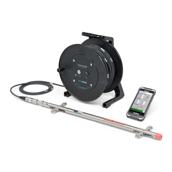
The Readout Unit, consisting of a smart phone or other Android device running the GK-604D|aos Inclinometer Readout Application (see Figure 1 and Figure 5). • The GK-604D Remote Module, housed in a weather-proof reel enclosure containing the cable that directly connects to the inclinometer probe (see Figure 1). •... -
Page 14: Features
1.1 Features Readout based on an Android device: • Users will feel familiar with the Android operating system that is common to many smart phones. • Long battery life, easily charged with micro USB cable. • Ease of use. Lightweight and simple Remote Module: •... -
Page 15: Figure 3 - Pulley Style Cable Grip
Figure 3 - Pulley style cable grip Figure 4 - Cable holds (obsolete) -
Page 16: Gk-604D | Aos
Module is fully contained within the reel as depicted in Figure 1. For users with existing analog probes that are connected through an interface unit, GK-604-4 (see Figure 7), or via the GK-604-3 reel system, the GK-604D | aos application will continue to read this discontinued hardware. -
Page 17: Compass Probes
Figure 6 - 6000/6100 type probe Figure 7 - GK-604-4 Interface 1.2.1 Compass Probes In addition to standard inclinometer probes, the GK-604D|aos can also be used with Geokon’s Digital Compass Probe. See Appendix G for more information on this probe type. -
Page 18: Before Using The Gk-604D|Aos
1.3 Before using the GK-604D|aos The readout software runs as an application under the Android operating system (minimum of 4.03) installed on a smart phone or other Android device. • The user should familiarize themselves with Android and the device running it. -
Page 19: Installation And Operation
2.1 Initial Start Sequence The following steps are a guide to the typical operation of the “GK-604D|aos” and, if followed, should result in a successful “hole” survey being taken: A) If the Remote Module has not been previously connected to the Android field device or if a new Bluetooth pairing is needed, please see section 2.2... - Page 20 If the window shown in Figure 8 is displayed, then the probe has not been previously detected by the GK-604D | aos. In this case, tapping “Yes” will cause the probe to be added to the Probe Library and the Probe Settings screen shown in Figure 9 to be displayed.
-
Page 21: Figure 8- New Probe Found
Figure 8- New Probe Found Figure 9 - Initial Probe Settings... -
Page 22: Figure 10 - No Probe Association Screen
L) Raw data files may be exported to a file system folder of the user’s choosing by tapping on “File” then “Export data to file”. See section 3.3.1.1 for more information regarding data export options. M) To close the GK-604D | aos, tap on the Android “Recent Apps” button, then dismiss the GK-604D | aos application. -
Page 23: Establishing Contact With The Remote Module
2.2 Establishing Contact with the Remote Module The procedure below should be done once for each Remote Module that the Android device will be communicating with. Follow the steps below to ensure the Bluetooth pairing with the Remote Module is established before using the readout application: 1. -
Page 24: Figure 12 - Bluetooth Pairing Screen
Figure 12 - Bluetooth Pairing Screen 3. Geokon Remote Modules typically have device names that start with “GK604DRSN” followed by the serial number of the reel. As shown in Figure 12 there is an available device called “GK604DRSN1442518”. Tap on the device to begin the pairing process (see Figure 13). -
Page 25: Figure 13 - Bluetooth Pairing Request Screen
Figure 13 - Bluetooth Pairing Request Screen Figure 14 - Paired Devices... -
Page 26: Installing The Gk-604D | Aos Application
2.3 Installing the GK-604D | aos Application The installation of the GK-604D | aos Application requires the following: • Android device with cell phone capability (and data plan) or wireless internet connection to allow access to Google Playstore. Alternatively, a USB connection from the Android device to a host PC, allowing file transfer of the application “.apk”... -
Page 27: Installing Gk-604D | Aos From Google Playstore
Google Play application (see Figure 15). Figure 15 - Google Play Store Application In Figure 15 above, enter the text, “GK-604D”, into the Google Play search bar. Selecting “GK-604D | aos Inclinometer…” from the search results screen will display the “GK-604D | aos Inclinometer App”... -
Page 28: Figure 16 - Geokon Gk-604D | Aos Install Screen
Figure 16 - Geokon GK-604D | aos Install Screen... -
Page 29: Installing Gk-604D | Aos Via Usb Link To Host Pc
2.3.2 Installing GK-604D | aos via USB link to Host PC The GK-604D | aos application can also be installed by copying an Android Application Package (.apk) file to the Android device from a host PC. The process is as follows: 1. -
Page 30: Starting The Gk-604D | Aos For The First Time
“Apps” icon followed by the “GK-604 aos” icon from the “Apps” screen. When starting the GK-604D | aos application for the first time, the screen shown in Figure 17 will be displayed. The GK-604D | aos uses “Workspaces” as the primary storage for “work”. -
Page 31: Figure 18 - Workspace Settings Screen
Figure 18 - Workspace Settings Screen After the workspace has been created, a probe library should be created in a similar fashion to the workspace. The Probe Library Settings screen is shown in Figure 19. Just as with the workspace, the probe library name is the only required parameter. The Probe Library Settings screen is saved and dismissed by tapping the “<”... -
Page 32: Figure 19 - Probe Library Settings Screen
Figure 19 - Probe Library Settings Screen For Analog Inclinometer Systems only: A probe should be created in the new probe library at this time. Tapping on the new probe library’s name in the “Probe Libraries” list causes a pop-up menu to be displayed. Tap “Select” from this menu to cause the Probes screen to be displayed. -
Page 33: Figure 20 - Workspace And Probe Library Created
Figure 20 - Workspace and Probe Library Created After dismissing the Projects Settings screen, select the new project by tapping on the new project name in the “Projects” list. Tap on “Select” from the resulting pop- up menu to cause the Holes screen to be displayed (see Figure 23). New holes can be added to the current project by tapping on the “+”... -
Page 34: Figure 21 - Select Workspace
Figure 21 - Select Workspace After saving and dismissing the Hole Settings screen, the GK-604D | aos application is nearly ready to take live readings. Please refer to section 2.1 (Initial Start Sequence), starting with step “D”. -
Page 35: Figure 22 - Projects Screen
Figure 22 - Projects Screen Figure 23 - Holes Screen... -
Page 36: Figure 24 - Hole Settings Screen
Figure 24 - Hole Settings Screen... -
Page 37: User Interface
3. User Interface 3.1 Overview The GK-604D | aos user interface contains a number of navigation controls designed to make the job of selecting application elements and functions easier. These navigation controls present an organizational view of the active workspace, inform the user about the state of the application, and provide the user with tools to configure and control Geokon devices. -
Page 38: App Menu
A more detailed description of the “APP” and “FILE” menus appear below: 3.2 APP Menu The GK-604D | aos “APP” menu provides access to high level application functionality. It is located in the upper-right corner of the main window screen (see Figure 25). -
Page 39: Live Readings
3.2.1 Live Readings Tapping on this menu item initiates the Remote Module connection process and after a successful connection, the Live Readings screen will be displayed (see Figure 30). Should the connection attempt fail, the window shown in Figure 28 will be displayed. -
Page 40: Figure 28 - Remote Module Connection Problem
1. The “Live Readings” screen is displayed ( Figure 30). 2. Figure 29 shows the message displayed if the GK-604D | aos detects temporary data left over from a previous survey that wasn’t saved. Tapping “Yes”... -
Page 41: Figure 29 - Temporary File Data Prompt
Figure 29 - Temporary File Data Prompt... -
Page 42: Figure 30 - Live Readings Screen
Figure 30 - Live Readings Screen The Live Readings screen (see Figure 30) is where all survey data points are read from the probe and stored in the application’s database. Readings are continuously updated from the Remote Module. The data set always starts with ‘Dataset 1’... -
Page 43: Figure 31 - Unsaved Data Prompt
(“Data History:” section of the screen). When done taking readings, tap “< GK-604D|aos” to dismiss the screen. The application will detect if readings have been recorded and if so, an opportunity to save the readings (see Figure 31) will be presented to the user. -
Page 44: Figure 32 - Saving Temporary Data
Figure 32 - Saving Temporary Data Figure 33 - Load Previous Data Prompt See section 3.3.5 (System Configuration) for more information about options that affect Live Readings and taking surveys. -
Page 45: Figure 34- Menu Options (Live Readings Screen)
3.2.1.1 Live Readings Screen Menu Options Figure 34 shows the available options from the Live Readings “Menu” item when a Digital Inclinometer/Compass probe is detected. These options are described below: Figure 34- Menu Options (Live Readings screen) -
Page 46: Figure 35 - Live Readings Menu Options (Compass Enabled)
Enable /Disable For GK-604D systems with a reel firmware Compass Survey version of V2.7 (or greater) AND a probe firmware version of V2.7 (or greater), the capability exists to take a Compass Survey of the selected hole at the same time as the inclinometer survey. -
Page 47: Figure 36 - Viewing Compass Data
Calibrate Compass Tapping this item causes the Compass Calibration dialog to be displayed where a procedure to calibrate the Digital Inclinometer/Compass probe can be followed. This menu item is only shown if a compass probe is detected. See Appendix G for a complete description of the Compass Calibration procedure. -
Page 48: Figure 38 - View Previous Survey
View Previous Survey Allows viewing (and loading) of previous survey Data data. When tapped, the user must first select the previous survey to view. After selecting a survey, the screen shown Figure 38 will be displayed. After dismissing this window by tapping “<”, a prompt is displayed asking the user if they’d like to load this survey. -
Page 49: Figure 39 - Meta Data Editor
Figure 39 - Meta Data Editor Figure 40 - Meta Data Editor (Screen 2) -
Page 50: Terminal Window
3.2.2 Terminal Window This feature requires an active connection to a Remote Module and will attempt to connect when invoked. If a connection cannot be made, the window shown in Figure 28 will be displayed. If a connection can be made, the window shown in Figure 41 is displayed. Using the “Terminal Window”... -
Page 51: About Gk-604D
(see Figure 27). Figure 42 - About GK-604D IRA Tapping on the “OK” icon from the reminder prompt causes the GK-604D | aos app to initiate the connection process with the Remote Module. If the connection is successful then the screen shown in Figure 43 is displayed, giving... -
Page 52: Figure 43 - Remote Module/Probe Status
Figure 43 - Remote Module/Probe Status Figure 43 depicts the status available for a digital Remote Module and probe. For analog systems, only the Remote Module version and battery voltage is listed. -
Page 53: System Configuration
3.2.4 System Configuration This screen allows selecting options that affect how the system works and how surveys are taken (see Figure 44). The sub-sections that follow describe each parameter in detail. Figure 44 - System Configuration... -
Page 54: Figure 45 - Unstable Indication
3.2.5.1 Stable Indication: Valid choices for this selection include: None On the Live Readings Screen, the only indication of stability will be to monitor the A and B readings (see Figure 30). Visual Only When this stability indication is selected the “Record” button is displayed on the Live Readings Screen in the color green if the reading is stable (Figure 30) or in the color red if the reading is unstable (see Figure 45). - Page 55 3.3.5.2 Stability Filter: If the “Stable Indication” (see section 3.2.5.1) selection is set to something other than “None”, this parameter will be enabled and an integer number can be entered. This number is used to determine readings stability (a value less than 10 is recommended). When taking live readings, if the difference between two subsequent readings of the A and B channels are less than or equal to the “Stability Filter”...
- Page 56 Valid choices for this selection (see Figure 44) include: Nothing The survey will not be filled in and will remain unfinished. “READINGS” will be modified to reflect the actual number taken. #READINGS:5 FLEVEL, 5.0, -87, 4.5, -84, 4.0, -85, 3.5, -85, 3.0, -86,...
- Page 57 3.2.5.6 Bluetooth Connection: This parameter must be a previously paired Bluetooth device that is selected from a list of known Bluetooth devices. NOTE: A survey will not be performed and no connection will be possible to the Remote Module if this parameter is not set correctly. Please see section 2.2 (Establishing Contact with the Remote Module) for more information regarding Bluetooth pairing.
-
Page 58: File Menu
3.3 FILE Menu The GK-604D | aos “FILE” Menu provides access to importing and exporting features along with data viewing and report generation. It also is used to fully delete previously “hidden” configuration elements. It is located in the upper-right corner of the main window screen (see Figure 25). -
Page 59: Figure 47 - Survey Export Options
Figure 47 - Survey Export Options 3.3.1.1 Export Data To File The “Export Data to File” menu allows exporting of data from the current hole (as listed in the status area) to a “raw” data file. Figure 48 shows the surveys available for hole “33”. -
Page 60: Figure 48 - Survey List
Figure 48 - Survey List Figure 49 - Export Folder Selection... -
Page 61: Figure 50 - Share Via Screen
3.3.1.2 Export Data Via Email The “Export Data Via Email” menu allows exporting of survey data from the current hole (as listed in the status area) as a “raw” (.gkn) data file. This file (or files in the case of an enabled digital compass) is compressed into a “zip”... -
Page 62: Figure 51 - Email Message Screen
Figure 51 - Email Message Screen NOTE: Sending data files as an email attachment requires an active data plan or access to a WIFI connection! -
Page 63: Import Menu
3.3.2 Import Menu The Import Menu is used to import configuration element settings (see Figure 52) that were previously exported using the Windows Mobile version of the GK- 604D Inclinometer Readout Application. Tapping on “Import” from the “File Menu” (see Figure 46) causes the “Import File Selection”... -
Page 64: Figure 53 - Importing Screen
Figure 53 - Importing Screen 3.3.2.1 Hole Export File (.lvhe) A Hole Export File contains all configuration parameters for a given hole as well as all survey data from all previously taken surveys. After the import is complete, a new “Hole” will be created in the currently selected project. If a hole with the same name already exists in the currently selected project a message will be displayed and the hole import will be cancelled. - Page 65 3.3.2.3 Probe Export File (.gkpe) A Probe Export File contains all configuration parameters for a given probe. After the import is complete, a new “Probe” will be created in the currently selected probe library. If a probe with the same name already exists in the currently selected probe library, a message will be displayed and the probe import will be cancelled.
-
Page 66: View Data
3.3.3 View Data When the View Data Menu is clicked the screen displayed in Figure 54 is shown. The Select View Options screen is used to select a report type (see Figure 55), survey and report options to view as a graphical or tabular report. Figure 54 - Select View Options Screen The survey or surveys are selected from rolling lists (similar to the report type in Figure 55) and, depending on the report type selected, requires the selection... -
Page 67: Figure 55 - Report Type List
Figure 55 – Report Type List Figure 56 - View Options Screen (Selecting 2 Surveys) -
Page 68: Figure 57 - Raw Data Report
3.3.3.1 Raw Data File Report This selection will cause the selected “hole” raw data to be displayed in tabular form. Figure 57 shows the report as viewed on an Android device. The column and row data will scroll left and right and up and down so that all rows and columns can be seen. -
Page 69: Figure 58 - Axis Profile Report
3.3.3.2 Axis Profile Report Selecting this option allows viewing or saving hole profile data for the A or B axis. The profile is calculated from the magnitude of the readings at each level (see Figure 58). This report lists the profile of the casing as calculated from the bottom of the casing upward or from the top down (see the Options Screen in Figure 56). -
Page 70: Figure 59 - Axis Deflection Report
3.3.3.3 Axis Deflection Report Selecting this option allows viewing or saving hole deflection data for the A or B axis. Deflection is determined from the accumulated change in deflection between the two selected data files at each level. This report lists the deflection of the casing as accumulated from the bottom of the casing upward or from the top down (see Figure 59). -
Page 71: Figure 60 - Axis Profile Plot
3.3.3.4 Axis Profile Plot Selecting this option allows a graphical view of hole profile data and is useful for visualizing the actual installed characteristics (inclination, couplings, anomalies, etc.) of the casing. Figure 60 shows a typical profile plot. “Screen-shots” of plots may be saved in “.jpg” format. Figure 60 - Axis Profile Plot... -
Page 72: Figure 61 - Axis Deflection Plot
3.3.3.5 Axis Deflection Plot Selecting this option allows a graphical view of hole deflection data for either axis and is useful for visualizing magnitude and direction of any movement of the borehole (see Figure 61). “Screen-shots” of graphical reports may be saved in “.jpg” format”. Figure 61 - Axis Deflection Plot In addition to saving reports and plots to the Android file system, each report or plot can also be emailed as attachment to the email address specified in... -
Page 73: Delete
3.4.4 Delete This menu item allows configuration elements to be permanently deleted from the system database. Tapping “Delete” acts on the currently selected item from the configuration element screen that was displayed before pressing “File”. For example, if the “Holes” screen (see Figure 23) was displayed when the “File” menu button was tapped, the only candidate for deletion will be the currently selected hole. -
Page 74: Configuration Elements
4. Configuration Elements Each configuration element has settings that can be entered/modified. For some, like Workspace, Probe Library and Project the settings consist only of a name and description. Elements such as Holes and Probes require more configuration parameters such as English/metric units, initial level, and gage factors. These settings can be adjusted to meet the user’s needs and the specifications of the probe. -
Page 75: Hole Configuration
Select the Probe Name from the drop down list. This associates a hole with a particular probe. Select “UNKNOWN” if the probe has not yet been “found” by the GK-604D | aos system. - Hole Units The units for the hole level, interval and starting level. Select either meters or feet from the drop-down list (must match probe!). -
Page 76: Figure 63 - Hole Parameters (Screen 1)
- Get GPS Coordinates This parameter may be “hidden” below the screen of the Android device. Scroll up to expose the last two parameters (see Figure 64). This button is enabled if the “GPS Status” (above) displays “GPS Available”. If the button is enabled, tapping it will cause the application to access the GPS hardware, read the current location and populate the Latitude and Longitude parameters (described above). -
Page 77: Figure 64 - Hole Parameters (Screen 2)
Figure 64 - Hole Parameters (Screen 2) -
Page 78: Probe Configuration
4.2 Probe Configuration The Probe parameters (see Figure 65) identify and configure the analog or digital probe that is connected to the Remote Module. These parameters are described below: - Probe name Use the on-screen keyboard to enter a unique and meaningful name for the probe. -
Page 79: Figure 65 - Probe Parameters Screen
Figure 65 - Probe Parameters Screen Figure 66 - Upload Settings... -
Page 80: Project Configuration
4.3 Project Configuration The Project parameters (see Figure 67) identify the Project element. These parameters are described below: - Project Name Use the on-screen keyboard to enter a unique and descriptive project name. - Description Optional parameter. Use the on-screen keyboard to enter a brief description pertaining to the project. -
Page 81: Files, Folders And Transferring Data
5.1 File Transfer In general, the only files generated by the GK-604D | aos that might have to be transferred are the “hole” data files and/or reports. Connecting the Android device to a desktop or laptop PC using a USB cable (Type A to micro B) is straight forward and allows the user to view the Android devices storage as a flash drive on the desktop/laptop;... -
Page 82: Maintenance
This is very important and should not be neglected. Geokon recommends lubricating the wheel bearings after each use as shown below. This practice forces out any water or contaminates that may be present thus extending the service life. -
Page 83: Water Entry
6.3 Water entry One of the main causes of inclinometer problems is the failure to keep the cable and probe connectors dry. This is often caused when the cable connector is not fully tightened to the to the probe connector. This connection must be properly tightened in order to compress the O-ring in the end of the probe connector. -
Page 84: Troubleshooting
Because this is the most common problem that will likely occur, this potential error deserves a section all to itself. When the GK-604D | aos is unable to establish connection to the probe (or the Remote Module) the error dialog shown in Figure 70... - Page 85 5) The probe or cable may be damaged. If the connection attempt fails multiple times after verifying the above steps, perform a full power down and restart of the Android device and attempt to connect again through the GK-604D | aos application.
-
Page 86: Common Troubleshooting Solutions
Probe GK-604D | aos for the first time Library and Workspaces screen When adding a “Hole,” The “GK-604D | aos” app has not yet “UNKNOWN” is the only choice “discovered” the new probe or the probe for “Probe name.”... -
Page 87: Appendix A. Inclinometer Theory
APPENDIX A. Inclinometer Theory A.1. Inclinometer Theory In the geotechnical field inclinometers are used primarily to measure ground movements such as might occur in unstable slopes (landslides) or in the lateral movement of ground around on-going excavations. They are also used to monitor the stability of embankments, slurry walls, the disposition and deviation of driven piles or drilled boreholes and the settlement of ground in fills, embankments, and beneath storage tanks. -
Page 88: Figure 72 - Inclinometer Probe
2 foot (English) or .5 meter (Metric) spacing facilitate the process. The probe is then removed from the casing, rotated through 180°, replaced in the casing, lowered to the bottom of the borehole and a second set of readings (the A− set) obtained as the probe is raised at the reading interval. -
Page 89: Figure 73 - Inclinometer Survey Description
GK-603 Readout ΣL sin θ Electrical Cable Inclinometer Casing Casing Alignment (exaggerated) θ L sin Probe Borehole True Vertical θ Reading Interval Coupling Backfill Probe Guide Wheels Bottom Cap Figure 73 - Inclinometer Survey Description When all these incremental horizontal deflections are accumulated and plotted beginning at the bottom of the borehole the net result is to produce a plot of the change in horizontal deflection between the time of the initial survey and the time of any subsequent survey (see Figure 74). -
Page 90: Conducting The Survey
Turn on the Android device, turn on the Remote Module (blue light blinking) then launch the GK-604D | aos application. Tap on the “Live Readings” button (from the APP menu) and verify that the Android unit has connected to the probe. -
Page 91: Checksums And "Face Errors" On Inclinometer Probes
and, after a short pause, take another reading. Continue in this way until the top marker is reached, then remove the pulley assembly, (or cable hold), and pull the inclinometer out of the hole. Twist the probe through 180 degrees then lower it to the bottom of the hole. Tap the “Dataset 1”... -
Page 92: Effect Of "Face Error" On Reading Accuracy
A.3.1 Effect of “Face Error” on reading accuracy The “face error” or check-sum can only affect the accuracy of the readings if it affects the calibration of the probe. This is possible because the output of the probe transducer is proportional to the sine of the inclination from the vertical and the sine function is non-linear. -
Page 93: Measurement Of "Face Error
The advantage of this method lies in its simplicity and the ability to set the “face error” to zero at any time without dismantling the probe. This is the method chosen by Geokon. Another advantage of this method is that it is possible by judicious choice... -
Page 94: Conclusion
(i.e., 2 sets of readings at 180°) It has further been shown that the best method by far, for setting the “face error” to zero, is by means of the software capabilities in the inclinometer reader. This is the method chosen by Geokon. -
Page 95: Appendix B. Data File Format
APPENDIX B. Data File Format B.1 Hole Data .GKN File Format GK 604M(v1.0.1.0,01/13);2.0;FORMAT II PROJECT :myHoles HOLE NO. :newHole DATE :01/02/13 TIME :14:32:13 PROBE NO.:testProbe FILE NAME:newHole_001.gkn #READINGS:61 FLEVEL, 30.0, 1013, -1052, -380, 29.5, 945, -985, -377, 29.0, 946, -981, -346, 28.5, 945,... - Page 96 6.5, 809, -842, -450, 6.0, 802, -837, -472, 5.5, 786, -817, -464, 5.0, 776, -809, -475, 4.5, 788, -818, -468, 4.0, 777, -808, -447, 3.5, 707, -757, -435, 3.0, 707, -739, -408, 2.5, 686, -721, -407, 2.0, 647, -680, -413, 1.5, 608, -643,...
-
Page 97: Appendix C. Text Reports
APPENDIX C. Text Reports C.1 Axis Profile Data Report (.CSV) Shown as displayed in Excel, for clarity:... -
Page 98: Axis Deflection Data Report (.Csv)
C.2 Axis Deflection Data Report (.CSV) Shown as displayed in Excel, for clarity:... -
Page 99: Appendix D. Remote Module Command Structure
2. Like Note 1 but are for internal use only. 3. These commands exist only for GK-604D digital system. 4. Firmware Version (Command 4) returns the Remote Module version for analog systems and the probe firmware version for digital systems. - Page 100 Example 1: LOAD PROBE DEFAULTS Loads probe default gage parameters (calibration factors): Command: D<CR> Response: GT:70A ZR:0.0000 GF:1.0000 GO:0.0000 GT:70B ZR:0.0000 GF:1.0000 GO:0.0000 Channels VA and VB: Linear Conversion Zero Read Offset = 0 Gage Factor = 1 Gage Offset = 0 Results in digits display = 2500(Vout) Example 2: Enter Gage Parameters: Enter and store gage parameters for each axis:...
- Page 101 6001-E,126543 NOTES: The GK-604D IRA uses the serial number to determine the inclinometer probe units (metric or English) by reading the model number portion of the serial number string (the part to the left of the comma). If the model number does not contain an “-E” or a “–M” then unpredictable results may...
-
Page 102: Appendix E. Data Reduction Formulas
Initial B Axis Data in Digits (2sinθ=10000 @ 30°, 2.5sinθ=12500 @ 30°). PB+,PB− Present B Axis Data in Digits (2sinθ=10000 @ 30°, 2.5sinθ=12500 @ 30°). Calculated Digit Change for A Axis. Calculated Digit Change for B Axis. Multiplier, where: Geokon probe Sinco Probe Probe configuration 2sinθ, 2.5sinθ. Metric units, millimeters, 0.05... - Page 103 SA = ((PA+)-(PA-))/2 - ((IA+)-(IA-))/2 SB = ((PB+)-(PB-))/2 – ((IB+)-(IB-))/2 Equation E-1 Change in Digits Calculation (Deflection) CA = M × RINT × SA CB = M × RINT × SB DA = (CA × cos(ZZ))-(CB × sin(ZZ)) DB = (CA × sin(ZZ))+(CB × cos(ZZ)) Equation E-2 Deflection Calculation Note: Accumulate (Σ) DA and DB results at each depth increment (from the bottom up or the top down) to obtain the deflection change (Figure 59).
-
Page 104: Profile Calculation
A Axis Data in Digits (2sinθ=10000 @ 30°, 2.5sinθ=12500 @ 30°). B+, B− B Axis Data in Digits (2sinθ=10000 @ 30°, 2.5sinθ=12500 @ 30°). Calculated Digit Change for A Axis. Calculated Digit Change for B Axis. Multiplier, where: Geokon probe Sinco Probe Probe configuration 2sinθ, 2.5sinθ. Metric units, millimeters, 0.05... -
Page 105: Gtilt Users
E.3. GTILT Users When using GTILT with the GK-604D | aos data files, use a Probe Constant of 10000 for both English and Metric “2.0sin” probes. For 2.5sin Units (Sinco) use a Probe Constant of 12500. -
Page 106: Appendix F. Technical Specifications
APPENDIX F. Technical Specifications F.1. GK-604D Digital System Specifications Standard Range ± 30° Sensors 2 MEMS accelerometers MEMS Output Differential ± 4 VDC 6100D Probe Output Digital Data Stream Probe Resolution 24-bit System Resolution ± 0.025 mm/500 mm (± 0.0001 ft/2 ft) Accuracy ±... -
Page 107: Compass Sensor Specifications
F.1.1 Compass Sensor Specifications The following table contains specifications for the Digital Compass sensor embedded in digital inclinometer probes. Compass Sensor Anisotropic Magneto-resistive MEMS Output ± 4 VDC Compass Sensor Resolution 12 bit Remote Module Resolution 16 bit Compass Sensor Accuracy ±... -
Page 108: Analog Probe System Specifications
F.2. Analog Probe System Specifications The following table contains specifications for the analog probe system which is comprised of a probe (6100-1M or 6100-1E) and the Remote Module. The Remote Module can be either a GK-604-3 (reel system) or a GK-604-4 (probe interface). Probe Range (100% F.S.) ±... -
Page 109: Android Device Minimum Specifications
proper manner and that the casing is within 5 degrees off the vertical. Accuracy is improved by allowing the probe to reach equilibrium at each depth level before taking a reading. 5. The probe is designed for use in all casing sizes up to 85mm ID (3.34in.). The wheel diameter is 30mm. -
Page 110: Appendix G. Compass Probe Operation
G.1 Inclinometer/Compass Probe (6100D-X) As of probe firmware version V2.7, coupled with the GK-604D reel assembly (also V2.7), all digital inclinometer probes now include a 3-axis, magneto-resistive, compass sensor survey (see Figure 75). The compass sensor coupled with 2 axes of MEMS, allow a spiral survey to be performed at the same time as the inclinometer survey. - Page 111 If the probe has never been detected before, a screen similar to the one in Figure 8 will be displayed. Tap “ok” to continue and the GK-604D | aos will display a probe editing screen to allow the probe to be named (see Figure 9).
-
Page 112: Figure 76 - Compass Enable Message
Figure 76 – Compass Enable Message With the compass enabled, a survey is performed as normal (see Section 3.3.1) and the compass heading can be displayed at any level by tapping on “MENU->View Compass Data”, displaying the screen shown in Figure 77. While live compass data is being shown, “Live Inclinometer Data”... -
Page 113: Figure 77 - Live Compass Data
Figure 77 - Live Compass Data 10. When done the survey, tap the “<” to the left of the title and the “Unsaved data” prompt (see Figure 31) will be displayed. Tap “Yes” to save the inclinometer/compass survey data. 11. When exporting inclinometer surveys, data is saved into a “.gkn” file as normal while the compass survey data is saved into a “.gks”... -
Page 114: Calibrate Compass
G.1.1 Calibrate Compass For optimum accuracy, the digital inclinometer/compass probe should be calibrated for each site. The GK-604D | aos provides a dialog to facilitate this (see Section 3.2.1.1 and Figure 34). A compass survey does not need to be enabled to perform the calibration. - Page 115 Figure 79 - Calibration Routine As the instructions state, the probe should be held in an upright position and slowly rotated through at least 360 degrees. The large rotating blue “arrow” serves 2 purposes: one, it indicates to the user that the probe should be turned and two, it provides feedback that the calibration routine is still running.
-
Page 116: Compass Survey Data
G.2 Compass Survey Data GK 604M(v1.2.0.0,07/14);2.0;FORMAT II PROJECT :testProj HOLE NO. :testHole DATE :7/22/14 TIME :11:30:57 PROBE NO.:incloCompass FILE NAME:testHole_012_Compass.GKS #READINGS:71 FLEVEL, 35.0, 164, 254, 34.5, 164, 254, 34.0, 168, 258,...
Need help?
Do you have a question about the GK-604D and is the answer not in the manual?
Questions and answers