Geokon GK-604D User Manual
Inclinometer readout application
Hide thumbs
Also See for GK-604D:
- User manual (116 pages) ,
- Instruction manual (64 pages) ,
- Quick start manual (6 pages)
Table of Contents
Advertisement
GK-604D
Inclinometer Readout
Application
User's Manual
No part of this instruction manual may be reproduced, by any means, without the written consent of Geokon, Inc.
The information contained herein is believed to be accurate and reliable. However, Geokon, Inc. assumes no responsibility
for errors, omissions or misinterpretation. The information herein is subject to change without notification.
Copyright © 2014 by Geokon, Inc.
(Doc Rev H, 11/2014)
Advertisement
Table of Contents

Related Manuals for Geokon GK-604D


Summary of Contents for Geokon GK-604D
- Page 1 Application User’s Manual No part of this instruction manual may be reproduced, by any means, without the written consent of Geokon, Inc. The information contained herein is believed to be accurate and reliable. However, Geokon, Inc. assumes no responsibility for errors, omissions or misinterpretation. The information herein is subject to change without notification.
- Page 3 The buyer's sole remedy for any breach of this agreement by Geokon, Inc. or any breach of any warranty by Geokon, Inc. shall not exceed the purchase price paid by the purchaser to Geokon, Inc.
-
Page 5: Table Of Contents
1.1 Features ................... 1 1.2 GK-604D Inclinometer Readout Application ........... 3 1.2.1 Tiltmeter and Compass Probes ................5 1.3 Before using the GK-604D Inclinometer Readout ........6 2. Installation and Operation................. 7 2.1 Initial Quick Start Sequence ..............7 2.2 Establishing Contact with the Remote Module ........12 2.3 Installing the GK-604D IRA ............... - Page 6 3.4.3 View Data ........................53 3.4.4 Delete/Restore Menu ....................56 3.4.5 Exit ........................... 57 4. Configuring Project Explorer Elements ............. 58 4.1 Hole Configuration ................59 4.2 Probe Configuration ................. 60 4.3 Project Configuration ............... 62 5. Files, Folders and Transferring Data ............63 5.1 File Transfer ...................
- Page 7 E.2. Profile Calculation ................85 E.3. GTILT Users ................... 86 APPENDIX F. Technical Specifications ............87 F.1. GK-604D Digital System Specifications ..........87 F1.1 Compass Sensor Specifications ................88 F.2. Analog Probe System Specifications ..........89 F.3. Field PC (FPC-1) Specifications ............90 APPENDIX G.
- Page 8 Figure 13 - Hand-held device root folder contents ................18 Figure 14 - Installation Folder Contents ....................18 Figure 15 - GK-604D Installer at root of HDD ..................19 Figure 16 - GK-604D Install Screen ....................... 20 Figure 17 - GK-604D IRA Icon in Start->Program .................. 20 Figure 18 - Select Workspace Name .....................
- Page 9 Figure 34 - Viewing Inclinometer Data ....................33 Figure 35 - Viewing Compass Data....................... 34 Figure 36 - Terminal Window ......................35 Figure 37 - About GK-604D IRA ......................37 Figure 38 - Ready for Connection?....................... 37 Figure 39 - Remote Module/Probe Status ................... 38 Figure 40 - System Configuration ......................
- Page 10 Figure 56 - Select Probe Library Export File Figure 57 - Probe Library Switch after Import ..... 52 Figure 58 - Select View Options Window Figure 59 - View Option List ........... 53 Figure 60 - Menu Options for Reports Figure 61 - Raw Data Report ..........
- Page 11 Figure 88 – Compass Enable Message ....................101 Figure 89 - Live Compass Data ......................102 Figure 90 - Initial Calibration Screen ....................103 Figure 91 - Calibration Routine ......................104...
-
Page 13: Introduction
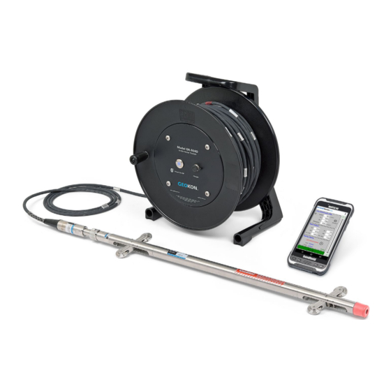
1. Introduction The GK-604D is made up of three components: • the Readout Unit, consisting of a hand-held field PC running the GK-604D Inclinometer Readout Application (see Figures 1 and 3). • the GK-604D Remote Module, housed in a weather-proof reel enclosure containing the cable that directly connects to the inclinometer probe (see Figures 1 and 6) •... -
Page 14: Figure 2 - Model 6000-2 Control Cable (Top)
Lightweight and simple Remote Module: lithium battery (8 + hours of continuous use) • • one button operation; automatic power down when Bluetooth connection is dropped or after several minutes of inactivity • rugged • reliable connection to standard inclinometer probes (Figures 1 and 4) is accomplished via model 6000-2 control cable which features a lightweight, polyurethane jacket and is less than 7 mm in diameter (see Figure 2). -
Page 15: Gk-604D Inclinometer Readout Application
1.2 GK-604D Inclinometer Readout Application The GK-604D Inclinometer Readout Application (GK-604D IRA) installs and runs on a ruggedized hand-held PC (FPC-1) (see Figure 3) and is designed to communicate via Bluetooth with Remote Modules connected to analog or digital probes (see Figure 4), both MEMS and force-balance type. -
Page 16: Figure 4 - 6000/6100 Type Probe
Figure 4 - 6000/6100 type probe Figure 5 - GK-604-4 Interface... -
Page 17: Tiltmeter And Compass Probes
Archer Field PC from Juniper Systems (shown in Figure 6) as well as the newer Archer2. 1.2.1 Tiltmeter and Compass Probes In addition to standard inclinometer probes, the GK-604D IRA also can be used with Geokon Tiltmeter and Compass Probes. See Appendices G and H for more information on these probe types. -
Page 18: Before Using The Gk-604D Inclinometer Readout
1.3 Before using the GK-604D Inclinometer Readout The readout software runs as an application under Windows Mobile 6 operating system installed on a hand-held PC (FPC-1). • The user should familiarize themselves with the FPC-1 and the Windows Mobile •... -
Page 19: Installation And Operation
The steps described in section 2.1 are an attempt to guide the user through the process of launching the GK-604D IRA, connecting to the probe and taking a survey. If all parts of the GK-604D are purchased as a system, Geokon makes every effort to ensure that the system is completely set up and working before it leaves the factory. - Page 20 E) If the Inclinometer System is a digital system (probe model numbers 6100D-E and 6100D-M), any new “probe” will be discovered upon connection to the Remote Module (covered in later steps). F) If launching the GK-604 IRA for the first time, a “project” and a “hole” must be defined before connecting to the Remote Module (see sections 3.2, 4.4 and 4.1 for more information regarding adding and configuring Project Explorer elements).
-
Page 21: Figure 7 - Probe Settings Mismatch
b. The Live Readings Window will be displayed (see Figure 29). This indicates that the GK-604 IRA has recognized the probe as one it has connected to before. Figure 7 - Probe Settings Mismatch... -
Page 22: Figure 8 - Initial Probe Settings
Figure 8 - Initial Probe Settings Figure 9 - No probe association window I) Refer to section 3.3.1 for more information about taking a survey using the Live Readings window. Also refer section A.2 for information regarding the... - Page 23 K) Raw data files may be exported to a file system folder of the user’s choosing by tapping on “File”, then “Export”, then “Data”. See section 3.4.1.1 for more information regarding data export options. L) To close the GK-604D IRA, tap “File” then “Exit”.
-
Page 24: Establishing Contact With The Remote Module
“Mode” tab and then make sure that the box next to “Turn on Bluetooth” is checked. 3. Click on the “Devices” tab. If it shows a “Geokon” device (name will start with “GK604” and contain the remote’s serial number), go to step 6. Otherwise turn on the remote module (should see a flashing blue indicator on the remote) and select “Add new device…”. - Page 25 Bluetooth Devices screen. 6. Click on the COM Ports tab. If the “Geokon” device is already assigned to a COM Port, skip to step 9. If no COM port is assigned, select “New Outgoing Port”.
- Page 26 The screen-shot to the right shows the devices that a COM Port may be selected for. Select the appropriate “Geokon” device from the list and tap “Next”. 8. From the “Port:” drop-down list, select a COM port (COM5 is the default). Be sure to remember the number of the COM port as you may have to select it later in the readout software (see sections 3.3.1 and...
-
Page 27: Installing The Gk-604D Ira
Bluetooth connection to a COM port. Windows .NET 3.5 Compact Framework (CF) and .NET framework English-language Messages package installed on HHD. Both “CAB” file installers are included in the GK-604D IRA installer “Zip” file, available on Geokon’s web-site (http://www.geokon.com/digital-inclinometer-system/). -
Page 28: Figure 11 - Windows Mobile Device Center
Figure 11 - Windows Mobile Device Center... -
Page 29: Launching The Gk-604D Installer
2.3.1 Launching the GK-604D Installer From the Windows Mobile Device Center window on a desktop PC (see Figure 11) click on the folder icon labeled “Browse the contents of your device” to call up an Explorer Window for the HHD (see Figure 12). The procedure for ActiveSync is very similar. -
Page 30: Figure 13 - Hand-Held Device Root Folder Contents
Figure 13 - Hand-held device root folder contents Next, unzip the GK-604D Installer (downloaded from Geokon’s web-site), open a Windows Explorer window and then navigate to the root folder of the Installation folder (see Figure 14). Figure 14 - Installation Folder Contents... -
Page 31: Figure 15 - Gk-604D Installer At Root Of Hdd
Explorer (see Figure 15) and tap the file, “GK604D_Installer” to execute the installer. Figure 15 - GK-604D Installer at root of HDD If there is a storage card installed in the HHD then the user will be prompted to choose the location for the installation (see Figure 16). It is recommended that “Device”... -
Page 32: Figure 16 - Gk-604D Install Screen
Figure 16 - GK-604D Install Screen The file, GK604D_Installer.CAB can be now deleted from the system root folder to free up memory. The GK-604D IRA is now installed and its icon should appear in “Start->Programs” (see Figure 17). Figure 17 - GK-604D IRA Icon in Start->Program... -
Page 33: Starting The Inclinometer Readout The First Time
Windows Mobile devices, this folder is located at: \Application Data\Geokon\GK-604D\Workspaces GK-604D IRA appends the name of the new workspace to this shared folder and uses it as the default location for the new workspace. The user is free to select their... -
Page 34: Figure 19 - Select Workspace Folder
Note: If the newly selected workspace folder contains an existing workspace, GK-604D IRA will display a dialog prompt asking the user if they want to import the workspace as is or to rename it with the previously specified new workspace name. -
Page 35: Figure 21 - Select Probe Library Name
For Windows Mobile devices this folder is located at: \Application Data\Geokon\GK-604D\Probe Libraries GK-604D IRA appends the name of the new probe library to this shared folder and uses it as the default location for the new probe library. The user is free to select their own location, either by entering it directly, or the Browse [ …... -
Page 36: Figure 22 - Select Probe Library Folder
Note: If the newly selected probe library folder contains an existing probe library, GK-604D IRA will display a dialog prompt asking the user if they want to import the probe library as is or to rename it with the previously specified new workspace name. -
Page 37: Figure 24 - Empty Workspace And Probe Library
After the initial workspace and probe library are created the GK-604D IRA will open with the newly created workspace and probe library displayed (see Figure 24). New project(s) and hole configurations may be added to your workspace as well as adding new probes (settings) to the new probe library. -
Page 38: User Interface
3. User Interface 3.1 Overview The GK-604D IRA user interface contains a number of navigation controls designed to make job of selecting application elements and functions easier. These navigation controls present an organizational view of the active workspace, inform the user about the state of the application, and provide the user with tools to configure and control Geokon devices. -
Page 39: Project Explorer
3.2 Project Explorer The Project Explorer is the primary navigation mechanism for moving around the GK-604D IRA workspace and probe library. The Project Explorer presents a view of the workspace including projects and holes and a view of the probe library that includes available probes. -
Page 40: Context Menu
3.2.1 Context Menu From the Project Explorer, new workspace elements can be added using the context menu. Access the drop-down menu by tapping and holding the explorer element that is to be operated on. The context menu is context sensitive in that, based on the current selection, the appropriate elements will be enabled and others will be disabled. -
Page 41: Application Menu
3.3 Application Menu The GK-604D IRA Application Menu provides access to high level application functionality. It is located in the lower, right corner of the main window frame. The “Edit Settings” menu sub-item of this menu can also be accessed via the context menu. -
Page 42: Figure 28 - Remote Module Connection Problem
Figure 28 - Remote Module Connection Problem After the Remote Module successfully connects to the FPC-1, the blue “POWER ON” indicator will transition from blinking to steadily lit and the “Live Readings” screen is displayed (Figure 29). • Readings are continuously updated from the Remote Module. -
Page 43: Figure 30 - Unsaved Data Prompt
• A “beep” sound should be heard, confirming that the reading has been stored. If no beep is heard, tap the “volume” control at the top of the screen and adjust the volume. • Be sure to move the probe to the new level and wait for the readings to stabilize before recording the next reading. -
Page 44: Figure 32 - Save File Screen
Figure 32 - Save File Screen See section 3.3.5 (System Configuration) for more information about options that affect Live Readings and taking surveys. 3.3.1.1 Live Readings Screen Menu Options Figure 33 shows the available options from the Live Readings “Menu” item when a Digital Inclinometer/Compass probe is detected. -
Page 45: Figure 34 - Viewing Inclinometer Data
Enable Compass Survey For GK-604D systems with a reel firmware version of V2.7 (or greater) AND a probe firmware version of V2.7 (or greater), capability exists to take a Compass Survey of the selected hole at the same time as the inclinometer survey. -
Page 46: Figure 35 - Viewing Compass Data
Figure 35 - Viewing Compass Data... -
Page 47: Edit Settings
3.3.2 Edit Settings As with the Context Menu (see section 3.2.1), tapping the “Edit Settings” menu will invoke the Settings Editor for the currently selected Project Explorer element (See the section 4 for more information on settings). 3.3.3 Terminal Window This feature requires an active connection to a Remote Module and will attempt to connect when invoked. - Page 48 Alternately, tapping the “Send” menu gives the user the ability to send a character to the Remote Module with or without a Carriage Return (CR) appended to the character string (see Figure 36). This is useful when a confirmation character is required (such as for the calibration routine) but no carriage return.
-
Page 49: About Gk-604D
Module and is the Remote Module ready to connect (blue light blinking) (see Figure 38). Figure 37 - About GK-604D IRA Figure 38 - Ready for Connection? Tapping on the “Yes” button causes the GK-604D IRA to initiate the connection... -
Page 50: Figure 39 - Remote Module/Probe Status
process with the Remote Module. If the connection is successful then the following is displayed (see Figure 39), giving status about the Remote Module Figure 39 - Remote Module/Probe Status Figure 39 depicts the status available for a digital Remote Module and probe. For analog systems, only the Remote Module version and battery voltage is listed. -
Page 51: System Configuration
3.3.5 System Configuration This screen allows selecting options that affect how the system works and how a survey is taken (see Figure 40). The sub-sections that follow describe each parameter in detail. Figure 40 - System Configuration 3.3.5.1 Stable Indication Valid choices for this selection include: None On the Live Readings Screen, the only indication of... -
Page 52: Figure 41 - Stable Indication
Figure 41 - Stable Indication Figure 42 - Unstable Indication... - Page 53 3.3.5.2 Stability Filter If the “Stable Indication” (see section 3.3.5.1) selection is set to something other than “None”, this parameter will be enabled and a drop-down list will facilitate the entry of a number that is used to determine readings stability (a value less than 10 is recommended).
-
Page 54: Figure 43 - Auto Record Enabled
Figure 43 – Auto Record Enabled To activate the “Auto Record” feature, tap on the “Play” icon to the right of the “A” reading text box. The “Play” icon will be replaced with the “Pause” icon, the red text status message will change to “Auto record mode is active”... - Page 55 The list of steps below illustrates the proper way to utilize the “Auto Record” feature. For the purpose of this example the following is assumed: • the hand-held device is connected via Bluetooth to the Remote Module • in System Configuration, the “Stable Indication” parameter is set to “Visual/Audible”...
-
Page 56: Figure 45 - Auto Record Paused, Dataset 2 Selected
Tap the “Dataset 1” icon and observe that the red status text message will change to “Auto record mode is paused” and the “Pause” icon will change to the “Play” icon while “Dataset 1” becomes “Dataset 2” (see Figure 42). Figure 45 - Auto record paused, Dataset 2 selected After rotating the probe 180 degrees, lower it back to the “Starting Level”... - Page 57 NOTE: An “Auto Record” survey can be paused at any time and re- started as long as the probe is moved to the proper level reflected by the “Level:” display. When an Auto Record survey is paused, the data can still be recorded in the “normal” fashion by tapping on the “Record Data”...
- Page 58 Blanks Each missing level “row” of the survey will be filled in with blank characters #READINGS:11 FLEVEL, 5.0, -86, 4.5, -86, 4.0, -86, 3.5, -86, 3.0, -86, 2.5, -86, 2.0, 1.5, 1.0, 0.5, 0.0,...
-
Page 59: File Menu
3.4 File Menu The file menu is used to import and export Project Explorer element settings along with data export, viewing and report generation. It also is used to fully delete and/or restore previous deleted Project Explorer elements (see Figure 46). Figure 46 - File Menu Figure 47 - Export Menu 3.4.1 Export Menu... -
Page 60: Figure 48- Export Data Window Figure 49 - Save Data File
Figure 48- Export Data Window Figure 49 - Save Data File 3.4.1.2 Export Hole Settings Clicking on this menu item displays the “Select Export Path” window (see Figure 50), from which a path to export the hole settings file can be selected. -
Page 61: Figure 50 - Export Path Selection Figure 51 - Probe Selection Window
3.4.1.5 Export Probe Library Clicking on this menu item displays the “Select Export Path” window (see Figure 50), from which a path to export the probe library files can be selected. All files and folders within the probe library are compressed into a single export file. -
Page 62: Import Menu
3.4.2 Import Menu The Import Menu is used to import Project Explorer element settings (see Figure 52) that were previously exported using the Export Menu functions (see Figure 47). 3.4.2.1 Import Hole Settings Clicking on this menu item displays the “Select .LVHE File” window (see Figure 53), from which a hole export file can be selected (see section 3.4.1.2). -
Page 63: Figure 54 - Select Project Export File Figure 55 - Select Probe Export File
3.4.2.3 Import Probe Settings Clicking on this menu item displays the “Select .GKPE File” window (see Figure 55), from which a probe export file can be selected (see section 3.4.1.4). After selection, a new “Probe” will be created in the current probe library. -
Page 64: Figure 56 - Select Probe Library Export File Figure 57 - Probe Library Switch After Import
3.4.2.4 Import Probe Library Clicking on this menu item displays the “Select .GPLE File” window (see Figure 56), from which a probe library export file can be selected (see section 3.4.1.5). After selection, a message query will be displayed (see Figure 57) asking the user if they would like to make the imported probe library the current one. -
Page 65: View Data
3.4.3 View Data When the View Data Menu is clicked the screen displayed in Figure 58 is shown. The Select View Options screen is used to select a view option (see Figure 59) and data files to view a graphical or tabular report. Figure 58 - Select View Options Window Figure 59 - View Option List The available “View”... -
Page 66: Figure 60 - Menu Options For Reports Figure 61 - Raw Data Report
Figure 60 - Menu Options for Reports Figure 61 - Raw Data Report Figure 62 - Axis Profile Report Figure 63 - Axis Deflection Report 3.4.3.3 Axis Deflection Data as Table Selecting this option allows viewing or saving hole deflection data for the A or B axis. -
Page 67: Figure 64 - Profile Plot Figure 65 - Profile Plot - Marker On
deflection between the two selected data files at each level. This report lists the deflection of the casing as accumulated from the bottom of the casing upward or from the top down (see Figure 63). See Appendix C for an example of a deflection report saved in text form. Tabular reports may be saved in comma-separated value (.csv) or “Text”... -
Page 68: Delete/Restore Menu
A special folder is reserved for storing project explorer elements that are deleted from a workspace. Tapping the Delete/Restore menu causes the GK-604D IRA to search this folder to see which elements are available for restoring or permanent deletion. As can... -
Page 69: Exit
Figure 67 - Delete / Restore Window Figure 68 - Hole Delete / Restore Window 3.4.5 Exit Tapping on this menu item will cause the program to cease execution. -
Page 70: Configuring Project Explorer Elements
4. Configuring Project Explorer Elements Each project explorer element has settings that can be configured. For some, like Workspace, Probe Library and Project the settings consist only of a name and description. Elements such as Holes and Probes require more configuration parameters such as English/metric units, initial level, and gage factors. -
Page 71: Hole Configuration
4.1 Hole Configuration Figure 69 depicts the Hole General Settings, the first screen of the Edit Hole Settings dialog: Hole ID Read-only value, generated when the hole was created. Used internally by the GK- 604D IRA. Hole name Tap on the keyboard icon (bottom of the screen) to bring up the on-screen keyboard. -
Page 72: Probe Configuration
Figure 71 depicts the General Probe Settings, the first screen of the Edit Probe Settings dialog: - Probe ID Read-only value, generated when the probe was created. Used internally by the GK-604D IRA. - Serial number Read-only parameter for digital inclinometer probes, read/write parameter for analog and compass probes. - Page 73 - A and B Channel Zero Shift To compensate for any offset at zero enter appropriate values for the Zero Shift values (see the Inclinometer Probe manual and Calibration sheet for more information). Digital probes may have these values programmed at the factory. When the probe type is set to Compass, the Zero Shift A value should be set to 200 (see Figure 72).
-
Page 74: Project Configuration
4.3 Project Configuration Figure 73 depicts the Projects Settings dialog: - Project ID Read-only value, generated upon project creation. Used internally by the GK-604D IRA. - Project Name Use the on-screen keyboard to enter a unique and descriptive project name. -
Page 75: Files, Folders And Transferring Data
5. Files, Folders and Transferring Data The GK-604D IRA uses several types of files and dedicated folder locations to keep track of Workspaces and Project Explorer element configuration files, such as hole and probe configuration files and data files. The default locations and names for most of these... -
Page 76: File Transfer
5.1 File Transfer In general, the only files generated by the GK-604D IRA that will have to be transferred are the “hole” data files, although periodically archiving others on a “master” PC is recommended. Connecting the Field PC to a desktop or laptop PC using the supplied USB cable (Type A to mini B) is straight forward and allows the user to view the Field PC’s storage as a flash drive on the desktop/laptop;... -
Page 77: Appendix A. Inclinometer Theory
APPENDIX A. Inclinometer Theory A.1. Inclinometer Theory In the geotechnical field inclinometers are used primarily to measure ground movements such as might occur in unstable slopes (landslides) or in the lateral movement of ground around on-going excavations. They are also used to monitor the stability of embankments, slurry walls, the disposition and deviation of driven piles or drilled boreholes and the settlement of ground in fills, embankments, and beneath storage tanks. -
Page 78: Figure 75 - Inclinometer Probe
Cable Cable Fitting Wheel Assembly Accelerometer Housing Wheel Assembly Bottom Cushion Figure 75 - Inclinometer Probe Inclinometer probes usually contain two accelerometers with their axes oriented at 90° to each other. The A axis is in line with the wheels (Figure 75 illustrates) with the B axis orthogonal to it. -
Page 79: Figure 76 - Inclinometer Survey Description
GK-603 Readout ΣL sin θ Electrical Cable Inclinometer Casing Casing Alignment (exaggerated) θ L sin Probe Borehole True Vertical θ Reading Interval Coupling Backfill Probe Guide Wheels Bottom Cap Figure 76 - Inclinometer Survey Description When all these incremental horizontal deflections are accumulated and plotted beginning at the bottom of the borehole the net result is to produce a plot of the change in horizontal deflection between the time of the initial survey and the time of any subsequent survey (see Figure 77). -
Page 80: Conducting The Survey
Switch on the FPC-1, turn on the Remote Module (blue light blinking) then launch the GK-604D IRA. After verifying that the hand-held unit has connected to the probe, click on the “Live Readings” menu and observe the inclinometer reading. -
Page 81: Checksums And "Face Errors" On Inclinometer Probes
Make sure that the GK-604D IRA is set to Data Set 1.Take the first reading, pull up on the cable until the next cable marker sits in the cable hold and, after a short pause, take another reading. Continue in this way until the top marker is reached, remove the cable hold, pull the inclinometer out of the hole. -
Page 82: Effect Of "Face Error" On Reading Accuracy
A.3.1 Effect of “Face Error” on reading accuracy The “face error” or check-sum can only affect the accuracy of the readings if it affects the calibration of the probe. This is possible because the output of the probe transducer is proportional to the sine of the inclination from the vertical and the sine function is non-linear. -
Page 83: Measurement Of "Face Error
A.3.2 Measurement of “Face Error” The “face error” is the reading shown by the inclinometer probe when it is perfectly vertical. In practice , the easiest way to obtain the “face error” is to run a normal inclinometer survey, with the two sets of readings at 180 °, and then to run a profile or deflection report. -
Page 84: Conclusion
(i.e.2 sets of readings at 180°) It has further been shown that the best method by far, for setting the “face error” to zero, is by means of the software capabilities in the inclinometer reader. This is the method chosen by Geokon. -
Page 85: Appendix B. Data File Format
APPENDIX B. Data File Format B.1 Hole Data File Format GK 604M(v1.0.1.0,01/13);2.0;FORMAT II PROJECT :myHoles HOLE NO. :newHole DATE :01/02/13 TIME :14:32:13 PROBE NO.:testProbe FILE NAME:newHole_001.gkn #READINGS:61 FLEVEL, 30.0, 1013, -1052, -380, 29.5, 945, -985, -377, 29.0, 946, -981, -346, 28.5, 945, -978,... - Page 86 7.5, 785, -819, -441, 7.0, 811, -844, -456, 6.5, 809, -842, -450, 6.0, 802, -837, -472, 5.5, 786, -817, -464, 5.0, 776, -809, -475, 4.5, 788, -818, -468, 4.0, 777, -808, -447, 3.5, 707, -757, -435, 3.0, 707, -739, -408, 2.5, 686, -721,...
-
Page 87: Appendix C. Text Reports
APPENDIX C. Text Reports C.1 Raw Data Text Report Hole Survey Raw Data Report ---------------------------------------------------------------- Project Name: myHoles Hole Name: newHole Top Elevation: 186.6 File Name: newHole_001.gkn Reading Date: 01/02/13 Reading Time: 14:32:13 Probe Name: testProbe ---------------------------------------------------------------- Level Elev. (dig.) (dig.) (dig.) (dig.) (m) ---------------------------------------------------------------- -600 -361... -
Page 88: A-Axis Profile Data Text Report
25.5 1042 -1075 -415 161.1 1037 -1075 -376 160.6 26.5 1046 -1078 -348 160.1 1034 -1068 -316 159.6 27.5 1014 -1050 -318 159.1 -1048 -337 158.6 28.5 -978 -331 158.1 -981 -346 157.6 29.5 -985 -377 157.1 1013 -1052 -380 156.6 C.2 A-axis Profile Data Text Report Report: A-Axis Digits and Profile in Centimeters (Bottom Up) -
Page 89: B-Axis Profile Data Text Report
165.6 1047 -1082 2129 1065 49.55 165.1 1080 -1116 2196 1098 46.89 21.5 164.6 1099 -1131 2230 1115 44.15 164.1 1029 -1063 2092 1046 41.36 22.5 163.6 1020 -1054 2074 1037 38.74 163.1 1024 -1061 2085 1043 36.15 23.5 162.6 1027 -1066 2093... -
Page 90: A-Axis Deflection Data Text Report
171.1 -566 -1072 -536 -32.45 15.5 170.6 -567 -1064 -532 -31.11 16 170.1 -545 -1038 -519 -29.78 16.5 169.6 -549 -1049 -524 -28.48 17 169.1 -541 -1024 -512 -27.17 17.5 168.6 -572 -1085 -542 -25.89 18 168.1 -553 -1043 -521 -24.53 18.5 167.6 -551... -
Page 91: B-Axis Deflection Data Text Report
177.1 -802 1568 -857 1568 -.09 176.6 -789 1543 -845 1544 -.09 176.1 -785 1537 -840 1522 -.09 10.5 175.6 -789 1544 -844 1542 -.07 175.1 -808 1586 -865 1585 -.07 11.5 174.6 -836 1636 -892 1638 -.06 174.1 -874 1715 -929 1711... - Page 92 183.1 -435 -810 -434 -810 182.6 -447 -828 -447 -829 182.1 -468 -872 -468 -872 181.6 -475 -887 -474 -885 181.1 -464 -862 -464 -870 180.6 -472 -886 -469 -880 180.1 -450 -844 -450 -843 179.6 -456 -844 -454 -840 179.1 -441 -827...
-
Page 93: Appendix D. Remote Module Command Structure
2. Like Note 1 but are for internal use only. 3. These commands exist only for GK-604D digital system. 4. Firmware Version (Command 4) returns the Remote Module version for analog systems and the probe firmware version for digital systems. - Page 94 6001-E,126543 NOTES: The GK-604D IRA uses the serial number to determine the appropriate probe units (metric or english) by reading the model number portion of the serial number string (the part to the left of the comma). If the model number does not contain a “-E” or a “–M” then unpredictable results may occur.
-
Page 95: Appendix E. Data Reduction Formulas
Initial B Axis Data in Digits (2sinθ=10000 @ 30°, 2.5sinθ=12500 @ 30°). PB+,PB− Present B Axis Data in Digits (2sinθ=10000 @ 30°, 2.5sinθ=12500 @ 30°). Calculated Digit Change for A Axis. Calculated Digit Change for B Axis. Multiplier, where: Geokon probe Sinco Probe Probe configuration 2sinθ, 2.5sinθ. Metric units, millimeters, 0.05... - Page 96 SA = ((PA+)-(PA-))/2 - ((IA+)-(IA-))/2 SB = ((PB+)-(PB-))/2 – ((IB+)-(IB-))/2 Equation E-1 Change in Digits Calculation (Deflection) CA = M × RINT × SA CB = M × RINT × SB DA = (CA × cos(ZZ))-(CB × sin(ZZ)) DB = (CA × sin(ZZ))+(CB × cos(ZZ)) Equation E-2 Deflection Calculation Note: Accumulate (Σ) DA and DB results at each depth increment (from the bottom up or the top down) to obtain the deflection change (Figure 66).
-
Page 97: Profile Calculation
A Axis Data in Digits (2sinθ=10000 @ 30°, 2.5sinθ=12500 @ 30°). B+, B− B Axis Data in Digits (2sinθ=10000 @ 30°, 2.5sinθ=12500 @ 30°). Calculated Digit Change for A Axis. Calculated Digit Change for B Axis. Multiplier, where: Geokon probe Sinco Probe Probe configuration 2sinθ, 2.5sinθ. Metric units, millimeters, 0.05... -
Page 98: Gtilt Users
E.3. GTILT Users When using GTILT with the GK-604D use a Probe Constant of 10000 for both English and Metric probes when using 2.0sin Units! For 2.5sin Units use a Probe... -
Page 99: Appendix F. Technical Specifications
APPENDIX F. Technical Specifications F.1. GK-604D Digital System Specifications Standard Range ± 30° Sensors 2 MEMS accelerometers MEMS Output Differential ± 4 VDC 6100D Probe Output Digital Data Stream Probe Resolution 24-bit System Resolution ± 0.025 mm/500 mm (± 0.0001 ft/2 ft) Accuracy ±... -
Page 100: F1.1 Compass Sensor Specifications
F1.1 Compass Sensor Specifications The following table contains specifications for the Digital Compass sensor embedded in digital inclinometer probes. Compass Sensor Anisotropic Magnetoresistive MEMS Output ± 4 VDC Compass Sensor Resolution 12 bit Remote Module Resolution 16 bit Compass Sensor Accuracy ±... -
Page 101: Analog Probe System Specifications
F.2. Analog Probe System Specifications The following table contains specifications for the analog probe system which is comprised of a probe (6100-1M or 6100-1E) and the Remote Module. The Remote Module can be either a GK-604-3 (reel system) or a GK-604-4 (probe interface). Probe Range (100% F.S.) ±... -
Page 102: Field Pc (Fpc-1) Specifications
improved by allowing the probe to reach equilibrium at each depth level before taking a reading. 5. The probe is designed for use in all casing sizes up to 85mm ID (3.34in.). The wheel diameter is 30mm. The cable connector adds 150mm to the length of the probe. F.3. -
Page 103: Appendix G. Tiltmeter Operation (Model 6101)
APPENDIX G. Tiltmeter Operation (Model 6101) When connected to the GK-604-4 Probe Interface Module (see Figure 5), the Model 6101 Tiltmeter (see Figure 78) can be read with the FPC-1 using the GK-604D IRA. Figure 78 - Model 6101 Tiltmeter with 6201-3 Interface Cable... -
Page 104: Figure 79 - Tiltplates: 6201-1C (Ceramic), 6201-1A (Copper Plated Aluminum), 6201-1S (Stainless)
1. Connect one end of the 6201-3 cable to the Tiltmeter 2. Connect the other end of the 6201-3 cable to the GK-604-4 Interface Module. 3. On the FPC-1, launch the GK-604D IRA and create a new probe configuration: Using the Context Menu (see section 3.2.1), after highlighting the Probe •... - Page 105 GO = Gage Offset A [from probe configuration – usually zero (0)] DIGITS = ((R1 – R0) * GF) + GO ≈ Volts PV = (R1 – R0) / 2000 [for Geokon probes: +4V +15 degrees] DEGREES = arcsin( ((R1 – R0) / 20000) * GF ) [multiply by 180/Pi Degrees...
-
Page 106: Figure 80 - Live Readings (Tiltmeter)
Figure 80 - Live Readings (Tiltmeter) 8. Align the Tiltmeter on the tiltplate in the A+ orientation, then tap “Record Data” to take the “A+” reading. 9. Tap the “Dataset” icon and observe that the dataset number changes to “2”. Reverse the Tiltmeter orientation to A- and, again, tap “Record Data”... -
Page 107: Figure 82 - Save File Dialog
11. Tap the “Yes” button to start the data saving process. The “Save File” dialog will be displayed, allowing the user to name the data file to save (see Figure 82). Figure 82 - Save File Dialog 12. After tapping “Save” the GK-604 IRA will determine if the file exists. If this is a new file then the data will be written to it in a format similar to the standard Inclinometer format. -
Page 108: Tiltmeter Data Format
13. Tapping “Yes” on the “File exists” dialog allows multiple reads for this location to be stored in a single data file. See section G.1 for an example of Tiltmeter data format. 14. Tapping “No” at the “File exists” dialog will again call up the “Save File” dialog (see Figure 82) and another opportunity will be given to select a new file. -
Page 109: Appendix H. Spiral And Compass Probe Operation
System or the GK-604-4 Interface Module. 2) The digital Inclinometer/Compass Probe (6100D-X, Firmware Version V2.5), requiring a GK-604D-X Digital Reel System with a firmware version of V2.5 or higher. While both probes can provide spiral survey data, there are significant differences in their features and operation. -
Page 110: Figure 85 - Live Readings For Spiral Data
Remote Module and the FPC-1 Field PC. See Section 2.2 for more information regarding Bluetooth pairing. Launch the GK-604D IRA. Create a new probe in the Probe Library and configure it for a probe type of “Compass”. -
Page 111: Figure 86 - Saving Compass Survey Data
Unlike an inclinometer survey, a spiral survey only requires A+ data so a second pass is not necessary (do not tap Dataset after first pass). When done the survey, tap “Menu->Exit Live Readings” and the screen shown in Figure 86 will be displayed. Tap “Yes” to save the compass survey data. Figure 86 - Saving Compass Survey Data The survey data is saved into a “.gkn”... -
Page 112: Inclinometer/Compass Probe (6100D-X)
H.2 Inclinometer/Compass Probe (6100D-X) As of probe firmware version V2.5, coupled with the GK-604D reel assembly (also V2.5), all digital inclinometer probes now include a 3-axis, magneto-resistive, compass sensor survey (see Figure 87). The compass sensor coupled with 2 axes of MEMS, allow a spiral survey to be performed at the same time as the inclinometer. -
Page 113: Figure 88 - Compass Enable Message
After entering a name, tap “Menu->Save Settings”. If the hole to be surveyed has an “UNKNOWN” probe assigned to it then the GK-604D IRA will ask if this newly discovered probe should be assigned to this hole (see Figure 9). -
Page 114: Figure 89 - Live Compass Data
With the compass enabled, a survey is performed as normal (see Section 3.3.1) and the compass heading can be displayed at any level by tapping on “Menu- >View Compass Data”, displaying the screen shown in figure 89. Figure 89 - Live Compass Data While live compass data is being shown, “Live Inclinometer Data”... -
Page 115: Calibrate Compass
H.2.1 Calibrate Compass For optimum accuracy, the digital inclinometer/compass probe should be calibrated for each site. The GK-604D IRA provides a dialog to facilitate this (see Section 3.2.1.1 and Figure 33). A compass survey does not need to be enabled to perform the calibration. -
Page 116: Figure 91 - Calibration Routine
Figure 91 - Calibration Routine As the instructions state, the probe should be held in an upright position and slowly rotated through at least 360 degrees. The large rotating blue “arrow” serves 2 purposes: one, it indicates to the user that the probe should be turned and two, it provides feedback that the calibration routine is still running. -
Page 117: Spiral Indicator Data
H.3 Spiral Indicator Data GK 604E(v1.2.0.0,07/14);2.0;FORMAT II PROJECT :testProj HOLE NO. :cmpsHole DATE :7/21/14 TIME :15:12:03 PROBE NO.:compass FILE NAME:cmpsHole_Compass001.gkn #READINGS:51 FLEVEL, HEADING 100.0, -14.5 98.0, -14.5 96.0, -14.5 94.0, -14.4 92.0, -14.4 90.0, -14.5 88.0, -14.5 86.0, -14.6 84.0, -14.5 82.0, -14.6 80.0, -14.5 78.0, -17.5...
Need help?
Do you have a question about the GK-604D and is the answer not in the manual?
Questions and answers