Table of Contents
Advertisement
Quick Links
Instruction Manual
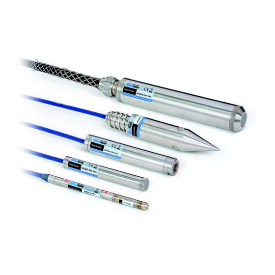
Model 4500
series
Vibrating Wire Piezometers
No part of this instruction manual may be reproduced, by any means, without the written consent of Geokon, Inc.
The information contained herein is believed to be accurate and reliable. However, Geokon, Inc. assumes no responsibility for
errors, omissions or misinterpretation. The information herein is subject to change without notification.
Copyright © 1983, 1996, 2002, 2004, 2005, 2007, 2008, 2009,2011, 2013 by Geokon, Inc.
(Doc Rev X 6/13)
Advertisement
Table of Contents

Related Manuals for Geokon 4500 Series


Summary of Contents for Geokon 4500 Series
- Page 1 Vibrating Wire Piezometers No part of this instruction manual may be reproduced, by any means, without the written consent of Geokon, Inc. The information contained herein is believed to be accurate and reliable. However, Geokon, Inc. assumes no responsibility for errors, omissions or misinterpretation.
- Page 3 The buyer's sole remedy for any breach of this agreement by Geokon, Inc. or any breach of any warranty by Geokon, Inc. shall not exceed the purchase price paid by the purchaser to Geokon, Inc. for the unit or units, or equipment directly affected by such breach.
-
Page 5: Table Of Contents
TABLE of CONTENTS 1. THEORY OF OPERATION ........................1 2. INSTALLATION ............................2 2.1 P ..........................2 RELIMINARY ESTS 2.1.1 Establishing an Initial Zero Reading ..................2 2.1.2 Checking the Calibration ......................3 2.2 I ................... 4 NSTALLATION IN TANDPIPES OR ELLS 2.3 I ...................... - Page 6 LIST of FIGURES, TABLES and EQUATIONS 1-1 V ....................1 IGURE IBRATING IEZOMETER 2-1 T ................4 IGURE YPICAL EVEL ONITORING NSTALLATIONS 2-2 T ..................5 IGURE YPICAL OREHOLE NSTALLATIONS ........6 ABLE SHOWING EMENT ENTONITE ATER RATIOS FOR TWO GROUT MIXES 2-3 T ....................
-
Page 7: Theory Of Operation
Geokon Model 4500 Vibrating Wire Piezometers are intended primarily for long-term measurements of fluid and/or pore pressures in standpipes, boreholes, embankments, pipelines and pressure vessels. Several models of the 4500 series are available (see Appendix A). Contact Geokon sales engineers for specific application information. -
Page 8: Installation
2. INSTALLATION (For Quick Installation Instructions see AppendixE) 2.1 Preliminary Tests Upon receipt of the piezometer the zero reading should be checked and noted (see Sections 3.1 to 3.3 for readout instructions). A thermistor is included inside the body of the piezometer (Figure 1-1) for the measurement of temperature (see Section 3.4 for instructions). -
Page 9: Checking The Calibration
the water column above the piezometer, calculate either the equivalent zero pressure reading, if the linear regression is used, or the factor, C, if the second order polynomial is used. A question may arise as to what to do with the filter stone while taking zero readings. If a standard stainless steel filter is being used, it will not matter if the filter stone is saturated or not. -
Page 10: Installation In Standpipes Or Wells
2.3 Installation in Boreholes Geokon piezometers can be installed in boreholes in either single or multiple installations per hole, in cased or uncased holes. See Figure 2-2. Careful attention must be paid to borehole sealing techniques if pore pressures in a particular zone are to be monitored. - Page 11 Fully Grouted Boreholes.Proceedings of FMGM 2003, Field Measurements in Geomechanics, Oslo, , is that it is not necessary to provide Norway, Sept. 2003. Contact Geokon for a copy o f this paper) sand zones and that the piezometer can be grouted directly into the borehole using a bentonite cement grout only.
-
Page 12: Installation In Fills And Embankments
(For more details on this method of installation ask for a copy of the FMGM paper) 2.4 Installation in Fills and Embankments Geokon piezometers are normally supplied with direct burial cable suitable for placement in fills such as highway embankments and dams, both in the core and in the surrounding materials. -
Page 13: Installation By Pushing Or Driving Into Soft Soils
In fills such as impervious dam cores where sub-atmospheric pore water pressure may need to be measured (as opposed to the pore air pressure) a ceramic tip with a high air entry value is often used which should be carefully placed in direct contact with the compacted fill material (see Installation A of Figure 2-3). -
Page 14: De-Airing Filter Tips
This section is detached from the rest of the drill string by rotating the string clockwise. The left hand thread will then loosen. The wings prevent the special EW rod from turning. A special LH/RH adapter is available from Geokon. The adapter is retrieved along with the drill string. -
Page 15: Removable Ceramic Filter, Model 4500S
2 Bar and Higher The proper procedure for de-airing and saturating these filters is somewhat complex and should be done either at the factory by Geokon or by carefully following the instructions below: Place the assembled piezometer, filter down, in a vacuum chamber with an inlet port at the bottom for de-aired water. -
Page 16: Model 4500Dp
Contact Geokon for splicing materials and additional cable splicing instructions. Junction boxes and terminal boxes are available from Geokon for all types of applications. In addition, portable readout equipment and datalogging hardware are available. See Figure 2-5. Contact Geokon for specific application information. -
Page 17: Lightning Protection
This will help shunt transients induced in the cable to ground thereby protecting the instrument. 2. Terminal boxes available from Geokon can be ordered with lightning protection built in. There are two levels of protection;... -
Page 18: Taking Readings
3. Improved protection using the LAB-3 can be had by placing the board in line with the cable as close as possible to the installed piezometer (see Figure 2-6). This is the recommended method of lightning protection. Piezometer Cable Ground Connection To Terminal Box/Readout Equipment Lightning Arrestor Board (LAB-3) Ground Stake... -
Page 19: Operation Of The Gk-404 Readout Box
3.2 Operation of the GK-404 Readout Box The GK404 is a palm sized readout box which displays the Vibrating wire value and the temperature in degrees centigrade. The GK-404 Vibrating Wire Readout arrives with a patch cord for connecting to the vibrating wire gages. -
Page 20: Measuring Temperatures
Equation B-1. For high temperature models use Table C1 or the equation C1 given on page 22. 4. DATA REDUCTION 4.1 Pressure Calculation The digits displayed by the Geokon Models GK-403, GK-404 or GK-405 Readout Boxes on channel B are based on the equation ... - Page 21 For example, a piezometer reading 8000 digits corresponds to a period of 354µs and a frequency of 2828 Hz. Note that in the above equation, the period is in seconds: the readout boxes display microseconds. Since digits are directly proportional to the applied pressure, Pressure = (Current Reading - Initial Reading) ×...
-
Page 22: Temperature Correction
Figure 4 – A Typical Calibration Sheet 4.2 Temperature Correction Careful selection of materials is made in constructing the vibrating wire piezometer to minimize thermal effects, however, most units still have a slight temperature coefficient. Consult the supplied calibration sheet to obtain the coefficient for a given piezometer. -
Page 23: Barometric Correction (Required Only On Un-Vented Transducers)
Since piezometers are normally installed in a tranquil and constant temperature environment, corrections are not normally required. If however, that is not the case for a selected installation, corrections can be made using the internal thermistor (Figure 1-1) for temperature measurement. See Section 3.4 for instructions regarding obtaining the piezometer temperature. -
Page 24: Vented Piezometers
When they have turned light pink in color they should be replaced. Contact Geokon for replacement capsules. 4.4 Environmental Factors Since the purpose of the piezometer installation is to monitor site conditions, factors which may affect these conditions should always be observed and recorded. -
Page 25: Troubleshooting
5. TROUBLESHOOTING Maintenance and troubleshooting of vibrating wire piezometers is confined to periodic checks of cable connections and maintenance of terminals. The transducers themselves are sealed and not user serviceable. Following are typical problems and suggested remedial action. • Piezometer fails to give a reading 1. -
Page 26: Appendix A - Specifications
133 mm 165 mm 187 mm 165 mm Table A-1 Vibrating Wire Piezometer Specifications Accuracy of Geokon test apparatus: 0.1% Contact Geokon for specific application information. Notes: 1 Accuracy of test apparatus: 0.05% 2 Other ranges available upon request. 3 0.1% FS linearity available upon request. -
Page 27: Appendix B - Standard Temperature Thermistor Temperature Derivation
APPENDIX B – STANDARD TEMPERATURE THERMISTOR TEMPERATURE DERIVATION Thermistor Type: YSI 44005, Dale #1C3001-B3, Alpha #13A3001-B3 Resistance to Temperature Equation B1: − 273 2 A B LnR C LnR T = Temperature in °C. Where; LnR = Natural Log of Thermistor Resistance A = 1.4051 ×... - Page 28 APPENDIX C – HIGH TEMPERATURE THERMISTOR TEMPERATURE DERIVATION Thermistor Type: Thermometrics BR55KA822J − Basic Equation, C1 273 2 A B LnR C LnR Where: T = Temperature in °C. LnR = Natural Log of Thermistor Resistance A = 1.02569 × 10 -3 B = 2.478265 ×...
-
Page 29: Appendix D - Notes Regarding The Model 4500C
APPENDIX D - NOTES REGARDING THE MODEL 4500C Installation The construction of this very slender vibrating wire transducer, requires a miniaturization of the internal parts and consequently they are somewhat delicate. Despite every precaution it is possible for the zero to shift during shipment due to rough handling. However, tests have shown that the zero may shift but the calibration factors do not change. -
Page 30: Appendix E - Non Linearity And The Use Of A Second Order Polynomial To Improve The Accuracy Of The Calculated Pressure
APPENDIX E - NON LINEARITY AND THE USE OF A SECOND ORDER POLYNOMIAL TO IMPROVE THE ACCURACY OF THE CALCULATED PRESSURE Most vibrating wire pressure transducers are sufficiently linear ( ± 0.2 % FS) that use of the linear calibration factor satisfies normal requirements. However, it should be noted that the accuracy of the calibration data, which is dictated by the accuracy of the calibration apparatus, is always ±... -
Page 31: Appendix F - Quick Instructions For Installing A Vibrating Wire Piezometer
APPENDIX F - QUICK INSTRUCTIONS FOR INSTALLING A VIBRATING WIRE PIEZOMETER. • Take a zero reading at zero, (atmospheric), pressure. Make sure that the temperature has not changed for 15 minutes previously. (Or until the piezo reading has stabilized). Check that this zero reading is compatible with the zero on the calibration sheet •... -
Page 32: Appendix G - Model 4500Ar Piezometer
APPENDIX G - Model 4500AR piezometer The Model 4500 AR piezometer is designed to be used with readouts systems that can read frequency but do not have the capability to “pluck’ the VW gage. This sensor has built-in electronics that cause the gage wire to vibrate in a continuous mode at its resonant frequency.
Need help?
Do you have a question about the 4500 Series and is the answer not in the manual?
Questions and answers