
Subscribe to Our Youtube Channel
Related Manuals for Geokon GK-404


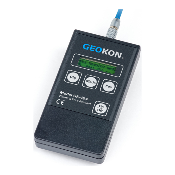
Summary of Contents for Geokon GK-404
- Page 1 Model GK-404 Vibrating Wire Readout Instruction Manual ©2019, GEOKON. All rights reserved. Document Revision: O | Release date: 11/15/19...
- Page 3 WARRANTY STATEMENT warrants its products to be free of defects in materials and workmanship, GEOKON under normal use and service for a period of 13 months from date of purchase. If the unit should malfunction, it must be returned to the factory for evaluation, freight prepaid.
-
Page 5: Table Of Contents
TABLE OF CONTENTS 1. INTRODUCTION ............................2. INITIAL SETUP ............................... 2.1 ACCESSORIES ............................2.2 CONNECTING A SENSOR ......................2.3 CONNECTING A LOAD CELL ...................... 3. OPERATION ............................... 3.1 POS (POSITION) BUTTON ......................3.2 MODE BUTTON ............................3.3 CONFIGURATION (CFG) BUTTON .................. - Page 6 FIGURES FIGURE 1: LEMO CONNECTOR ..................2 FIGURE 2: NECK STRAP CONNECTOR ................2 FIGURE 3: CONNECTOR ON GK-404 ................2 FIGURE 4: DOWNWARD-POINTING CONNECTOR ............3 FIGURE 5: NECK STRAP CONNECTIONS .................3...
- Page 7 TABLES TABLE 1: LOAD CELL WIRING DIAGRAM ............... 3 TABLE 2: POSITION SPECIFICATIONS................4 TABLE 3: VIBRATING WIRE READOUT ................9 TABLE 4: TEMPERATURE READOUT ................9 TABLE 5: PHYSICAL SPECIFICATIONS ................9 TABLE 6: TRANSDUCER PLUG PINOUT................9 TABLE 7: THERMISTOR RESISTANCE FOR 3KΩ ............10 TABLE 8: THERMISTOR RESISTANCE FOR 8.2KΩ............
- Page 8 EQUATIONS EQUATION 1: THERMISTOR RESISTANCE FOR 3KΩ.............10 EQUATION 2: THERMISTOR RESISTANCE FOR 8.2KΩ..........11 EQUATION 3: THERMISTOR RESISTANCE FOR 10KΩ...........12...
-
Page 9: Introduction
20 hours continuously on two AA batteries. It is designed for the readout of all Geokon vibrating wire gauges and transducers, and is capable of displaying the reading in either digits, frequency (Hz), period (μs), or microstrain (με). -
Page 10: Initial Setup
FIGURE 1: Lemo Connector to GK-404 FIGURE 2: Neck Strap Connector Place the larger circular hole onto the plastic nub on the back of the GK-404, with the bottom of the connector to the right (see the figure below). FIGURE 3: Connector on GK-404 Slide the connector all the way to the right, so that the nub on the back of the GK-404 locks into the smaller hole of the connector. -
Page 11: Connecting A Sensor
Thermistor Green's Black Blue's Black Yellow's Black White's black and Green wires are switched on Geokon three gauge VW load cells prior to serial number 3313. TABLE 1: Load Cell Wiring Diagram MODEL GK-404 VIBRATING WIRE READOUT | INITIAL SETUP | 3... -
Page 12: Operation
OPERATION To turn on the GK-404 on, press the On/Off button on the front panel of the unit. The initial startup screen will be displayed. After approximately one second, the GK-404 will start taking readings and display them based on the settings of the Pos and Mode buttons. -
Page 13: Default Settings
This is a bar graph display of the power remaining in the two 1.5V AA cells, with F for FULL and E for EMPTY. The GK-404 is capable of continuous operation for greater than 20 hours on a fresh set of batteries. -
Page 14: Maintenance
4.2 BATTERY REPLACEMENT Alkaline batteries are the best choice for use in the GK-404. A set of two 1.5V AA batteries are installed in the GK-404 at the factory. To replace the batteries, use a #1 Phillips screwdriver to remove the battery compartment cover located at the back of the readout. -
Page 15: Troubleshooting
SYMPTOM: DISPLAY SHOWS WEIRD CHARACTERS □ Switch the GK-404 to the ON setting while pushing the Cfg and Pos buttons at the same time, to restore the unit to its factory default settings. MODEL GK-404 VIBRATING WIRE READOUT | TROUBLESHOOTING | 7... -
Page 16: Limits Of Liability
GEOKON or indirectly by the proper or improper use of the GK-404 Vibrating wire readout, beyond the purchase price of the readout. 8 | LIMITS OF LIABILITY | GEOKON... -
Page 17: Appendix A. Specifications
Pin # on 5‑pin LEMO Flying Leads Alligator Wire Color Description (HGG.OB.305.CLLP) Clip Boot Color VW Gauge+ Black Black VW Gauge- White White Thermistor+ Green Green Thermistor- Bare Blue DrainWire TABLE 6: Transducer Plug Pinout MODEL GK-404 VIBRATING WIRE READOUT | SPECIFICATIONS | 9... -
Page 18: Appendix B. Thermistor Temperature Derivation
58.3 21.89K 2872 582.6 162.0 56.8 20.70K 2750 562.8 157.6 55.6 19.58K 2633 543.7 153.2 18.52K 2523 525.4 149.0 17.53K 2417 507.8 145.0 16.60K 2317 490.9 141.1 TABLE 7: Thermistor Resistance for 3kΩ 10 | THERMISTOR TEMPERATURE DERIVATION | GEOKON... -
Page 19: Thermistor Resistance For 8.2Kω
32.677 255 3.487 42.387 254.44 0.56 0.19 524.96 6.263 245.705 110.00 0.00 0.00 30.496 260 3.418 39.917 259.34 0.66 0.23 461.91 6.135 230.952 115.00 0.00 0.00 TABLE 8: Thermistor Resistance for 8.2kΩ MODEL GK-404 VIBRATING WIRE READOUT | THERMISTOR TEMPERATURE DERIVATION | 11... -
Page 20: Thermistor Resistance For 10Kω
341.9 125 158.6 157 81.1 45.0 8,057 2,316 62 810.6 94 333.2 126 155.1 158 79.5 44.3 7,722 2,235 63 786.6 95 324.8 127 151.7 159 78.0 43.5 TABLE 9: Thermistor Resistance for 10KΩ 12 | THERMISTOR TEMPERATURE DERIVATION | GEOKON... - Page 24 GEOKON Phone: +1 (603) 448-1562 GEOKON 48 Spencer Street Email: info@geokon.com is an ISO 9001:2015 Lebanon, New Hampshire Website: www.geokon.com registered company 03766, USA...
Need help?
Do you have a question about the GK-404 and is the answer not in the manual?
Questions and answers
how to read frequency on gk404 readout
The Geokon GK-404 Vibrating Wire Readout is designed to display readings in different formats, including frequency (Hz). To read frequency on the GK-404:
1. Ensure the unit is powered on with properly installed batteries.
2. Connect the vibrating wire gauge to the readout using the alligator clip connections.
3. Verify the connections are secure and the gauge resistance is between 90 and 180 ohms using an ohmmeter if needed.
4. The readout will display the measurement in various formats, including frequency (Hz).
5. If the display shows dashes instead of a reading, check the connections and try another gauge to confirm functionality.
The GK-404 readout provides frequency measurements with a resolution of 0.1 Hz and an accuracy of ±0.025% of full scale (6000 Hz).
This answer is automatically generated
Can't find temperature mode on my Gk 404