Table of Contents
Advertisement
Instruction Manual
Model 4500 series
Vibrating Wire Piezometer
No part of this instruction manual may be reproduced, by any means, without the written consent of Geokon, Inc.
The information contained herein is believed to be accurate and reliable. However, Geokon, Inc. assumes no responsibility for
errors, omissions or misinterpretation. The information herein is subject to change without notification.
Copyright © 2003-2017 by Geokon, Inc.
(REV CC, 2/2/2017)
Advertisement
Table of Contents

Subscribe to Our Youtube Channel
Related Manuals for Geokon 4500S


Summary of Contents for Geokon 4500S
- Page 1 Vibrating Wire Piezometer No part of this instruction manual may be reproduced, by any means, without the written consent of Geokon, Inc. The information contained herein is believed to be accurate and reliable. However, Geokon, Inc. assumes no responsibility for errors, omissions or misinterpretation.
- Page 3 The buyer's sole remedy for any breach of this agreement by Geokon, Inc. or any breach of any warranty by Geokon, Inc. shall not exceed the purchase price paid by the purchaser to Geokon, Inc. for the unit or units, or equipment directly affected by such breach.
-
Page 4: Table Of Contents
3.1 S ....................... 2 ATURATING ILTER 3.1.1 Piezometers with low air entry (standard) filter housings ..........2 3.1.2 Model 4500S equipped with option High Air Entry Ceramic Filter ....... 3 3.1.3 Model 4500C ........................4 3.2 E ................5 STABLISHING AN... - Page 5 7. TROUBLESHOOTING ......................27 APPENDIX A. - SPECIFICATIONS ..................29 A.1 S ..................29 TANDARD IEZOMETER IRING APPENDIX B. - THERMISTOR TEMPERATURE DERIVATION ........30 APPENDIX C. HIGH TEMPERATURE THERMISTOR LINEARIZATION....31 APPENDIX D. IMPROVING THE ACCURACY OF THE CALCULATED PRESSURE 32 APPENDIX E.
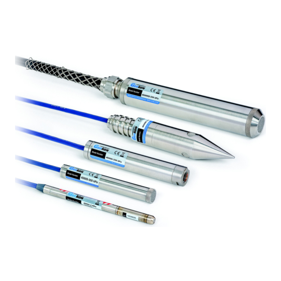
- Page 6 FIGURES 1 - M 4500S V .............. 1 IGURE ODEL IBRATING IEZOMETER 2 - 4500C S ....................... 4 IGURE ATURATION 3 - T ..............8 IGURE YPICAL EVEL ONITORING NSTALLATION 4 - T ................10 IGURE...
-
Page 7: Theory Of Operation
Portable readout units are available to provide the excitation, signal conditioning, and readout of the instrument. See Section 5 for instructions on using Geokon readouts with vibrating wire piezometers. Datalogger systems which allow remote, unattended data collection of multiple... -
Page 8: Quick Start Instructions
Caution! - Do not allow the piezometer to freeze once it has been filled with water! Most Geokon filter tips can be removed for saturation and then reassembled. To maintain saturation, the unit should be kept underwater until installation. (IMPORTANT: The filter stone and housing of model 4500C piezometers are not removable. -
Page 9: Model 4500S Equipped With Option High Air Entry Ceramic Filter
Two Bar and Higher: The proper procedure for de-airing and saturating these filters is somewhat complex, it is recommended that saturation be done at the factory by Geokon. If saturation must be done in the field, carefully follow the instructions below: 1) Place the assembled piezometer, filter down, in a vacuum chamber which has an inlet port at the bottom for de-aired water. -
Page 10: Model 4500C
3.1.3 Model 4500C The filter housing is not removable on the 4500C. Any attempt to remove the filter stone or the housing will destroy the transducer! If the pressure to be measured is less than 5 psi the filter stone must be saturated. A hand operated vacuum pump and short length of 1/2"... -
Page 11: Establishing An Initial Zero Reading
3.2 Establishing an Initial Zero Reading Vibrating Wire Piezometers differ from other types of pressure sensors in that they indicate a reading when no pressure is exerted on the sensor. It is imperative that an accurate initial zero reading be obtained for each piezometer, as this reading will be used for all subsequent data reduction. -
Page 12: Recommended Method
3.2.1 Recommended method: 1) Saturate the filter stone per Section 3.1 Caution: Do not allow the piezometer to freeze once it has been filled with water. 2) Replace the filter stone. 3) Hang the piezometer in the borehole at a point just above the water. 4) Wait until the piezometer reading has stopped changing. -
Page 13: Checking The Piezometer Performance
The smaller the borehole is, the greater the displacement will be. For example, a 4500S-50kPa piezometer lowered 50 feet below the water column in a one inch (.875 inch ID) -
Page 14: Installation
4. INSTALLATION 4.1 Installation in Standpipes or Wells 1) Saturate the filter stone and establish an initial zero reading by following the steps outlined in Section 3.1 and Section 3.2 2) Mark the cable where the top of the well or standpipe will reside once the piezometer has reached the desired depth. -
Page 15: Installation In Boreholes
4.2 Installation in Boreholes Geokon piezometers can be installed in cased or uncased boreholes, in either single or multiple piezometer configurations. If pore pressures in a particular zone are to be monitored, careful attention must be paid to the borehole sealing technique. Two methods of isolating the zone to be monitored are detailed below. -
Page 16: Figure 4 - Typical Borehole
Figure 4 - Typical Borehole Installations Installation C: It should be noted that since the vibrating wire piezometer is basically a no flow instrument, collection zones of appreciable size are not required. The piezometer can be placed directly in contact with most materials, provided that the fines are not able to migrate through the filter. The latest thinking is that it is not necessary to provide sand zones and that the piezometer can be grouted directly into the borehole using a bentonite cement grout only. -
Page 17: Table 1 - Cement /Bentonite
Pumping directly into the bottom of the borehole should be avoided. It is good practice to read the piezometer while pumping. For more details on grouting, refer to “Piezometers in Fully Grouted Boreholes” by Mikkelson and Green, FMGM proceedings Oslo 2003. Copies are available from Geokon. -
Page 18: Installation In Fills And Embankments
4.3 Installation in Fills and Embankments Geokon piezometers are normally supplied with direct burial cable suitable for placement in fills such as highway embankments and dams, both in the core and in the surrounding materials. For installations in non-cohesive fill materials, the piezometer may be placed directly in the fill, or, if large aggregate sizes are present, in a saturated sand pocket in the fill. -
Page 19: Figure 6 - Low Air Entry
In partially saturated fills (if only the pore air pressure is to be measured,) the standard tip is satisfactory. It should be noted that the standard coarse tip (low air entry) measures the air pressure when there is a difference between the pore air pressure and the pore water pressure. The difference between these two pressures is due to the capillary suction in the soil. -
Page 20: Installation By Pushing Or Driving Into Soft Soils
This section is detached from the rest of the drill string by rotating the string clockwise. The reaction wings prevent the EW rod from turning. A LH/RH adapter is available from Geokon. This adapter is retrieved along with the drill string. -
Page 21: Model 4500H And Model 4500Hh Transducer
4.5 Model 4500H and Model 4500HH Transducer Geokon Models 4500H and 4500HH are designed to be used in high temperature environments, up to 250 degrees Celsius. When connecting the Model 4500H transducer to external fittings, the fitting should be tightened into the 1/4-18NPT female port by placing a wrench on the flats provided on the transducer housing. -
Page 22: Splicing And Junction Boxes
Contact Geokon for splicing materials and additional cable splicing instructions. Junction boxes and terminal boxes are available from Geokon for all types of applications. In addition, portable readouts and dataloggers are also available. Contact Geokon for specific application information. -
Page 23: Lightning Protection
This is the recommended method of lightning protection. Terminal boxes available from Geokon can be ordered with lightning protection built in. The terminal board used to make the gage connections has provision for the installation of plasma surge arrestors. -
Page 24: Taking Readings
(bare). To turn the GK-404 on, press the “ON/OFF” button on the front panel of the unit. The initial startup screen will display: Geokon Inc. GK-404 verX.XX After approximately one second, the GK-404 will start taking readings and display them based on the settings of the POS and MODE buttons. -
Page 25: Gk-405 Readout Box
Connecting Sensors with Bare Leads: Attach the GK-403-2 flying leads to the bare leads of a Geokon vibrating wire sensor by connecting each of the clips on the leads to the matching colors of the sensor conductors, with blue representing the shield (bare). -
Page 26: Gk-403 Readout Box (Obsolete Model)
Connecting Sensors with Bare Leads: Attach the GK-403-2 flying leads to the bare leads of a Geokon vibrating wire sensor by connecting each of the clips on the leads to the matching colors of the sensor conductors, with blue representing the shield (bare). -
Page 27: Measuring Temperatures
5.4 Measuring Temperatures All vibrating wire piezometers are equipped with a thermistor which gives a varying resistance output as the temperature changes. The white and green leads of the instrument cable are normally connected to the internal thermistor. The GK-403, GK-404, and GK-405 readout boxes will read the thermistor and display the temperature in degrees C. -
Page 28: Data Reduction
Equation 1 - Digits Calculation For example, a piezometer reading 8000 digits corresponds to a period of 354s and a frequency of 2828 Hz. Note that in the above equation, the period is in seconds. Geokon readout boxes display microseconds. -
Page 29: Figure 12 - Typicalc
From "H 2 O 'H 2 O mm H 2 0 m H 2 0 "HG mm HG mbar .036127 .43275 .0014223 1.4223 .49116 .019337 14.696 .014503 14.5039 .14503 145.03 "H 2 O 27.730 .039372 39.372 13.596 .53525 406.78 .40147 401.47... -
Page 30: Temperature Correction
6.2 Temperature Correction The materials used in the construction of Geokon’s vibrating wire piezometers have been carefully selected to minimize thermal effects; however, most units still have a slight temperature coefficient. Consult the calibration sheet supplied with the instrument to obtain the coefficient for the individual piezometer. -
Page 31: Barometric Correction (Required Only On Unvented Transducers)
6.3 Barometric Correction (required only on unvented transducers) Since the standard piezometer is hermetically sealed, it responds to changes in atmospheric pressure. Corrections may be necessary, particularly for the sensitive, low pressure models. For example, a barometric pressure change from 29 to 31 inches of mercury would result in approximately one PSI of error (or 2.3 feet if monitoring water level in a well). -
Page 32: Vented Piezometers
SEAL SCREW MUST BE REMOVED BEFORE THE PIEZOMETER IS PUT INTO SERVICE! The desiccant capsules are blue when fresh. They will gradually turn pink as they absorb moisture. When they have turned light pink in color they should be replaced. Contact Geokon for replacement capsules. 6.5 Environmental Factors Since the purpose of the piezometer installation is to monitor site conditions, factors which may affect these conditions should always be observed and recorded. -
Page 33: Troubleshooting
Gages should not be opened in the field. Should difficulties arise, consult the following list of problems and possible solutions. For additional troubleshooting and support contact Geokon. Symptom: Piezometer fails to give a reading Check the resistance of the cable by connecting an ohmmeter to the sensor leads. Table 3 shows the expected resistance for the various wire combinations. - Page 34 Check the readout with another gage. The Piezometer may have been overranged or shocked. Inspect the diaphragm and housing for damage. Symptom: Piezometer reading unstable Connect the shield drain wire to the readout using the blue clip. (Green for the GK-401.) ...
-
Page 35: Appendix A. - Specifications
133 mm 165 mm 187 mm 165 mm Table 5 - Vibrating Wire Piezometer Specifications Accuracy of Geokon test apparatus: 0.1% Contact Geokon for specific application information. Notes: Accuracy of test apparatus: 0.05% Other ranges available upon request. 0.1% FS linearity available upon request. -
Page 36: Appendix B. - Thermistor Temperature Derivation
APPENDIX B. - THERMISTOR TEMPERATURE DERIVATION Thermistor Type: YSI 44005, Dale #1C3001-B3, Alpha #13A3001-B3 Resistance to Temperature Equation: -273.2 A+B LnR +C(LnR) Equation 6 - Resistance to Temperature Where; T Temperature in C. LnR Natural Log of Thermistor Resistance A ... -
Page 37: Appendix C. High Temperature Thermistor Linearization
APPENDIX C. HIGH TEMPERATURE THERMISTOR LINEARIZATION High Temperature Thermistor Linearization using SteinHart-Hart Log Equation Thermistor Type: Thermometrics BR55KA822J Resistance to Temperature Equation: -273.2 A+B LnR +C(LnR) Equation 7 - High Temperature Resistance to Temperature Where; T Temperature in C. LnR ... -
Page 38: Appendix D. Improving The Accuracy Of The Calculated Pressure
APPENDIX D. IMPROVING THE ACCURACY OF THE CALCULATED PRESSURE Most vibrating wire pressure transducers are sufficiently linear ( 0.2 % FS) so that the use of the linear calibration factor satisfies normal requirements. However, it should be noted that the accuracy of the calibration data, which is dictated by the accuracy of the calibration apparatus, is always ... -
Page 39: Appendix E. - Model 4500Ar Piezometer
APPENDIX E. - MODEL 4500AR PIEZOMETER Figure 13 - 4500AR The Model 4500 AR piezometer is designed to be used with readout systems that can read frequency but do not have the capability to “pluck” the VW gage. The sensor has built-in electronics that cause the gage wire to vibrate continuously at its resonant frequency.
Need help?
Do you have a question about the 4500S and is the answer not in the manual?
Questions and answers