Table of Contents
Advertisement
Quick Links
Download this manual
See also:
Instruction Manual
Instruction Manual
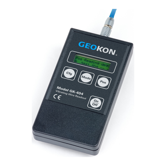
Model GK-404
Vibrating Wire Readout
No part of this instruction manual may be reproduced, by any means, without the written consent of Geokon, Inc.
The information contained herein is believed to be accurate and reliable. However, Geokon, Inc. assumes no responsibility for
errors, omissions, or misinterpretation. The information herein is subject to change without notification.
Copyright © 2003-2018 by Geokon, Inc.
(Doc Rev L, 1/25/18)
Advertisement
Table of Contents

Related Manuals for Geokon GK-404


Summary of Contents for Geokon GK-404
- Page 1 Vibrating Wire Readout No part of this instruction manual may be reproduced, by any means, without the written consent of Geokon, Inc. The information contained herein is believed to be accurate and reliable. However, Geokon, Inc. assumes no responsibility for errors, omissions, or misinterpretation.
- Page 3 Upon examination by Geokon, if the unit is found to be defective, it will be repaired or replaced at no charge. However, the WARRANTY is VOID if the unit shows evidence of having been tampered with...
-
Page 5: Table Of Contents
TABLE of CONTENTS 1. INTRODUCTION ..............................1 2. INITIAL SETUP ..............................1 2.1 A ............................... 1 CCESSORIES 2.2 C ............................2 ONNECTING A ENSOR 2.3 C ..........................2 ONNECTING A 3. OPERATION ................................4 3.1 POS (P ............................ 4 OSITION UTTON 3.2 M .............................. - Page 6 1 - L ........................1 IGURE ONNECTOR LIGNMENT 2 - N ........................... 1 IGURE TRAP ONNECTOR 3 - C GK-404 ..........................1 IGURE ONNECTOR ON 4 - C ......................2 IGURE ONNECTOR OINTING OWNWARD 5 - N ........................2 IGURE...
-
Page 7: Introduction
Before use, attach the flying leads to the GK-404 by aligning the red circle on the silver “Lemo” connector on the flying leads with the red line on the connector on the top of the GK-404. Insert the Lemo connector into the GK-404 until it locks into place (Figure 1). Remove the flying leads before storing the GK-404 in the carrying case. -
Page 8: Connecting A Sensor
Slide the connector all the way to the right, so that the nub on the back of the GK-404 locks into the smaller hole of the connector. Turn the connector clockwise until the part of the bottom of the connector is pointing down (Figure 4). -
Page 9: Table 1 - Load Cell Connector And Cable (Standard Wiring)
Blue Yellow Thermistor Green's Black Blue's Black Yellow's Black Table 1 - Load Cell Connector and Cable (Standard Wiring) Notes: ¹ White's black and Green wires are switched on Geokon three gage VW load cells prior to serial number 3313. -
Page 10: Operation
3. OPERATION To turn the GK-404 on, press the “ON/OFF” button on the front panel of the unit. The initial startup screen will be displayed. After approximately one second, the GK-404 will start taking readings and display them based on the settings of the POS and MODE buttons. -
Page 11: Mode Button
Press the MODE button to select automatic shutoff after five minutes, 15 minutes, or 30 minutes. The Auto-Off may be disabled so that the GK-404 will only shut off if the front panel ON/OFF button is pressed. The Auto-Off will only activate if no front panel buttons are pressed for the specified amount of time. -
Page 12: Low Battery Indication And Auto-Off
5. MAINTENANCE 5.1 Battery Replacement Alkaline batteries are the best choice for use in the GK-404. A set of two 1.5V AA batteries are installed in the GK-404 at the factory. To replace the batteries, use a #1 Phillips screwdriver to remove the battery compartment cover located at the back of the readout. -
Page 13: Troubleshooting
Readout. Note: Dashes will display if no Thermistor is connected. Symptom: Display shows weird characters Turn the GK-404 ON while pushing the CFG and POS buttons at the same time to restore the unit to its factory default settings. -
Page 14: Limits Of Liability
The GK-404 Vibrating Wire Readout has been developed specifically for use with Geokon, Inc. vibrating wire gages and, as such, Geokon, Inc. assumes no responsibility for its use with other systems. Every effort has been made to ensure reliable operation, but the user must be aware that there is no warranty against uninterrupted or trouble-free operation. -
Page 15: Appendix A. Specifications
APPENDIX A. SPECIFICATIONS A.1 Vibrating Wire Readout Excitation Range: 400 Hz to 6000 Hz, 5-volt square wave Measurement Resolution: 0.1 Hz, 0.1 uS, 0.1 Digit Measurement Accuracy: ±0.025% of Full Scale (6000 Hz) A.2 Temperature Readout Sensor Type: Thermistor, YSI 44005, Dale #1C3001-B3, Alpha #13A3001-B3 Sensor Accuracy: ±0.5°... -
Page 16: Appendix C. Thermistor Temperature Derivation
APPENDIX C. THERMISTOR TEMPERATURE DERIVATION Thermistor Type: YSI 44005, Dale #1C3001-B3, Alpha #13A3001-B3 Resistance to Temperature Equation: A+B ( LnR ) +C(LnR) -273.2 Equation 1 - Resistance to Temperature Where; T = Temperature in °C. LnR = Natural Log of Thermistor Resistance. A = 1.4051 ×...
Need help?
Do you have a question about the GK-404 and is the answer not in the manual?
Questions and answers