
Related Manuals for Geokon 4500 Series


Summary of Contents for Geokon 4500 Series
- Page 1 Model 4500 Series Vibrating Wire Piezometer Instruction Manual ©2021, GEOKON. All rights reserved. Document Revision: PP | Release date: 1/28/21...
- Page 3 WARRANTY STATEMENT warrants its products to be free of defects in materials and workmanship, GEOKON under normal use and service for a period of 13 months from date of purchase. If the unit should malfunction, it must be returned to the factory for evaluation, freight prepaid.
-
Page 5: Table Of Contents
TABLE OF CONTENTS 1. THEORY OF OPERATION ........................2. QUICK START INSTRUCTIONS ....................3. PRIOR TO INSTALLATION ....................... 3.1 SATURATING FILTER TIPS ......................3.1.1 SATURATING LOW AIR ENTRY (STANDARD) FILTERS ............ 3.1.2 SATURATING HIGH AIR ENTRY CERAMIC FILTERS ............3.1.3 SATURATING MODEL 4500C FILTER TIPS ................ - Page 6 6.2 TEMPERATURE CORRECTION ....................6.3 BAROMETRIC CORRECTION (REQUIRED ONLY ON UNVENTED TRANSDUCERS) ..........................6.4 MODEL 4500SV, VENTED PIEZOMETERS ..............6.5 ENVIRONMENTAL FACTORS ....................7. TROUBLESHOOTING ........................... APPENDIX A. SPECIFICATIONS ....................A.1 4500 SPECIFICATIONS ......................A.2 4500CR SPECIFICATIONS ....................... A.3 THERMISTOR ............................
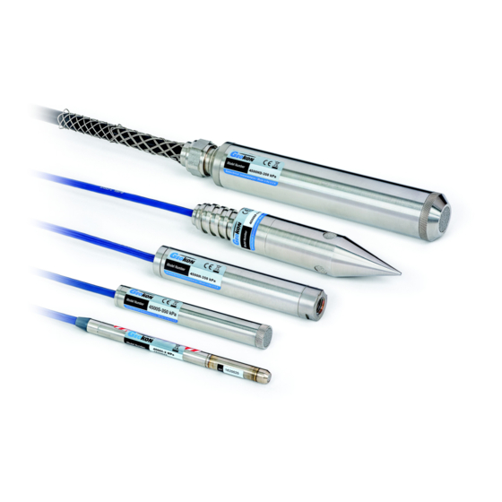
- Page 7 FIGURES FIGURE 1: MODEL 4500S VIBRATING WIRE PIEZOMETER ...........1 FIGURE 2: 4500C SATURATION ..................4 FIGURE 3: TYPICAL LEVEL MONITORING INSTALLATION ..........7 FIGURE 4: TYPICAL BOREHOLE INSTALLATIONS ............8 FIGURE 5: HIGH AIR ENTRY FILTER ................10 FIGURE 6: LOW AIR ENTRY FILTERS ONLY ..............10 FIGURE 7: TYPICAL SOFT SOILS INSTALLATION ............11 FIGURE 8: TYPICAL MULTI-PIEZOMETER INSTALLATION ...........12 FIGURE 9: RECOMMENDED LIGHTNING PROTECTION SCHEME ......13...
- Page 8 TABLES TABLE 1: CEMENT / BENTONITE / WATER RATIOS ............9 TABLE 2: ENGINEERING UNITS MULTIPLICATION FACTORS........17 TABLE 3: 4500 VIBRATING WIRE PIEZOMETER SPECIFICATIONS ......23 TABLE 4: 4500CR VIBRATING WIRE PIEZOMETER SPECIFICATIONS .......23 TABLE 5: STANDARD PIEZOMETER WIRING ..............23 TABLE 6: 3KΩ THERMISTOR RESISTANCE ..............24 TABLE 7: 10KΩ...
- Page 9 EQUATIONS EQUATION 1: DIGITS CALCULATION ................17 EQUATION 2: CONVERT DIGITS TO PRESSURE ............17 EQUATION 3: TEMPERATURE CORRECTION ..............18 EQUATION 4: BAROMETRIC CORRECTION..............18 EQUATION 5: CORRECTED PRESSURE CALCULATION ..........19 EQUATION 6: 3KΩ THERMISTOR RESISTANCE............. 24 EQUATION 7: 10KΩ THERMISTOR RESISTANCE............25 EQUATION 8: SECOND ORDER POLYNOMIAL EXPRESSION ........
-
Page 11: Theory Of Operation
For example, both models incorporate enhanced seals at the cable entry and filter connection; the 4500INCO uses a custom, dual O-ring seal, while the 4500TI is of an all-welded construction. MODEL 4500 SERIES VIBRATING WIRE PIEZOMETER | THEORY OF OPERATION | 1... -
Page 12: Quick Start Instructions
Warning! Do not allow the piezometer to freeze once the filter stone has been saturated! For installation in standpipes or wells, see Section 4.1. For boreholes, see Section 4.2. For fills and embankments, see Section 4.3. 2 | QUICK START INSTRUCTIONS | GEOKON... -
Page 13: Prior To Installation
. If saturation must be done in the field, carefully follow the instructions GEOKON below: MODEL 4500 SERIES VIBRATING WIRE PIEZOMETER | PRIOR TO INSTALLATION | 3... -
Page 14: Saturating Model 4500C Filter Tips
It will not matter if the filter stone is saturated when using a standard stainless steel filter. However, if the piezometer is equipped with a ceramic high air entry filter stone, then it must be saturated while taking the zero readings. 4 | PRIOR TO INSTALLATION | GEOKON... -
Page 15: Recommended Method For Establishing An Initial Zero Reading
Take a zero and temperature reading. (If this method is chosen, be sure that the piezometer is protected from sunlight or sudden changes of temperature. Wrapping it in some insulating material is recommended.) MODEL 4500 SERIES VIBRATING WIRE PIEZOMETER | PRIOR TO INSTALLATION | 5... -
Page 16: Alternative Method Three
The smaller the borehole is, the greater the displacement will be. For example, a Model 4500S-50KPA piezometer lowered 50 feet below the water column in a one-inch (0.875-inch ID) standpipe will displace the water level by more than four feet. 6 | PRIOR TO INSTALLATION | GEOKON... -
Page 17: Installation
Boreholes should be drilled without using drilling mud, or by using a material that degrades rapidly with time, such as Revert™. Wash the borehole clean of drill cuttings. Backfill the borehole with clean fine sand to a point six MODEL 4500 SERIES VIBRATING WIRE PIEZOMETER | INSTALLATION | 7... -
Page 18: Figure 4: Typical Borehole Installations
The general rule for installing piezometers in this way is to use a bentonite grout that mimics the strength of the surrounding soil. The emphasis should be on 8 | INSTALLATION | GEOKON... -
Page 19: Installation In Fills And Embankments
Bentonite plugs are placed at regular intervals to prevent migration of water along the cable path. In high traffic areas and in materials that exhibit pronounced "weaving", heavy-duty armored cable should be used. MODEL 4500 SERIES VIBRATING WIRE PIEZOMETER | INSTALLATION | 9... -
Page 20: Installation By Pushing Or Driving Into Soft Soils
4500DP only a few feet below the bottom of the hole. If the soil is too stiff, the sensor may overrange or break. 10 | INSTALLATION | GEOKON... -
Page 21: Model 4500H And Model 4500Hh Transducer
Because the vibrating wire output signal is a frequency rather than a current or voltage, variations in cable resistance have little effect on gauge readings. Therefore, splicing of cables has no effect, and in some cases may in fact be MODEL 4500 SERIES VIBRATING WIRE PIEZOMETER | INSTALLATION | 11... -
Page 22: Lightning Protection
Placing a Lightning Arrestor Board (LAB-3), in line with the cable, as close as possible to the installed piezometer (see Figure 9). These units utilize surge arrestors and transzorbs to further protect the piezometer. This is the recommended method of lightning protection. 12 | INSTALLATION | GEOKON... -
Page 23: Freezing Protection
If the piezometer is to be used in locations that are subject to freezing, can provide a GEOKON special modification that will protect the piezometer diaphragm. MODEL 4500 SERIES VIBRATING WIRE PIEZOMETER | INSTALLATION | 13... -
Page 24: Taking Readings
The GK-404 will continue to take measurements and display readings until the unit is turned off, either manually or by the Auto-Off timer (if enabled). For more information, consult the GK-404 manual. 14 | TAKING READINGS | GEOKON... -
Page 25: Gk-405 Vibrating Wire Readout
The white and green leads of the instrument cable are normally connected to the internal thermistor. The GK-404 and GK-405 readouts will read the thermistor and display the temperature in degrees Celsius. MODEL 4500 SERIES VIBRATING WIRE PIEZOMETER | TAKING READINGS | 15... - Page 26 48.5Ω per km (14.7Ω per 1000') at 20 °C. Multiply these factors by two to account for both directions. Look up the temperature for the measured resistance in Appendix B. 16 | TAKING READINGS | GEOKON...
-
Page 27: Data Reduction
6.2 TEMPERATURE CORRECTION The materials used in the construction of vibrating wire piezometers GEOKON have been carefully selected to minimize thermal effects; however, most units MODEL 4500 SERIES VIBRATING WIRE PIEZOMETER | DATA REDUCTION | 17... -
Page 28: Equation 3: Temperature Correction
In reality, conditions are not always ideal. For example, if the well is sealed, barometric effects at the piezometer level may be minimal or attenuated from the actual changes at the surface. Thus, errors may result from applying a 18 | DATA REDUCTION | GEOKON... -
Page 29: Figure 13: Vented Piezometers
THIS SEAL SCREW MUST BE REMOVED BEFORE THE PIEZOMETER IS PUT INTO SERVICE. MODEL 4500 SERIES VIBRATING WIRE PIEZOMETER | DATA REDUCTION | 19... - Page 30 Some of these factors include, but are not limited to, blasting, rainfall, tidal levels, traffic, temperature and barometric changes, weather conditions, changes in personnel, nearby construction activities, excavation and fill level sequences, seasonal changes, etc. 20 | DATA REDUCTION | GEOKON...
- Page 31 Refer to the expected resistance for the various wire combinations below. Vibrating Wire Sensor Lead Resistance Levels ≅180Ω Red/Black Green/White 3000Ω at 25 °C Any other wire combination will result in a measurement of infinite resistance. MODEL 4500 SERIES VIBRATING WIRE PIEZOMETER | TROUBLESHOOTING | 21...
- Page 32 22 | TROUBLESHOOTING | GEOKON...
-
Page 33: Table 3: 4500 Vibrating Wire Piezometer Specifications
A.4 STANDARD PIEZOMETER WIRING Function Wire Color Vibrating Wire Gauge + Vibrating Wire Gauge – Black Thermistor White Thermistor Green Cable Shield Shield Not Used TABLE 5: Standard Piezometer Wiring MODEL 4500 SERIES VIBRATING WIRE PIEZOMETER | SPECIFICATIONS | 23... -
Page 34: Table 6: 3Kω Thermistor Resistance
166.7 58.3 21.89K 2872 582.6 162.0 56.8 20.70K 2750 562.8 157.6 55.6 19.58K 2633 543.7 153.2 18.52K 2523 525.4 149.0 17.53K 2417 507.8 145.0 16.60K 2317 490.9 141.1 TABLE 6: 3KΩ Thermistor Resistance 24 | THERMISTOR TEMPERATURE DERIVATION | GEOKON... -
Page 35: Table 7: 10Kω Thermistor Resistance
45.0 8,057 2,316 62 810.6 94 333.2 126 155.1 158 79.5 44.3 7,722 2,235 63 786.6 95 324.8 127 151.7 159 78.0 43.5 TABLE 7: 10KΩ Thermistor Resistance MODEL 4500 SERIES VIBRATING WIRE PIEZOMETER | THERMISTOR TEMPERATURE DERIVATION | 25... -
Page 36: Equation 8: Second Order Polynomial Expression
C = 1595.7 It should be noted that where changes of water levels are being monitored it makes little difference whether the linear coefficient or the polynomial expression is used. 26 | IMPROVING THE ACCURACY OF THE CALCULATED PRESSURE | GEOKON... -
Page 37: Figure 14: Typical Calibration Report
APPENDIX D. TYPICAL CALIBRATION REPORT FIGURE 14: Typical Calibration Report MODEL 4500 SERIES VIBRATING WIRE PIEZOMETER | TYPICAL CALIBRATION REPORT | 27... -
Page 38: Figure 15: 4500Ar Piezometer
If the temperature reading is important, the power to the pressure sensor should be switched off while the thermistor reading is taken. 28 | MODEL 4500AR PIEZOMETER | GEOKON... - Page 39 MODEL 4500 SERIES VIBRATING WIRE PIEZOMETER | PIEZOMETER PRESSURE AND WATER LEVEL | 29...
Need help?
Do you have a question about the 4500 Series and is the answer not in the manual?
Questions and answers