Table of Contents
Advertisement
Quick Links
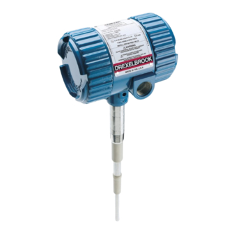
IntelliPoint RF
with Manual Calibration/Set Point
U.S. and Canada:
24-Hour Service:
International:
Fax:
E-mail:
drexelbrook.service@ametek.com
Website:
For Assistance Call 1-800-527-6297
Outside North America + 215-674-1234
Operating Instructions
Point Level Switch
1-800-553-9092
1-800-527-6297
+1 215-674-1234
+1 215-674-2731
www.drexelbrook.com
Level Measurement
Installation and
RML Series
TM
Leader in
Advertisement
Table of Contents

Subscribe to Our Youtube Channel
Related Manuals for Ametek IntelliPoint RF RML Series


Summary of Contents for Ametek IntelliPoint RF RML Series
- Page 1 For Assistance Call 1-800-527-6297 Outside North America + 215-674-1234 Installation and Operating Instructions IntelliPoint RF RML Series Point Level Switch with Manual Calibration/Set Point U.S. and Canada: 1-800-553-9092 24-Hour Service: 1-800-527-6297 International: +1 215-674-1234 Fax: +1 215-674-2731 E-mail: drexelbrook.service@ametek.com Website: www.drexelbrook.com...
- Page 2 AMETEK Drexelbrook makes no warranty of any kind with regard to the material contained in this manual, including, but not limited to, implied warranties or fitness for a particular purpose. Drexelbrook shall not be liable for errors contained herein or for incidental or consequential damages in connection with the performance or use of material.
- Page 3 IntelliPoint RF RML Series Point Level Switch with Manual Calibration/Set Point 205 Keith Valley Road, Horsham, PA 19044 U.S. and Canada: 1-800-553-9092 24-Hour Service: 1-800-527-6297 International: +1 215-674-1234 Fax: +1 215-674-2731 An ISO 9001 Certified Company E-mail: drexelbrook.info@ametek.com Website: www.drexelbrook.com...
- Page 5 Extend your warranty! ...from 12 months to 36 months by registering your purchase. Please go to www.drexelbrook.com. Click on "Contact Us" then"Warranty Registration" and fill out the form.
- Page 6 Contents...
-
Page 7: Table Of Contents
Contents Section 1: Introduction ......................1 System Description ....................1 Technology ......................1 Model Number ....................... 2 Dual Compartment Housing .................. 4 Section 2: Installation ......................5 Unpacking ......................5 Mounting and Installation Guidelines ..............5 Input Wiring ......................8 Output Wiring - Relay Version ................ - Page 8 Section 1...
-
Page 9: Introduction
Introduction Section 1: Introduction System Description The AMETEK Drexelbrook, IntelliPoint RML and RGL Series point level switches detect the presence or absence of material and provide a relay output for control functions. The RML and RGL IntelliPoint switches are calibrated through a simple potentiometer adjustment. -
Page 10: Model Number
IntelliPoint RF RML Series Introduction Model Number IntelliPoint RF Technology RF Admittance Measurement Type Manual Calibration Manual Calibration (High Sensitivity) Input Universal Power Supply 21-100 VDC, 85-250 VAC, 0-400 Hz Housing No Approvals, Dual Compartment NEMA 4X/IP66, M20 x 1.5 conduit entries No Approvals, Dual Compartment NEMA 4X/IP66 ¾"... - Page 11 13.8 bar @ 232°C (200 PSI @ 450°F) with high bulk density (1) High Integrity Seal for 700-0002-360 int/rem 34.5 bar @ 149°C (500 PSI @ 300°F) IntelliPoint RF RML Series Introduction Hazardous Materials Sanitary (3) lowpressure 700-0202-036 int/rem 3.4 bar @ 149°C (50 PSI @ 300°F)
-
Page 12: Dual Compartment Housing
IntelliPoint RF RML Series Introduction Dual Compartment Housing Figure 1-3 Dual Compartment Housing Detail SENSING INPUT/OUTPUT ELEMENT, CUSTOMER CIRCUIT CONNECTION BOARD SIDE SIDE Unlocked Locked Lid Locking Mechanism (CENELEC Systems) Conduit Entries (2) ¾-inch NPT (FM/CSA Systems) Input and Output Module M20 x 1.5 (CENELEC Systems) -
Page 13: Installation
IntelliPoint RF RML Series Installation Section 2: Installation Unpacking Carefully remove the contents of the shipping carton and check each item against the packing list before destroying any packing material. If there is any shortage or damage report it to the factory immediately. - Page 14 IntelliPoint RF RML Series Installation Mounting and Installation Guidelines (continued) WARNING: IntelliPoint RF equipment is rated explosion-proof. When installing in areas where explosion is a concern [rated “potentially hazardous” (EU) or “hazardous classified” (USA)] observe all national and local regulations as well as specifications in the certificate.
- Page 15 IntelliPoint RF RML Series Installation Mounting and Installation Guidelines (continued) Mount the sensing element as to avoid enhancing electrostatic discharge from the process medium, as is good practice with any thermowell, displacer, or sampler. This includes correct bonding to the tank or silo wall.
-
Page 16: Input Wiring
IntelliPoint RF RML Series Installation Input Wiring WARNING: If the IntelliPoint instrument is located in a hazardous environment, do not open the enclosure cover or make/break any electrical connections without first disconnecting electrical power at the source. Ensure the wiring, electrical fittings, and conduit connections conform to electrical codes for the specific location and hazard level. -
Page 17: Spark Protection
IntelliPoint RF RML Series Installation Spark Protection Applications involving insulating granulars and insulating liquids may produce a static discharge that can damage the electronics. The RF series instrument is supplied with integral heavy-duty spark protection to prevent static discharges from damaging the electronic units. - Page 18 IntelliPoint RF RML Series Installation 2.6.2 Time Delay Action Time delay action describes whether the relay contacts are delayed from going into the alarm state or recovering from an alarm state. • FWD: Delays system from coming out of alarm.
-
Page 19: Output And Led Status
IntelliPoint RF RML Series Installation 2.6.5 Function Check (Continued) circuit side of the housing. After pressing the button, the green LED flashes for 5 seconds and the two red LEDs light. The relay contacts are moved to the alarm condition for 2 seconds. -
Page 20: Sensing Element Connection
IntelliPoint RF RML Series Installation Sensing Element Connection Sensing element connects to the rear side of the circuit board and is factory-installed. The sensing element is sealed to the housing and cannot be removed without permanent damage. For IntelliPoint RF instruments that are mounted remotely... - Page 21 IntelliPoint RF RML Series Installation Sensing Element Connection (continued) For IntelliPoint RF instruments that are mounted remotely from the sensing element, the cable connections from the sensing element to the electronic unit are made to the terminals on the sensing element side of the housing.
- Page 22 Section 3...
-
Page 23: Calibration
IntelliPoint RF RML Series Calibration Section 3: Calibration WARNING: Before removing the explosion-proof housing cover in a potentially hazardous area, make certain that the area is safe. When calibration is complete, the cover must be replaced. Each conduit from the explosion-proof case must be equipped with an approved seal fitting. - Page 24 IntelliPoint RF RML Series Calibration 3.3.1 Quick Calibration Quick Calibration method is ONLY recommended for horizontally mounted, bare metal, Cote-Shield sensing elements. In all cases it is necessary to have material level below the probe (sensing element in air). Red LED OFF = relay energized = normal condition 1.
- Page 25 IntelliPoint RF RML Series Calibration 3.3.2 Calibration of Horizontal Insulated Sensing Elements or Horizontal Sensing Elements in Insulating Materials Red LED OFF = relay energized = normal condition A. Begin with sensing element totally uncovered. B. Starting with calibration adjustor in full counter clockwise (ccw) position, slowly turn clockwise (cw) until relay just operates.
- Page 26 IntelliPoint RF RML Series Calibration 3.3.4 Recalibration If amount of preloading was recorded at time of initial calibration, it is possible to replace instrument without experimentally determining proper amount of preload. A. For recalibration using procedure in Section 3.3.2, follow...
- Page 27 IntelliPoint RF RML Series Calibration 3.3.5 Calibration of Adjustable Differential Units (HLFS and LLFS) A. Put Fail-Safe switch in HLFS position. FULL CCW See Section 2.6.3. B. Turn Set Point adjustor to full counterclockwise (ccw) position. FULL CCW C. Turn Differential adjustor to full counterclockwise (ccw) position as well.
- Page 28 IntelliPoint RF RML Series Calibration 3.3.7 Low Level Fail Safe Blind Calibration of Control w/Flush Sensing Element (Alarm when chute is empty at sensor) A. Start with sensing element uncovered, (no material at sensing element), and tuning adjustor full counterclockwise (ccw). Red LED will be OFF.
-
Page 29: Spare Parts List
IntelliPoint RF RML Series Spare Parts List Section 4: Spare Parts List Spare Parts List O-ring ............250-1-75 Housing ¾-inch NPT Conduit Entry ..260-2-540 Housing M20 Conduit Entry ...... 260-2-542 Input/Output Module ........385-48-6 Circuit Board ..........Contact Factory Integral Sensing Element Cable ....380-9000-97... - Page 30 Section 5...
-
Page 31: Troubleshooting
IntelliPoint RF RML Series Troubleshooting Section 5: Troubleshooting WARNING: If IntelliPoint instrument is located in a hazardous environment, do not open enclosure cover or make/break any electrical connections without first disconnecting electrical power at the source. Ensure that wiring, electrical fittings, and conduit connections conform to electrical codes for the specific location and hazard level. -
Page 32: Testing Electronic Unit
IntelliPoint RF RML Series Troubleshooting Testing Electronic Unit Use the following steps to test the electronic unit: 1. Be sure environment is safe before removing lid from housing. 2. Observe failsafe jumper on circuit board on top of electronic unit (shown in Figure 2-5). Move jumper from current setting to alternate setting [HLFS to LLFS or vice versa]. -
Page 33: Over Range
IntelliPoint RF RML Series Troubleshooting Testing Relay Circuits (continued) Customer M4 / 2.5mm Hex Drive Connections View #8-32 / Phillips-Slotted Drive M3 / 2.5mm Hex Drive M3 / 2.5mm Hex Drive M5 / Slotted Drive Figure 5.2 Relay Circuit Operation... -
Page 34: Testing Remote Cable
IntelliPoint RF RML Series Troubleshooting Testing Remote Cable OHMMETER "0" CENTER - GROUND OHMS "0" CENTER - SHIELD OHMS "0" SHIELD - GROUND OHMS SHORTED WIRES SHOULD READ 0 OHMS SHORT OUT TWO CONDUCTORS CHECK FOR CONTINUITY OHMMETER CENTER - GROUND... -
Page 35: Factory Assistance
IntelliPoint RF RML Series Troubleshooting Factory Assistance AMETEK Drexelbrook can answer any questions about your level measurement system. Call Customer Service at 1-800- 553-9092 (US and Canada) , or +1-215-674-1234 If you require assistance and attempts to locate the problem have failed: •... -
Page 36: 5.12 Equipment Return
IntelliPoint RF RML Series Troubleshooting 5.12 Equipment Return In order to provide the best service, any equipment being returned for repair or credit must be pre-approved by the factory. In many applications, sensing elements are exposed to hazardous materials. • OSHA mandates that our employees be informed and protected from hazardous chemicals. -
Page 37: Specifications
IntelliPoint RF RML Series Specifications Section 6: Specifications RF/Capacitance Technology: None Calibration: Modes of High and Low level Operation: 2mm (0.08 inch) conductive liquids Repeatability Less than 1 second Response Time: 0 to 60 seconds forward and reverse acting. Time Delay: -30 to 70°C (-28 to 158°F) KEMA. - Page 38 Section 7...
-
Page 39: Control Drawings
IntelliPoint RF RML Series Control Drawings Section 7: Control Drawings FM Control Drawings... - Page 40 IntelliPoint RF RML Series Control Drawings FM Control Drawings (Continued)
- Page 41 IntelliPoint RF RML Series Control Drawings FM Control Drawings (Continued)
- Page 42 IntelliPoint RF RML Series Control Drawings FM Control Drawings (Continued)
- Page 43 IntelliPoint RF RML Series Control Drawings FM Control Drawings (Continued)
- Page 44 IntelliPoint RF RML Series Control Drawings FM Control Drawings (Continued)
- Page 45 IntelliPoint RF RML Series Control Drawings FM Control Drawings (Continued)
- Page 46 IntelliPoint RF RML Series Control Drawings FM Control Drawings (Continued)
- Page 47 IntelliPoint RF RML Series Control Drawings FM Control Drawings (Continued)
- Page 48 IntelliPoint RF RML Series Control Drawings FM Control Drawings (Continued)
- Page 49 IntelliPoint RF RML Series Control Drawings FM Control Drawings (Continued)
-
Page 50: Mounting And Wiring For Spark Protector Drawings
IntelliPoint RF RML Series Control Drawings Mounting and Wiring for Spark Protector Drawings... - Page 51 IntelliPoint RF RML Series Control Drawings Mounting and Wiring for Spark Protector (Continued)
- Page 52 IntelliPoint RF RML Series Control Drawings Mounting and Wiring for Spark Protector (Continued)
-
Page 53: Adding A Padded Capacitor
IntelliPoint RF RML Series Control Drawings Adding a Padded Capacitor... - Page 54 IntelliPoint RF RML Series Control Drawings Adding a Padded Capacitor (Continued)
- Page 55 IntelliPoint RF RML Series Control Drawings Adding a Padded Capacitor (Continued)
- Page 56 Appendix A...
-
Page 57: Appendix A Shortening Or Lengthening Sensing Element
Appendix A Shortening or Lengthening Sensing Element The Need Sometimes your application calls for probe lengths CAUTION: other than the standard 18-inch or longer insertion The insulation length of lengths supplied. Shortening the sensing element is either Flush Sensing quite simple and can be done in the field. Lengthening Elements or Insulated the sensing element, however, is more difficult because Sensing Elements can... - Page 58 Seller’s intellectual property rights or applicable other party is authorized to bind the AMETEK DREXELBROOK Division of AMETEK, Inc. law, or for any purposes other than that for which the items were furnished.
- Page 60 205 Keith Valley Road, Horsham, PA 19044 U.S. and Canada: 1-800-553-9092 24-Hour Service: 1-800-527-6297 International: +1 215-674-1234 Fax: +1 215-674-2731 An ISO 9001 Certified Company E-mail: drexelbrook.info@ametek.com Website: www.drexelbrook.com...
Need help?
Do you have a question about the IntelliPoint RF RML Series and is the answer not in the manual?
Questions and answers