Table of Contents
Advertisement
Quick Links
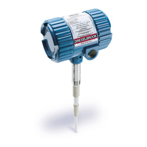
IntelliPoint RF
Telephone:
Fax:
E-mail:
drexelbrook.sales@ametek.com
Website:
Level Measurement
Operating Instructions
Point Level Switch
NOTICE:
+1 215-674-1234
+1 215-674-2731
www.drexelbrook.com
Installation and
RNL Series
TM
The AutoVerify™ feature in The
IntelliPoint™ switch is shipped DISABLED.
For critical High Level applications we
recommend enabling the AutoVerify™
feature.
Leader in
Advertisement
Table of Contents

Related Manuals for Ametek Drexelbrook IntelliPoint RF RNL Series


Summary of Contents for Ametek Drexelbrook IntelliPoint RF RNL Series
- Page 1 Operating Instructions IntelliPoint RF RNL Series Point Level Switch NOTICE: The AutoVerify™ feature in The IntelliPoint™ switch is shipped DISABLED. For critical High Level applications we recommend enabling the AutoVerify™ feature. Telephone: +1 215-674-1234 Fax: +1 215-674-2731 E-mail: drexelbrook.sales@ametek.com Website: www.drexelbrook.com...
- Page 2 AMETEK Drexelbrook makes no warranty of any kind with regard to the material contained in this manual, including, but not limited to, implied warranties or fitness for a particular purpose. Drexelbrook shall not be liable for errors contained herein or for incidental or consequential damages in connection with the performance or use of material.
- Page 3 RNLXX1-LM Issue# 25 IntelliPoint RF Series Point Level Switch 205 Keith Valley Road, Horsham, PA 19044 Telephone: +1 215-674-1234 Fax: +1 215-674-2731 E-mail: drexelbrook.sales@ametek.com Website: www.drexelbrook.com An ISO 9001 Certified Company...
- Page 4 Contents...
-
Page 5: Table Of Contents
Contents Section 1: Introduction System Description ..................1 Technology ....................1 Model Number .....................2 Sensing Element List ..................3 Dual Compartment Housing ...............4 Spare Parts List ...................5 Section 2: Installation Unpacking ....................7 Mounting and Installation Guidelines ............7 Input Wiring ....................9 Output Wiring - Relay Version ..............10 Spark Protection ..................10 Circuit Board ....................11 Output and LED Status ................14... - Page 6 Section 1...
-
Page 7: System Description
Introduction Section 1: Introduction System Description Installation of the AMETEK Drexelbrook IntelliPoint ™ Series Products is simple and easy. Simply apply power and IntelliPoint system is ready to detect the presence or absence of material. Since IntelliPoint instrument does not require calibration or setpoint adjustments, it is capable of operating in non-dedicated tanks regardless of the material being measured. -
Page 8: Model Number
RNLXX1 - IntelliPoint RF Series User's Manual Model Number IntelliPoint RF Technology RF Admittance Measurement Type 2pf Fixed Calibration Auto Calibration (2pf) Auto Calibration (10pf) Auto Calibration (0.5pf) 0.5pf Fixed Calibration 10pf Fixed Calibration Input Universal Power Supply 21-100 VDC, 85-250 VAC, 0-400 Hz Housing No Approvals, NEMA 4X/IP66, M20 X 1.5 conduit entries No Approvals, NEMA 4X/IP66, ¾”... -
Page 9: Sensing Element List
Introduction Sensing Element List Application Sensing Element Part Number Pressure/Temperature Wetted Parts General purpose 700‐1202‐001 Remote & 700‐1202‐021 Integral 13.8 bar @ 232°C (200 PSI @ 450°F) 316/316L SS and PEEK General purpose, longer insertion lengths w/cable attachment and 316/316L SS bottom weight 700‐1202‐014 Remote & 700‐1202‐024 Integral 13.8 bar @ 177°C (200 PSI @ 350°F) 316/316L SS and PEEK Proximity 700‐1202‐018 Remote & 700‐1202‐028 Integral 13.8 bar @ 232°C (200 PSI @ 450°F) 316/316L SS and PEEK with 76mm (3) 216SS proximity plate 700‐1202‐041 Remote 69 bar @ 121°C (1000 PSI @ 250°F) General purpose, high temperature and pressure 316/316L SS and PEEK 700‐1202‐042 Integral 20.7 bar @ 232°C (300 PSI @ 450°F) General purpose with FDA approved materials of construction 700‐1202‐031 Remote & 700‐1202‐032 Integral 13.8 bar @ 232°C (200 PSI @ 450°F) 316/316L SS and FDA grade PEEK General purpose for granular materials 700‐1202‐010 Remote & 700‐1202‐020 Integral 13.8 bar @ 232°C (200 PSI @ 450°F) 316/316L SS and PEEK with 7/8 inch dia. 316/316L SS collar 316/316L SS and FDA grade PEEK with 7/8 inch dia. 316/316L SS General purpose for granular materials w/FDA approved materials of construction 700‐1202‐033 Remote & 700‐1202‐034 Integral 13.8 bar @ 232°C (200 PSI @ 450°F) collar Corrosive liquids 700‐0001‐018 Remote ... -
Page 10: Dual Compartment Housing
RNLXX1 - IntelliPoint RF Series User's Manual Dual Compartment Housing Conduit Entries (2) Input/Output Module ¾-inch NPT (FM/FMc Systems) M20 x 1.5 (ATEX/IECEx Systems) LABEL (see below) 114 mm (4.5 inches) 140 mm (5.5 inches) External Lid Lock (2) M4 2.5 mm Hex Drive External Tag Loop (2) Equipotential Connection... -
Page 11: Spare Parts List
Introduction Spare Parts List O-ring ..................... 250-1-75 Housing ¾-Inch NPT Conduit Entry ..........260-2-540 Housing M20 Conduit Entry ............... 260-2-542 Input/ Output Module ................385-48-6 Input/ Output Module, Gold Relay ............. 385-48-18 Circuit Board RLL - 2pf Fixed Calibration ........... 385-48-003-FL2 RHL - Auto Calibration (0.5pf) ........ - Page 12 Section 2...
-
Page 13: Installation
Installation Section 2: Installation Unpacking Carefully remove the contents of the shipping carton and check each item against the packing list before destroying any packing material. If there is any shortage or damage, report it to the factory immediately. Mounting and Installation Guidelines CAUTION: The IntelliPoint RF instrument must NOT be powered BEFORE it is installed in an application and material... - Page 14 RNLXX1 - IntelliPoint RF Series User's Manual Mounting and Installation Guidelines (continued) After the system is installed and the level is below the sensing element, apply power. The RF series instrument wil automatically calibrate and is ready to detect change in level. If properly installed, the Green LED will illuminate when power is applied.
-
Page 15: Input Wiring
Installation Mounting and Installation Guidelines (continued) Best Cote-shield must extend through Wall build-up nozzle and wall does not extend build-up. past first insulator. Best No Nozzle Wrong Nozzle too long; NOZZLE Cote-shield too short. Good NOZZLE Long Nozzle Factory-supplied Cote-shield extends through nozzle and wall build-up. -
Page 16: Output Wiring - Relay Version
RNLXX1 - IntelliPoint RF Series User's Manual Input Wiring (Continued) M4 / 2.5mm Hex Drive #8-32 / Phillips-Slotted Drive One 5A SPDT Alarm and One 5A SPDT Fault M3 / 2.5mm Hex Drive M3 / 2.5mm Relay #1 Relay #2 Hex Drive 85 to 250 VAC M5 / Slotted Drive... -
Page 17: Circuit Board
Installation Circuit Board The circuit board is located on the sensing element/ circuit side of the housing (marked on label). Remove the housing lid to access the status LEDs, time delay adjustment, and configuration jumpers. See Figure 2-4. SENSING ELEMENT CIRCUITS VIEW ALARM POWER... - Page 18 RNLXX1 - IntelliPoint RF Series User's Manual 2.6.2 Time Delay Action TIME DELAY ACTION describes whether the relay contacts are delayed from going into the alarm state or recovering from an alarm state. • FWD: delays system from coming out of alarm. •...
- Page 19 Installation 2.6.5 Manual Certify The Manual Certify™ test feature performs a confidence test of the system by duplicating the same signal as a high-level alarm condition without requiring the system to be removed from the tank. • Simulating a high level with the Manual Certify feature: •...
-
Page 20: Output And Led Status
RNLXX1 - IntelliPoint RF Series User's Manual Output and LED Status There are three status LEDs located on the sensing element/ circuit board side of the housing. One is used to indicate that the unit has power. The remaining two LEDs are used to indicate the condition of RELAY #1 and RELAY #2. -
Page 21: Sensing Element Connection
Installation Sensing Element Connection Sensing element connects to the rear side of the circuit board and is factory-installed. The sensing element is sealed to the housing and cannot be removed without permanent damage. For IntelliPoint RF instruments that are mounted remotely from the sensing element, an additional housing with terminals is provided to connect the cable from the sensing element. - Page 22 RNLXX1 - IntelliPoint RF Series User's Manual Sensing Element Connection (continued) Housing and Bracket are G=Ground shown rotated S=Shield C=Center 90º for clarity. Figure 2-7 Sensing Element Connection (Remote Housing) SHIELD WIRE MUST BE CLIPP NOTE: CLIPPED SHIELD W MUST NOT TOU CONDULET HOUS...
-
Page 23: Section 3: Calibration Calibration
Manual Calibration IntelliPoint is recommended. If you purchased an "Auto-Calibration" IntelliPoint and have determined you require a "Manual Calibration" IntelliPoint based on the Application Guide, please contact the AMETEK Drexelbrook Service Department. 3.1.2 Using The IntelliPoint with Auto-Calibration After the IntelliPoint is installed in the vessel, simply apply power. -
Page 24: Re Calibration
RNLXX1 - IntelliPoint RF Series User's Manual Re Calibration CAUTION: The IntelliPoint RF instrument must be powered AFTER it is installed in application and with material BELOW sensing element. Do NOT push the Recal button without first ensuring that the material being measured is below the sensing element. -
Page 25: Intellipoint Calibration Mode Change
Calibration IntelliPoint Calibration Mode Change The IntelliPoint was shipped in a calibration mode that was determined to meet the needs of the application for which it was originally sold. If the IntelliPoint is used on a different application, or it is determined that a different calibration mode should be used, use the following procedure to make a calibration mode change. - Page 26 RNLXX1 - IntelliPoint RF Series User's Manual 3.3.1 Available IntelliPoint calibration modes (Continued) Calibration Mode changes Mode Selection change must be performed with the sensing element in air (Material below sensing element). 1. On the RF circuit board (Figure 3-1), temporarily remove the shunt jumper from the “Time Delay Selection Jumper”...
-
Page 27: Section 4: Troubleshooting
Troubleshooting Section 4: Troubleshooting RF Point Level Troubleshooting Guide Symptom Possible Cause Solution See Section Switch is in alarm and will Sensor is coated by a conductive material and the Need a sensor with a longer Cote-Shield Section 2.2, 4.5 not clear Cote-Shield™... -
Page 28: Testing Electronic Unit
RNLXX1 - IntelliPoint RF Series User's Manual WARNING: If the IntelliPoint instrument is located in a hazardous environment, do not open enclosure cover or make/break any electrical connections without first disconnecting electrical power at the source. Ensure that wiring, electrical fittings and conduit connections conform to electrical codes for the specific location and hazard level. -
Page 29: Over Range
Troubleshooting Over Range If the Red LED is flashing quickly (4 times/second), the IntelliPoint has detected that uncovered sensing element capacitance exceeds limits of transmitter. Consult factory for pad capacitor values and instructions. Under Range If the Red LED is flashing slowly (once per second), the IntelliPoint has detected that pad capacitor value is too large or a center wire to Cote Shieldshort. -
Page 30: Testing The Sensing Element
RNLXX1 - IntelliPoint RF Series User's Manual Testing The Sensing Element Integral electronics, See figure 2-6 Remove Sensing Element Circuit Board and disconnect cable from circuit board Remote electronics, See figure 2-7 Disconnect remote cable at the sensing element. 1. With the sensing element in the vessel, verify level is below the sensing element 2. - Page 31 Troubleshooting Testing The Sensing Element (Continued) c. If the sensing element still shows resistance between terminals of less than 10K ohms, it is possible that moisture is present internal to the sensing element. It may be possible to dry the sensing element until the resistance increases to a value in excess of 10K ohms.
- Page 32 RNLXX1 - IntelliPoint RF Series User's Manual Testing The Sensing Element (Continued) ANALOG ANALOG OHMMETER OHMMETER CENTER OUTER CONDUCTOR CONDUCTOR GROUNDED GROUNDED Red Lug HOUSING HOUSING PACKING PACKING GLAND GLAND DO NOT DISTURB DO NOT DISTURB PROBE MEASUREMENT SHIELD MEASUREMENT Figure 4-3 Checking the Sensing Element Center = Probe...
-
Page 33: Testing The Integral Cable
Troubleshooting Testing the Integral Cable 1. Disconnect integral cable from electronic. 2. Check for continuity. a. Using an ohmmeter measure the resistances. i. From the center wire connection on the RCA plug to the sensing element active section (center wire) ii. -
Page 34: Testing The Power Supply
RNLXX1 - IntelliPoint RF Series User's Manual Testing the Remote Cable (Continued) OHMMETER CENTER - GROUND OHMS CENTER - SHIELD OHMS SHIELD - GROUND OHMS CORRECT READING = OPEN CIRCUIT NO CONNECTION OHMMETER CHECK FOR SHORTS "0" CENTER - GROUND OHMS "0"... -
Page 35: Factory Assistance
Troubleshooting 4.10 Factory Assistance AMETEK Drexelbrook can answer any questions about your level measurement system. Call Customer Service at + 215-674-1234. If you require assistance and attempts to locate the problem have failed: • Contact your local Drexelbrook representative, •... -
Page 36: Equipment Return
Please include a purchase order even if the repair is under warranty. If repair is covered under warranty, you will not be charged. Ship equipment freight prepaid to: AMETEK-DREXELBROOK. 205 KEITH VALLEY ROAD HORSHAM, PA 19044-1499 COD shipments will not be accepted. - Page 37 Troubleshooting Section 5...
-
Page 38: Specifications
RNLXX1 - IntelliPoint RF Series User's Manual Section 5: Specifications Specifications RF/ Capacitance Technology: None Calibration: High and Low Level Modes of Operation: 2mm (0.08 inch) Conductive Liquids Repeatability: Less than 1 Second Response Time: 0 to 60 Seconds Forward & Reverse Acting Time Delay: -30 to 70°C (-22 to 158°F) ATEX Ambient Electronics:... -
Page 39: 5.2 Approvals Available
Specifications Section 5: Specifications (Continued) 5.2 Approvals Available: FM / FMc Explosionproof for Class I, Division 1, Groups A, B, C and D; Dust- Ignition proof for Class II, III, Division 1, Groups E, F and G; Non- incendive for Class I, Division 2, Groups A, B, C & D; Suitable for Class II, III, Division 2, Groups F &... -
Page 40: Section 6 : Control Drawings / Certificates
RNLXX1 - IntelliPoint RF Series User's Manual Section 6 : Control Drawings / Certificates FM / FMc Control Drawings... - Page 41 Control Drawings FM / FMc Control Drawings (Continued)
- Page 42 RNLXX1 - IntelliPoint RF Series User's Manual FM / FMc Control Drawings (Continued)
- Page 43 Control Drawings FM / FMc Control Drawings (Continued)
- Page 44 RNLXX1 - IntelliPoint RF Series User's Manual FM / FMc Control Drawings (Continued)
- Page 45 Control Drawings FM / FMc Control Drawings (Continued)
- Page 46 RNLXX1 - IntelliPoint RF Series User's Manual FM / FMc Control Drawings (Continued)
- Page 47 Control Drawings FM / FMc Control Drawings (Continued) COLUMNS 9 AND UP, DO NOT AFFECT SAFETY 1 2 3 4 - 5 6 7 8 - 9 10 11 12 L b - 0 c d e - * * * * a = MEASUREMENT OPTIONS: N = 2 pF AUTO-CAL M = MANUAL-CAL (STANDARD SENSITIVITY)
- Page 48 RNLXX1 - IntelliPoint RF Series User's Manual FM / FMc Control Drawings (Continued) COLUMNS 9 AND UP, DO NOT AFFECT SAFETY 1 2 3 4 - 5 6 7 8 - 9 10 11 12 L b - c d e f - * * * * a = MEASUREMENT OPTIONS: N = 2 pF AUTO-CAL...
- Page 49 Control Drawings FM / FMc Control Drawings (Continued) COLUMNS 9 AND UP, DO NOT AFFECT SAFETY 1 2 3 4 - 5 6 7 8 - 9 10 11 12 L b - c d e f - * * * * SENSING ELEMENTS: CONTINUED…...
- Page 50 RNLXX1 - IntelliPoint RF Series User's Manual FM / FMc Control Drawings (Continued) MODEL NUMBERS OF APPROVED SENSING ELEMENTS 700-mnop-qrs-t LEVEL PROBE m = FAMILY NUMBER: 0 THROUGH 9, BLANK m = FAMILY NUMBER: 0 THROUGH 9, BLANK o = 0 THROUGH 9, BLANK p = 0 THROUGH 9 q = FAMILY NUMBER: 0 THROUGH 9, BLANK r = FAMILY NUMBER: 0 THROUGH 9, BLANK...
- Page 51 Control Drawings FM / FMc Control Drawings (Continued) COLUMNS 11 AND UP, DO NOT AFFECT SAFETY 1 2 3 4 5 6 - 7 8 9 10 - 11 12 13 14 S a R b L c - 0 d e f - * * * * a = 2 SIL LEVEL 2 b = MEASUREMENT OPTIONS:...
- Page 52 RNLXX1 - IntelliPoint RF Series User's Manual FM / FMc Control Drawings (Continued) COLUMNS 11 AND UP, DO NOT AFFECT SAFETY 1 2 3 4 5 6 - 7 8 9 10 - 11 12 13 14 S a R b L c - d e g - * * * * a = 2 SIL LEVEL 2...
- Page 53 Control Drawings FM / FMc Control Drawings (Continued) SPECIFIC CONDITIONS OF USE “The equipment shall not be applied in an explosive dust atmosphere where high electrostatic charging processes are present that could result in propagating brush discharges. See IEC TS60079-32-1 for additional guidance.” Consult the manufacturer if dimensional information on the flameproof joints is necessary.
-
Page 54: Atex Control Drawings
RNLXX1 - IntelliPoint RF Series User's Manual ATEX Control Drawings... - Page 55 Control Drawings ATEX Drawings (Continued)
- Page 56 RNLXX1 - IntelliPoint RF Series User's Manual ATEX Drawings (Continued) COLUMNS 9 AND UP, DO NOT AFFECT SAFETY 1 2 3 4 - 5 6 7 8 - 9 10 11 12 L 2 - 0 b c d - * * * * a = MEASUREMENT OPTIONS: N = 2 pF AUTO-CAL M = MANUAL-CAL (STANDARD SENSITIVITY)
- Page 57 Control Drawings ATEX Drawings (Continued) COLUMNS 9 AND UP, DO NOT AFFECT SAFETY 1 2 3 4 - 5 6 7 8 - 9 10 11 12 L 2 - b c d e - * * * * a = MEASUREMENT OPTIONS: N = 2 pF AUTO-CAL M = MANUAL-CAL (STANDARD SENSITIVITY) H = 0.5 pF AUTO-CAL (HIGH SENSITIVITY)
- Page 58 RNLXX1 - IntelliPoint RF Series User's Manual ATEX Drawings (Continued) COLUMNS 9 AND UP, DO NOT AFFECT SAFETY 1 2 3 4 - 5 6 7 8 - 9 10 11 12 L 2 - b c d e - * * * * SENSING ELEMENTS: CONTINUED…...
- Page 59 Control Drawings ATEX Drawings (Continued) MODEL NUMBERS OF APPROVED INTRINSICALLY SAFE SENSING ELEMENTS 700-mnop-qrs-t LEVEL PROBE m = FAMILY NUMBER: 0 THROUGH 9, BLANK m = FAMILY NUMBER: 0 THROUGH 9, BLANK o = 0 THROUGH 9, BLANK p = 0 THROUGH 9 q = FAMILY NUMBER: 0 THROUGH 9, BLANK r = FAMILY NUMBER: 0 THROUGH 9, BLANK s = FAMILY NUMBER: 0 THROUGH 9...
- Page 60 RNLXX1 - IntelliPoint RF Series User's Manual ATEX Drawings (Continued) COLUMNS 11 AND UP, DO NOT AFFECT SAFETY 1 2 3 4 5 6 - 7 8 9 10 - 11 12 13 14 S a R b L 2 - 0 c d e - * * * * a = 2 SIL LEVEL 2 b = MEASUREMENT OPTIONS: N = 2 pF AUTO-CAL...
- Page 61 Control Drawings ATEX Drawings (Continued) COLUMNS 11 AND UP, DO NOT AFFECT SAFETY 1 2 3 4 5 6 - 7 8 9 10 - 11 12 13 14 S a R b L 2 - c d e f - * * * * a = 2 SIL LEVEL 2 b = MEASUREMENT OPTIONS: N = 2 pF AUTO-CAL...
- Page 62 RNLXX1 - IntelliPoint RF Series User's Manual ATEX Drawings (Continued) SPECIFIC CONDITIONS OF USE 1. The equipment shall not be applied in an explosive dust atmosphere where high electrostatic charging processes are present that could result in propagating brush discharges. See CLC/TR 60079-32-1 for additional guidance.
-
Page 63: Ce Declaration Of Conformity
Control Drawings CE Declaration of Conformity... -
Page 64: Iecex Control Drawings
RNLXX1 - IntelliPoint RF Series User's Manual IECEx Control Drawings... - Page 65 Control Drawings IECEx Control Drawings (Continued)
- Page 66 RNLXX1 - IntelliPoint RF Series User's Manual IECEx Control Drawings (Continued) COLUMNS 9 AND UP, DO NOT AFFECT SAFETY 1 2 3 4 - 5 6 7 8 - 9 10 11 12 R a L b - 0 c d e - * * * * a = MEASUREMENT OPTIONS: N = 2 pF AUTO-CAL M = MANUAL-CAL (STANDARD SENSITIVITY)
- Page 67 Control Drawings IECEx Control Drawings (Continued) COLUMNS 9 AND UP, DO NOT AFFECT SAFETY 1 2 3 4 - 5 6 7 8 - 9 10 11 12 R a L b - c d e f - * * * * a = MEASUREMENT OPTIONS: N = 2 pF AUTO-CAL M = MANUAL-CAL (STANDARD SENSITIVITY)
- Page 68 RNLXX1 - IntelliPoint RF Series User's Manual IECEx Control Drawings (Continued) COLUMNS 9 AND UP, DO NOT AFFECT SAFETY 1 2 3 4 - 5 6 7 8 - 9 10 11 12 R a L b - c d e f - * * * * SENSING ELEMENTS: CONTINUED…...
- Page 69 Control Drawings IECEx Control Drawings (Continued) MODEL NUMBERS OF APPROVED INTRINSICALLY SAFE SENSING ELEMENTS 700-mnop-qrs-t LEVEL PROBE m = FAMILY NUMBER: 0 THROUGH 9, BLANK m = FAMILY NUMBER: 0 THROUGH 9, BLANK o = 0 THROUGH 9, BLANK p = 0 THROUGH 9 q = FAMILY NUMBER: 0 THROUGH 9, BLANK r = FAMILY NUMBER: 0 THROUGH 9, BLANK s = FAMILY NUMBER: 0 THROUGH 9...
- Page 70 RNLXX1 - IntelliPoint RF Series User's Manual IECEx Control Drawings (Continued) COLUMNS 11 AND UP, DO NOT AFFECT SAFETY 1 2 3 4 5 6 - 7 8 9 10 - 11 12 13 14 S a R b L c - 0 d e f - * * * * a = 2 SIL LEVEL 2...
- Page 71 Control Drawings IECEx Control Drawings (Continued) COLUMNS 11 AND UP, DO NOT AFFECT SAFETY 1 2 3 4 5 6 - 7 8 9 10 - 11 12 13 14 S a R b L c - d e g - * * * * a = 2 SIL LEVEL 2 b = MEASUREMENT OPTIONS: N = 2 pF AUTO-CAL...
- Page 72 RNLXX1 - IntelliPoint RF Series User's Manual IECEx Control Drawings (Continued) SPECIFIC CONDITIONS OF USE: THE EQUIPMENT SHALL NOT BE APPLIED IN AN EXPLOSIVE DUST ATMOSPHERE WHERE HIGH ELECTROSTATIC CHARGING PROCESSES ARE PRESENT THAT COULD RESULT IN PROPAGATING BRUSH DISCHARGES. CONSULT THE MANUFACTURER IF DIMENSIONAL INFORMATION ON THE FLAMEPROOF JOINTS IS NECESSARY.
-
Page 73: Mounting And Wiring For Spark Protector Drawings
Control Drawings Mounting and Wiring for Spark Protector Drawings... - Page 74 RNLXX1 - IntelliPoint RF Series User's Manual Mounting and Wiring for Spark Protector (Continued)
- Page 75 Control Drawings Mounting and Wiring for Spark Protector (Continued)
-
Page 76: Adding A Padded Capacitor
RNLXX1 - IntelliPoint RF Series User's Manual Adding a Padded Capacitor... - Page 77 Control Drawings Adding a Padded Capacitor (Continued)
- Page 78 RNLXX1 - IntelliPoint RF Series User's Manual Adding a Padded Capacitor (Continued)
-
Page 79: Dual Seal Assembly For 700 Series Sensing Elements
Control Drawings Dual Seal Assembly for 700 Series Sensing Elements... - Page 80 RNLXX1 - IntelliPoint RF Series User's Manual Dual Seal Assembly (Continued)
- Page 81 Control Drawings Dual Seal Assembly (Continued)
- Page 82 Appendix: A...
-
Page 83: Shortening Or Lengthening The Sensing Element
Appendix A Appendix A: Shortening or Lengthening the Sensing Element CAUTION: The insulation length of either Flush Sensing Elements or Insulated Sensing Elements can NOT be changed. Cable Sensing Elements can only be shortened. Instructions are included with each unit. The Need Sometimes your application calls for probe lengths other than the standard 18-inch or longer insertion lengths... -
Page 84: Ce Installation Supplement
440-0018-731 Sht. APP'D BY RNLXX1 - IntelliPoint RF Series User's Manual DATE ISSUE EDO NO. APP'D 2-16-102 2-1-16 CE Installation Supplement 11-17-100 11-3-17 EMC Installation Supplement Purpose: To provide additional information that is required to be in compliance with the CE mark of conformity and 2014/30/EU Directive. Definitions: 1. -
Page 85: Ce Installation Supplement (Continued
Appendix A CE Installation Supplement (Continued) Sht. ISSUE 440-0018-731 3. Remote Installations Sensor port must be connected to the transmitter port by one of the following means: 401-16 Probe Filter • Coaxial cable run in conduit. • Triaxial cable. •... - Page 86 AMETEK, Inc. TERMS AND CONDITIONS OF SALE THE FOLLOWING TERMS/CONDITIONS, TOGETHER WITH ANY OTHER TERMS/CONDITIONS SPECIFICALLY AGREED TO IN WRITING BY SELLER, SHALL APPLY TO ALL ORDERS (“Order(s)”) FROM, AND SALES OF PRODUCTS (“Products”) OR SERVICES (“Services”) TO BUYER. ANY ACCEPTANCE OF ANY ORDER OF BUYER IS CONDITIONED UPON THESE TERMS/CONDITIONS. ANY ADDITIONAL OR DIFFERENT TERMS/CONDITIONS PROPOSED BY BUYER IN ANY DOCUMENT ARE OBJECTED TO AND SHALL NOT BE BINDING UPON SELLER.
- Page 87 WHETHER ORAL, WRITTEN, EXPRESS, IMPLIED OR STATUTORY. Seller’s prior written consent. Upon completion of Order, Buyer shall promptly return all Data to Seller together with all copies or reprints thereof NO IMPLIED OR STATUTORY WARRANTIES OF then in Buyer's possession or control, and Buyer shall thereafter make no MERCHANTABILITY OR FITNESS FOR PARTICULAR PURPOSE future use, either directly or indirectly, of any Data or any information SHALL APPLY.
- Page 89 205 Keith Valley Road, Horsham, PA 19044 An ISO 9001 Certified Company Telephone: +1 215-674-1234 Fax: +1 215-674-2731 E-mail: drexelbrook.sales@ametek.com RNLXX1-LM Issue 25 Website: www.drexelbrook.com EDO# 05-19-110...
Need help?
Do you have a question about the Drexelbrook IntelliPoint RF RNL Series and is the answer not in the manual?
Questions and answers