
Related Manuals for Ametek MAGNETROL 75 Series


Summary of Contents for Ametek MAGNETROL 75 Series
- Page 1 Model B73 & Series 75 Installation and Operating Manual Sealed External Cage Liquid Level Switches...
- Page 2 Certain conventions are used in this manual to ranty; then, AMETEK LMS will repair or replace the convey specific types of information. General control at no cost to the purchaser (or owner) technical material, support data, and safety infor- other than transportation.
-
Page 3: Table Of Contents
Model B73 & Series 75 Liquid Level Switches Table of Contents 1.0 Installation 5.0 Specifications 1.1 Unpacking ......4 5.1 Agency Approvals . -
Page 4: Installation
Installation Caution: If equipment is used in a manner not specified by manu- facturer, protection provided by equipment may be impaired. Unpacking Unpack the instrument carefully. Inspect all units for damage. Report any concealed damage to carrier with- in 24 hours. Check the contents of the packing slip and purchase order. -
Page 5: Mounting
Mounting Caution: This instrument is intended for use in Installation Category II, Pollution Degree 2. Adjust piping as required to bring control to a vertical position. Controls must be mounted within 3° of vertical in all directions. A three degree slant is noticeable by eye, but installation should be checked with a spirit level on top and/or sides of float chamber. - Page 6 3. Tighten set screw(s) at base of switch housing. 4. Unscrew and remove switch housing cover. The threads have been lubricated to facilitate removal. NOTE: For supply connections, use wire with a minimum rating of +167 °F (+75 °C) as required by process conditions. Use a minimum of 14 AWG wire for power and ground field wires.
-
Page 7: Reference Information
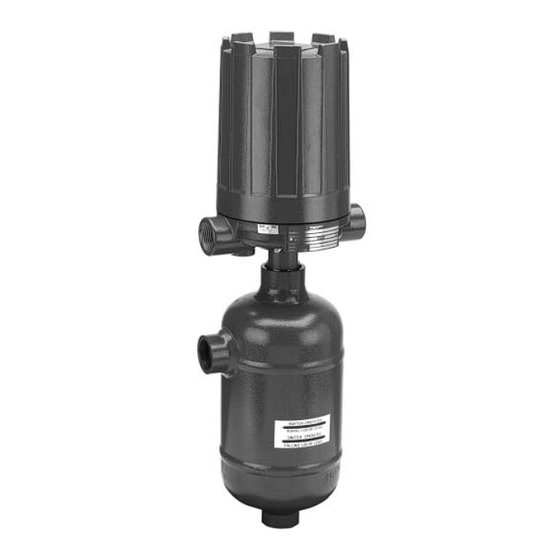
Reference Information Description B73 and Series 75 level switches are float operated units suitable for use on clean liquid applications for level alarm, pump control and safety shutdown func- tions. Series 75 units are available with tandem floats for applications where widely spaced high and low switching are required by a single control. -
Page 8: Switch Differential Adjustment
Switch Differential Adjustment The standard differential of Series 75 float models with one switch may be field adjusted. Adjustment may be necessary if a wider differential needs to be set to over- come switch chatter caused by the process. NOTE: This procedure may be applied to single switch models only. The differential, or the amount of level travel between switch-on and switch-off, may be adjusted by reposi- tioning the lower jam nuts on the float stem. - Page 9 5b. Close shut-off valves (if so equipped) to isolate control from tank. Drain off liquid in float chamber. 5c. On installations without shut-off valves, relieve pressure from the tank. Drain liquid in tank to a level below the connections of the float chamber. NOTE: Level control, connections and pipe lines need not be removed from the tank.
-
Page 10: High Level Controls
2.4.2 High Level Controls On high level controls, the switch trips on the higher actuation point and resets on the lower actuation point. Caution: On high level controls, widening the differential requires raising the trip point a proportional amount. The reset point will remain the same. -
Page 11: Differential Adjustment
2.5.2 Differential Adjustment Caution: No differential adjustment should be made on tandem float models in the field. Switch actuation levels have been set at the factory to meet customer specifications. Variations in actual conditions, from design conditions, usually require special control modifications. Troubleshooting Usually the first indication of improper operation is fail- ure of the controlled equipment to function, i.e., pump... -
Page 12: Check Sensing Unit
Check Sensing Unit 1. Reconnect power supply. Being careful to avoid electri- cal shock, manually actuate switch mechanism (use a non-conductive tool on electrical switch mechanisms) to determine whether controlled equipment will operate. Caution: With electrical power on, care should be taken to avoid contact with switch leads and connections at terminal block. - Page 13 12. Check float to be certain it is buoyant in the liquid (float chamber or vessel must have adequate liquid level). If float is determined to be filled with liquid, or it is col- lapsed, it must be replaced immediately. Do not attempt to repair a float.
-
Page 14: Preventive Maintenance
Preventive Maintenance Periodic inspections are a necessary means to keep your level control in good working order. This control is a safe- ty device to protect the valuable equipment it serves. A systematic program of preventive maintenance must be implemented when the control is placed into service. If the following is observed, your control will provide reliable protection of your capital equipment for many years. -
Page 15: Proof Test Procedure
4.1.3 Proof Test Procedure (To be performed annually at a minimum) 1. Bypass the logic controller or take other action to avoid a false trip. 2. Perform a detailed inspection of the unit inside and out for physical damage that may impact the structural integrity, and for evidence of environmental or process leaks. -
Page 16: What To Avoid
What To Avoid Caution: Operation of all buoyancy type level devices should be done in such a way as to minimize the action of dynamic forces on the float or displacer sensing element. Good practice for reducing the likelihood of damage to the control is to equalize pressure across the device very slowly. -
Page 17: Specifications
Specifications Agency Approvals EMC directive 2014/30/EU (electromagnetic compatibility) The following standard has been applied: EN 61326-1:2013-(Low Voltage Directive-CE) 46-620 B73 & Series 75 Liquid Level Switches... - Page 18 46-620 B73 & Series 75 Liquid Level Switches...
- Page 19 Maximum Pressure Ratings: These are the ranges of process pressure ranges based on each individual model as mentioned in each individual manual. Nominal Thickness Minimum Thickness Pressure Rating for (in) (in) 316 SST Version (psig) 0.035 0.0295 1300 0.065 0.0595 2710 0.093 0.087...
- Page 20 Switch Ratings RATING SWITCH SWITCH PROCESS LOAD VOLTS AC VOLTS DC SERIES TYPE TEMP RANGE Non-Inductive Amp 15.00 15.00 15.00 6.00 0.50 0.25 -40 to +250 °F Snap Inductive Amp 15.00 15.00 15.00 5.00 0.05 0.03 (-40 to +121 °C) Horseower —...
-
Page 21: Specific Conditions Of Use
Item Description/Ratings Installation and Erection TO PREVENT IGNITION OF HAZARDOUS ATMOSPHERES. DISCONNECT DEVICE FROM SUPPLY CIRCUIT BEFORE OPENING. KEEP ASSEMBLY TIGHTLY CLOSED WHEN IN OPERATION. Before attempting to remove a switch mechanism, be certain to pull disconnect switch or otherwise assure that electrical circuit through control is de-energized. -
Page 22: Physical
Physical STAINLESS STEEL CHAMBERS WITH 1-INCH CONNECTIONS INCHES MILLIMETERS NPT & ƒ Flanged Flanged Actuating NPT & Flanged Flanged Actuating ➀ ➁ ➁ Socket Weld Upper Side/Btm Side/Side Levels Socket Weld Upper Side/Btm Side/Side Levels Min. B73 0.59 6.36 2.83 17.44 9.25 6.25 20.32 9.90 6.25 21.00 1.22 2.10 151 235 159 515 251 159 C75 0.60 8.50 3.61 22.06 11.56 6.68 25.12 12.21 6.68 25.75 2.75 3.62 216... - Page 23 Inches (mm) « « « ∆ ∆ ∆ Series 75 Series 75 Series 75 ≈ Threaded and Socket Weld Flanged Upper Side/Bottom Flanged Side/Side Upper Side/Bottom 6.25 ≈ (158) 6.25 « ≈ (158) plugged « plugged 6.25 ≈ (158) ≈ ∆ «...
- Page 24 Physical CARBON STEEL CHAMBERS WITH 1-INCH CONNECTIONS INCHES MILLIMETERS NPT & ➂ Flanged Flanged Actuating NPT & Flanged Flanged Actuating ➀ Min. ➁ ➁ Socket Weld Upper Side/Btm Side/Side Levels Socket Weld Upper Side/Btm Side/Side Levels B73 0.59 6.36 3.34 17.44 9.25 6.25 20.32 9.90 6.25 21.00 1.22 2.10 151 84 442 235 159 515 251 159 532...
- Page 25 Inches (mm) ≈ ≈ ≈ ƒ ƒ ƒ Series 75 Series 75 Series 75 Series 75 ➂ Threaded and Socket Weld Flanged Upper Side/Bottom Flanged Side/Side Flanged Side/Side Upper Side/Bottom 6.25 ➃ (158) 6.25 ≈ ➃ (158) plugged ≈ plugged 6.25 ➃...
-
Page 26: Replacement Parts
Replacement Parts 6.1 Series 75 6.1.1 Parts Identification Item Description Housing cover Housing base Switch mechanism Jam nuts Lock washer Attraction sleeve Stop tube (not shown) Enclosing tube E-tube gasket Chamber assembly IMPORTANT: When ordering, please specify: A. Model and serial numbers or control. B. -
Page 27: Series 75 With Material Code 1
6.1.3 Series 75 with Material Code 1 All Models except S75, V75 & Z75 S75, V75 & Z75 Only Housing cover See Section 6.1.2, Switch and Housing Reference Housing base on previous page for switch and housing bulletin furnished. Switch mechanism Attraction sleeve kit: includes items 4, 5, 6 &... -
Page 28: Model B73
Model B73 6.2.1 Parts Identification Item Description Housing cover Housing base Switch mechanism Jam nuts Lock washer Attraction sleeve Enclosing tube E-tube gasket Chamber assembly IMPORTANT: When ordering, please specify: A. Model and serial numbers or control. B. Name and/or number of replacement assembly. Many Model 75 controls are specially tailored to meet customer specifications and, therefore, may contain special parts. -
Page 29: Series 75 Tandem Float Units
Series 75 Tandem Float Units 6.3.1 Parts Identification Item Description Housing cover Housing base Switch mechanism Jam nuts Upper attraction sleeve Lower attraction sleeve Spacer washer (not shown) Retaining ring E-tube gasket Enclosing tube Chamber assembly 6.3.2 Series 75 Tandem Float Units Models B, C, G, J, L, &... -
Page 30: Model Numbers
Model Numbers Model B73 MODEL NUMBER CODE Pressure Rating Model Min. psig @ °F bar @ °C ➀ Materials of Construction B73-1 0.59 Carbon steel chamber, 316 stainless steel float, 400 stainless steel trim B73-2 0.59 Carbon steel chamber, 316 stainless steel float, 316 stainless steel trim B73-4 0.59... - Page 31 ELECTRIC SWITCH MECHANISM AND ENCLOSURE Model B73-1 Only Models B73-2 & B73-4 Aluminum Enclosure FM (US/CA) FM (US/CA) ATEX / FM (US/CA) FM (US/CA) ATEX / Process Groups C&D Group B IECEx Groups C&D Group B IECEx Temperature One Set Point 1"...
-
Page 32: Series 75
Series 75 7.2.1 With Carbon Steel Chamber MODEL NUMBER CODE Pressure Rating Min. S.G. for models with ➁ Model Material of Construction Code Code psig @ °F bar @ °C ➀ ➂ 1000 ➂ ➂ ➂ 0.67 0.71 1000 0.55 0.59 0.55 0.56... - Page 33 ELECTRIC SWITCH MECHANISM AND ENCLOSURE All Models with All models with Material of Construction Code 1 Material of Construction Codes 2 Process ≈ except Models S75, V75 & Z75 and all Models S75, V75 & Z75 Temperature Switch Contacts Aluminum Enclosure Range Description Points...
-
Page 34: With Stainless Steel Chamber
Series 75 7.2.2 With Stainless Steel Chamber Pressure Rating Min. S.G. for models with ➁ Model Material of Construction Code Code psig @ °F bar @ °C ➀ 3 & 4 1000 ➂ ➂ ➂ ➂ 0.60 0.57 — — —... - Page 35 ELECTRIC SWITCH MECHANISM AND ENCLOSURE All models Process ƒ Aluminum Enclosure Temperature Switch Contacts Range Description Points FM (US/CA) FM (US/CA) ATEX / °F (°C) Groups C&D Group B IECEx 1" NPT 1" NPT 1" NPT SPDT Series B -40 to +250 Snap Switch (-40 to +121) DPDT...
- Page 36 Controls returned obtained from the factory, prior to the material's under our service policy must returned by return. This is available through the AMETEK LMS Prepaid transportation. AMETEK LMS will repair local representative or by contacting the factory.
Need help?
Do you have a question about the MAGNETROL 75 Series and is the answer not in the manual?
Questions and answers