
Related Manuals for Ametek Magnetrol3 Series


Summary of Contents for Ametek Magnetrol3 Series
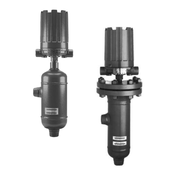
- Page 1 Series 3 Liquid Level Switches ASME B31.1 Construction Installation and Operating Manual...
- Page 2 In this manual, a warning indicates an imminently hazardous situation which, if not avoided, could result in serious injury or death. Copyright © 2021 AMETEK Magnetrol USA, LLC. Safety Messages All rights reserved. Follow all standard industry procedures for servicing elec-...
-
Page 3: Table Of Contents
Series 3 Liquid Level Switches ASME B31.1 Construction Table of Contents 1.0 Introduction 5.0 Reference Information 1.1 Principle of Operation ..........4 5.1 Agency Approvals............17 1.2 Operating Cycle ............4 5.2 Specifications ............18 5.2.1 Dimensional Data — Sealed Cage Models..18 2.0 Installation 5.2.2 Dimensional Specifications —... -
Page 4: Introduction
Introduction Enclosing tube The Magnetrol Series 3 level switches are float operated (non-magnetic) units suitable for use on clean liquid applications for level alarm, pump control and safety shutdown functions. Units Switch are designed, fabricated and certified to compliance with Return spring Magnet ASME B31.1 specifications. -
Page 5: Critical Alarm Function
Critical larm Function It is recommended that for critical alarm functions, an additional level switch be installed as a high–high or low– low level alarm for maximum protection. Conduit outlet Piping Pressure vessel Figure 3 shows a typical piping installation of a Magnetrol Series 3 control to a pressure vessel. -
Page 6: Wiring
Controls should be mounted as close to the vessel as possi- ble. This will result in a more responsive and accurate level change in the control. Liquid in a long line may be cooler and more dense than liquid in the vessel causing lower level indication in the control than actual level in the vessel. - Page 7 5. The switch terminals are located next to the conduit outlet to facilitate wiring. Bring supply wires through conduit outlet. Route extra wire around enclosing tube under the baffle plate and connect them to the proper terminals. Refer to the wiring diagram in your switch bulletin for this information.
-
Page 8: Switch Differential Adjustment
Switch Differential djustment The standard differential of Series 3 float models with only one switch mechanism may be field-adjusted. Adjustment may be necessary if a wider differential needs to be set to overcome switch chatter caused by the process. The differential, or the amount of level travel between “switch-on”... -
Page 9: High Level Controls
NOTE: Level control, connections and pipe lines need not be removed from the tank. 6. Loosen enclosing tube nut with a ⁄ " wrench. Unscrew Slight enclosing tube counterclockwise (switch and housing base play (gap) Must be Figure 6 will rotate also) until it is free. Refer to on page 8. -
Page 10: Preventive Maintenance
To widen the differential by raising the trip point, follow steps 1 through 16 in Low Level Controls, Section 3.1, pages 8–9). Caution: After increasing gap setting, be certain to check for proper operation of switch mechanism by raising and low- ering float assembly. -
Page 11: Proof Test Procedure
4. Vibration may sometimes cause terminal screws to loosen. Check all terminal connections to be certain that screws are tight. 5. On units with pneumatic switches, air (or gas) lines subjected to vibration, may eventually crack or loosen at connections causing leakage. Check lines and connections carefully and repair or replace, if necessary. -
Page 12: Control Head Removal And Installation
4.1.4 Control Head Removal and Installation Inspection of the interior of the chamber is possible on flanged cage models. To do this, the control head must be removed to provide proper access to the chamber. This procedure will assure that the head assembly is removed and reinstalled properly. - Page 13 8. Conduct a check for float stem straightness as follows: 8.1 Remove the stem assembly including attraction sleeve Top jam from the head assembly by removing the two screws Dim. A nuts Bottom jam holding the stop strap to the bottom of the flange. nuts Figure 10 for assembly schematic.
-
Page 14: Troubleshooting
Troubleshooting Usually the first indication of improper operation is failure of the controlled equipment to function, i.e., pump will not start (or stop), signal lamps fail to light, etc. When these symptoms occur, whether at time of installation or during routine service thereafter, check the following potential external causes first: •... -
Page 15: Check Sensing Unit
4.2.2 Check Sensing Unit 1. Reconnect power supply. Carefully actuate the switch mechanism manually (use a non-conductive tool on elec- trical switch mechanisms) to determine whether controlled equipment will operate. Shutoff valve (if used) Conduit Caution: With electrical power on, avoid contact with switch leads outlet and connections at terminal block. -
Page 16: What To Avoid
Caution: Do not attempt to repair a float. See Replacement Parts, Section 5.3 beginning on page 25. If all components in the control are in operating condition, the trouble is likely located external to the control. Repeat inspection of external conditions previously described. NOTE: If difficulties are encountered which cannot be identified, consult the factory or your local representative for assistance. -
Page 17: Reference Information
Reference Information gency pprovals AgENCy APPROvED MODEL APPROvAL CLASSES Class I, Div 1, Groups C & D All with an electric switch mechanism and a housing Class II, Div 1, Groups E, F & G listed as NEMA 4X/7/9 Class I, Div 1, Groups B, C & D All with an electric switch mechanism and a housing listed as NEMA 4X/7/9 Class I, Div 1, Group B Class II, Div 1, Groups E, F &... -
Page 18: Specifications
Specifications 5.2.1 Dimensional Data — Sealed Cage Models Inches (mm) NEMA 1: 8.50 (216) NEMA 4X/7/9: 10.12 (257) Group B: 10.12 (257) Plugged Plugged (Ref) (Ref) Figure 12 Threaded & Socket Weld Upper Side/Bottom Figure 13 Flanged Upper Side/Bottom Conduit Connections K Electrical Switches NEMA 4X/7/9: 1"... -
Page 19: Dimensional Specifications - Sealed Cage Models
5.2.2 Dimensional Specifications – Sealed Cage Models Inches (mm) CHAMBERS WITH 1-INCH CONNECTIONS — 150 LB. AND 300 LB. ANSI CLASS 1" NPT Threaded 1" Flanged 1" Flanged & Socket Weld Upper Side/Bottom Side/Side Model Code Std. 14" Std. 14" Std. - Page 20 5.2.2 Dimensional Specifications – Sealed Cage Models (cont.) Inches (mm) CHAMBERS WITH 1-INCH CONNECTIONS — 600 LB. & 900 LB. ANSI CLASS 1" NPT Threaded 1" Flanged 1" Flanged & Socket Weld Upper Side/Bottom Side/Side Model Code 14" 16" 14" 16"...
-
Page 21: Dimensional Data - Flanged Cage Models
5.2.3 Dimensional Data — Flanged Cage Models Inches (mm) NEMA 1: 8.50 (216) NEMA 4X/7/9: 10.12 (257) Group B: 10.12 (257) Plugged Plugged (Ref) (Ref) Figure 15 Threaded & Socket Weld Figure 16 Upper Side/Bottom Flanged Side/Side Conduit Connections K Electrical Switches NEMA 4X/7/9: 1"... -
Page 22: Dimensional Specifications - Flanged Cage Models
5.2.4 Dimensional Specifications – Flanged Cage Models 5.2.4.1 150# & 300# ANSI Pressure Ratings Inches (mm) CHAMBERS WITH 1-INCH CONNECTIONS 1" NPT Threaded 1" Flanged 1" Flanged & Socket Weld Upper Side/Bottom Side/Side Fig. Model Size Code (Lbs.) Std. 14" Std. -
Page 23: 600# & 900# Ansi Pressure Ratings
5.2.4.2 600# & 900# ANSI Pressure Ratings Inches (mm) CHAMBERS WITH 1-INCH CONNECTIONS 1" NPT Threaded 1" Flanged 1" Flanged & Socket Weld Upper Side/Bottom Side/Side Fig. Model Size Code (Lbs.) Std. 14" Std. 14" Std. 14" Std. 14" 9.12 3.63 18.39 14.00... -
Page 24: Actuating Levels, Steam Service Ratings And Specific Gravities
5.2.5 Actuating Levels*, Steam Service Ratings and Specific gravities For float operated units, minimum specific gravities and actuating levels vary depending upon the material of construction code used with the unit. NOTE: The minimum specific gravities and actuating levels shown are for single switch units with 1" process connections only. -
Page 25: Replacement Parts
Replacement Parts 5.3.1 Sealed Cage Float Models B35, C35, g35, v35 & Z35 Parts Identification Figure 18 Housing and Switch Mechanism Item Description Housing cover Housing base Switch mechanism Jam nuts (qty. 4) Washer Attraction sleeve Stop tube Enclosing tube ➀ E-tube gasket Chamber assembly Figure 19... -
Page 26: Flanged Cage Float Models B3F, G3F, K3F And Z3F Parts Identification
5.3.3 Flanged Cage Float Models B3F, g3F, K3F and Z3F Parts Identification Item Description Housing cover Housing base Switch mechanism Enclosing tube ➀ E-tube gasket Jam nuts (qty. 4) Washer (qty. 2) Attraction sleeve Stop tube Stop strap Screws (qty. 2) Float &... -
Page 27: Flanged Cage Float Models B3F, G3F, K3F And Z3F Part Numbers
5.3.4 Flanged Cage Float Models B3F, g3F, K3F and Z3F Part Numbers 150# Head Flange 300# Head Flange 600# Head Flange 900# Head Flange Material Code – P Material Code – P Material Code – P Material Code – P Housing kit Refer to bulletin on switch mechanism and housing base (includes items 1 and 2) -
Page 28: Model Numbers
Model Numbers 5.4.1 Sealed Cage Models MODEL NUMBER CODE Pressure Rating Model Minimum Code Specific psig @ °F bar @ °C ➀ gravity ➁ 0.69 1000 68.9 60.3 55.5 54.0 0.57 34.5 30.2 27.8 27.4 0.54 51.7 45.2 41.6 41.1 ¬... - Page 29 ELECTRIC SWITCH MECHANISM AND ENCLOSURE Models B35, C35 & g35 Models v35 & Z35 Process ➄ ➅ TyPE 4X/7/9 Aluminum Enclosure Temperature Switch Contacts Range Description ATEX ATEX Points Class I, Div 1 Class I, Div 1 Class I, Div 1 Class I, Div 1 Ex II 2 G EEx Ex II 2 G EEx...
-
Page 30: Flanged Cage Models
5.4.2 Flanged Cage Models MODEL NUMBER CODE Minimum Pressure Rating Model Head S.g. gravity ➁ Code Flange psig @ °F bar @ °C ➀ ANSI Class 150# 0.78 19.6 10.7 300# 0.66 51.0 39.6 34.8 28.3 600# 0.66 1000 68.9 60.3 55.5 54.8... - Page 31 ELECTRIC SWITCH MECHANISM AND ENCLOSURE All models except B3F, g3F, K3F & Z3F Models B3F, g3F, K3F & Z3F Process ➅ ∆ with 600# or 900# ANSI ratings with 600# or 900# ANSI ratings Temperature Switch TyPE 4X/7/9 Aluminum Enclosure Contacts Range Description...
- Page 32 No claims for misapplication, labor, direct or consequen- tial damage will be allowed. 705 Enterprise Street • Aurora, Illinois 60504-8149 USA 630.969.4000 • info.magnetrol@ametek.com • magnetrol.com BULLETIN: 46-624.10 EFFECTIvE: August 2021 Copyright © 2023 AMETEK Magnetrol USA, LLC SUPERSEDES: August 2017...
Need help?
Do you have a question about the Magnetrol3 Series and is the answer not in the manual?
Questions and answers