Advertisement
Quick Links
Advertisement

Related Manuals for Ametek MAGNETROL ASME B31.3 Construction


Summary of Contents for Ametek MAGNETROL ASME B31.3 Construction
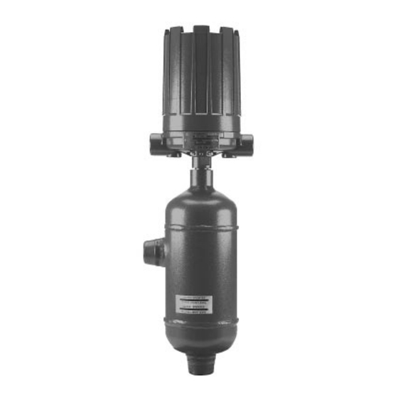
- Page 1 Series 3 Liquid Level Switches ASME B31.3 Construction Installation and Operating Manual...
- Page 2 Certain conventions are used in this manual to ranty; then, AMETEK LMS will repair or replace the convey specific types of information. General control at no cost to the purchaser (or owner) technical material, support data, and safety infor- other than transportation.
- Page 3 Series 3 Liquid Level Switches ASME B31.3 Construction Table of Contents 1.0 Introduction 5.3 Replacement Parts ........29 1.1 Principle of Operation ........4 5.3.1 Sealed Cage Float Models B35, C35, 1.2 Operating Cycle ..........4 G35, K35, L35, V35 and Z35 Parts Identification ......29 2.0 Installation 5.3.2 Sealed Cage Float Models B35, C35, 2.1 Unpacking............4...
- Page 4 Principle of Operation position The design of AMETEK LMS float operated level switches is based upon the principle that a magnetic field will penetrate non-magnetic materials such as 316 stainless steel. In this case, the float moves a magnetic attraction sleeve within a non-magnetic enclosing tube and actuates a switch mechanism.
- Page 5 Critical Alarm Function It is recommended that for critical alarm functions, an additional level switch be installed as a high–high or low–low level alarm for maximum protection. Conduit outlet Piping Pressure vessel shows a typical piping installation of an AME- Figure 3 TEK LMS Series 3 control to a pressure vessel.
- Page 6 Controls should be mounted as close to the vessel as possible. This will result in a more responsive and accu- rate level change in the control. Liquid in a long line may be cooler and more dense than liquid in the vessel caus- ing lower level indication in the control than actual level in the vessel.
- Page 7 5. The switch terminals are located next to the conduit outlet to facilitate wiring. Bring supply wires through conduit outlet. Route extra wire around enclosing tube under the baffle plate, and connect them to the proper terminals. Refer to the wiring diagram in your switch bulletin for this information.
- Page 8 Switch Differential Adjustment The standard differential of Series 3 float models with one switch mechanism may be field-adjusted. Adjustment may be necessary if a wider differential needs to be set to overcome switch chatter caused by the process. The differential, or the amount of level travel between “switch-on”...
- Page 9 NOTE: Level control, connections and pipe lines need not be removed from the tank. 6. Loosen enclosing tube nut with a ⁄ " wrench. Unscrew enclosing tube counterclockwise (switch and housing Slight play (gap) base will rotate also) until it is free. Refer to Figure 6 Must be Replace in same position...
- Page 10 To widen the differential by raising the trip point, follow steps 1 through 16 in Low Level Controls, Section 3.1, pages 8–9). Caution: After increasing gap setting, be certain to check for proper operation of switch mechanism by raising and low- ering float assembly.
- Page 11 NOTE: Check wiring carefully and replace at the first sign of brittle insulation. 4. Vibration may sometimes cause terminal screws to loosen. Check all terminal connections to be certain that screws are tight. 5. On units with pneumatic switches, air (or gas) lines subjected to vibration, may eventually crack or loosen at connections causing leakage.
- Page 12 4.1.4 Control Head Removal and Installation Inspection of the interior of the chamber is possible on flanged cage models. To do this, the control head must be removed to provide proper access to the chamber. This procedure will assure that the head assembly is removed and reinstalled properly.
- Page 13 8. Conduct a check for float stem straightness as follows: 8.1 Remove the stem assembly including attraction Top jam sleeve from the head assembly by removing the Dim. A nuts two screws holding the stop strap to the bottom of Bottom jam nuts the flange.
- Page 14 Troubleshooting Usually the first indication of improper operation is fail- ure of the controlled equipment to function, i.e., pump will not start (or stop), signal lamps fail to light, etc. When these symptoms occur, whether at time of instal- lation or during routine service thereafter, check the fol- lowing potential external causes first: •...
- Page 15 4.2.2 Check Sensing Unit 1. Reconnect power supply. Carefully actuate the switch mechanism manually (use a non-conductive tool on electrical switch mechanisms) to determine whether controlled equipment will operate. Shutoff valve (if used) Conduit Caution: With electrical power on, avoid contact with switch leads outlet and connections at terminal block.
- Page 16 Caution: Do not attempt to repair a float. See Replacement Parts, Section 5.3 beginning on page 29. If all components in the control are in operating condi- tion, the trouble is likely located external to the control. Repeat inspection of external conditions previously described.
- Page 17 Specifications Agency Approvals EMC directive 2014/30/EU (electromagnetic compatibility) The following standard has been applied: EN 61326-1:2013-(Low Voltage Directive-CE) 46-622 Series 3 Liquid Level Switches ASME B31.3 Construction...
- Page 18 46-622 Series 3 Liquid Level Switches ASME B31.3 Construction...
- Page 19 Maximum Pressure Ratings: These are the ranges of process pressure ranges based on each individual model as mentioned in each individual manual. Nominal Thickness Minimum Thickness Pressure Rating for (in) (in) 316 SST Version (psig) 0.035 0.0295 1300 0.065 0.0595 2710 0.093 0.087...
- Page 20 Switch Ratings RATING SWITCH SWITCH PROCESS LOAD VOLTS AC VOLTS DC SERIES TYPE TEMP RANGE Non-Inductive Amp 15.00 15.00 15.00 6.00 0.50 0.25 -40 to +250 °F Snap Inductive Amp 15.00 15.00 15.00 5.00 0.05 0.03 (-40 to +121 °C) Horseower —...
- Page 21 Item Description/Ratings Installation and Erection TO PREVENT IGNITION OF HAZARDOUS ATMOSPHERES. DISCONNECT DEVICE FROM SUPPLY CIRCUIT BEFORE OPENING. KEEP ASSEMBLY TIGHTLY CLOSED WHEN IN OPERATION. Before attempting to remove a switch mechanism, be certain to pull disconnect switch or otherwise assure that electrical circuit through control is de-energized.
- Page 22 Specifications 5.2.1 Dimensional Specifications — Sealed Cage Models NEMA 1: 8.50 (216) NEMA 4X/7/9: 10.12 (257) Group B: 10.12 (257) Plugged Plugged (Ref) (Ref) Figure 12 Threaded & Socket Weld Upper Side/Bottom Figure 13 Flanged Upper Side/Bottom Plugged Conduit Connections K Electrical Switches: 1"...
- Page 23 Specifications 5.2.1 Dimensional Specifications – Sealed Cage Models (cont.) Inches (mm) CHAMBERS WITH 1- INCH CONNECTIONS — 150 LB. AND 300 LB. ANSI CLASS 1" NPT Threaded & Socket Weld 1" Flanged Upper Side/Bottom 1" Flanged Side/Side Model Code Std. 14"...
- Page 24 Specifications 5.2.2 Dimensional Specifications — Flanged Cage Models NEMA 1: 8.50 (216) NEMA 4X/7/9: 10.12 (257) Plugged Group B: 10.12 (257) Plugged (Ref) (Ref) Figure 15 Threaded & Socket Weld Figure 16 Upper Side/Bottom Flanged Side/Side Plugged Conduit Connections K Electrical Switches: 1"...
- Page 25 Specifications 5.2.2 Dimensional Specifications – Flanged Cage Models (cont.) Inches (mm) CHAMBERS WITH 1-INCH CONNECTIONS 1" NPT Threaded 1" Flanged 1" Flanged Head & Socket Weld Upper Side/Bottom Side/Side Model Flg. Code Rating (lbs.) Std. 14" Std. 14" Std. 14" Std.
- Page 26 Specifications 5.2.2 Dimensional Specifications – Flanged Cage Models (cont.) Inches (mm) CHAMBERS WITH 2-INCH CONNECTIONS 2" NPT Threaded 2" Flanged 2" Flanged Head & Socket Weld Upper Side/Bottom Side/Side Model Flg. Code Rating (lbs.) Std. 14" Std. 14" Std. 14" Std.
- Page 27 Specifications 5.2.3 Actuating Levels* and Specific Gravities For float operated units, minimum specific gravities and actuating levels vary depending upon the material of construction code used with the unit. NOTE: The minimum specific gravities and actuating levels shown are for single switch units with 1" process connections only.
- Page 28 Specifications 5.2.3 Actuating Levels*, Steam Service Ratings and Specific Gravities (cont.) Inches (mm) DISPLACER MODELS WITH 1-INCH PROCESS CONNECTIONS Liquid Specific Gravity Process 0.40 0.50 0.60 0.70 0.80 0.90 1.00 Model Temp. °F Code (°C) 1.30 4.77 2.17 5.00 2.73 5.16 3.13 5.28...
- Page 29 Replacement Parts 5.3.1 Sealed Cage Float Models B35, C35, G35, K35, L35, V35 and Z35 Parts Identification Figure 18 Housing and Switch Mechanism Item Description Housing cover Housing base Switch mechanism Jam nuts (qty. 4) Washer Attraction sleeve Stop tube Enclosing tube ➀...
- Page 30 Replacement Parts 5.3.3 Sealed Cage Displacer Models B34 Parts Identification Item Description Housing cover Housing base Switch mechanism Jam nuts (qty. 5) Washer Attraction sleeve Stop tube Enclosing tube ➀ E-tube gasket Chamber assembly Figure 20 Sealed Cage Displacer Model B34 5.3.4 Sealed Cage Displacer Models B34 Part Numbers All models w/Material Code 1 All models w/Material Code 2...
- Page 31 Replacement Parts 5.3.5 Flanged Cage Displacer Model C34 Parts Identification Item Description Housing cover Housing base Switch mechanism Jam nuts (qty. 5) Enclosing tube ➀ E-tube gasket Attraction sleeve Washer (qty. 3) Screws (qty. 3) Spring & stem assembly Displacer assembly Retainer Washer Cotter pin (qty.
- Page 32 Replacement Parts 5.3.7 Flanged Cage Float Models B3F, G3F, K3F and Z3F w/Material Code 1 Parts Identification Item Description Housing cover Housing base Switch mechanism Enclosing tube ➀ E-tube gasket Jam nuts (qty. 4) Washer (qty. 2) Attraction sleeve Stop tube Stop strap Screws (qty.
- Page 33 Replacement Parts 5.3.9 Flanged Cage Float Models B3F, G3F, K3F and Z3F w/Material Codes 2 & N Parts Identification Item Description Housing cover Housing base Switch mechanism Enclosing tube ➀ E-tube gasket Jam nuts (qty. 4) Washer (qty. 2) Attraction sleeve Stop tube Stop strap Screws (qty.
- Page 34 Model Numbers 5.4.1 Sealed Cage Models MODEL NUMBER CODE Min. S.G. for Models Pressure Rating Model with Material of Code Construction Code ➁ psig @ °F bar @ °C ➀ 1000 FLOAT MODELS 0.69 0.72 1000 68.9 60.3 55.5 54.8 34.1 14.5 0.57...
- Page 35 5.4.1 Sealed Cage Models (cont.) ELECTRIC SWITCH MECHANISM AND ENCLOSURE Models B35, C35, K35 & L35 Models B34, V35, Z35 & all models with Material of Construction Code 1 with Material of Construction Code 2 Process ➇ Temperature Switch Aluminum Enclosure Contacts Range Description...
- Page 36 5.4.2 Flanged Cage Models ➁ Min. S.G. for Models Pressure Rating ➂ Head Model with Material of Flange Code psig @ °F bar @ °C Construction Code ANSI ➀ Class 2 or N 1000 FLOAT MODELS 150# 0.78 0.83 19.6 10.7 300# 0.66...
- Page 37 5.4.2 Flanged Cage Models (cont.) ELECTRIC SWITCH MECHANISM AND ENCLOSURE All models C34 and all models All models C34 and all models with with Material of Construction Code 1 Material of Construction Codes 2 & N except B3F, G3F, K3F & Z3F and B3F, G3F, K3F &...
- Page 38 NOTES: 46-622 Series 3 Liquid Level Switches ASME B31.3 Construction...
- Page 39 NOTES: 46-622 Series 3 Liquid Level Switches ASME B31.3 Construction...
- Page 40 Controls returned obtained from the factory, prior to the material's under our service policy must returned by return. This is available through the AMETEK LMS Prepaid transportation. AMETEK LMS will repair local representative or by contacting the factory.
Need help?
Do you have a question about the MAGNETROL ASME B31.3 Construction and is the answer not in the manual?
Questions and answers