Table of Contents
Advertisement
Quick Links
Advertisement
Table of Contents

Related Manuals for Ametek RFB 6000A


Summary of Contents for Ametek RFB 6000A
- Page 1 RF SWITCH NETWORK RFB 6000A USER MANUAL COMPLIANCE TEST SOLUTIONS...
- Page 2 RF SWITCH NETWORK RFB 6000A USER MANUAL This manual is based on firmware version 2:02.
-
Page 3: Table Of Contents
CONTENT Safety advice ........................5 1.1. General ..............................5 1.2. Connection to the mains and PE ......................5 1.3. Disconnection from the mains ......................... 5 1.4. Risk of electric shock ..........................5 1.5. Operating Environment ..........................5 1.6. Test execution ............................6 1.7. - Page 4 WRT:FLASH? ............................23 RFB 6000 Control Program ....................24 7.1. Basic functions ............................24 7.2. Description of the program ........................24 Technical specifications ..................... 26 Maintenance ........................29 9.1. General ..............................29 9.2. Cleaning ..............................29 Disposal ..........................29 RFB 6000A...
-
Page 5: Safety Advice
All the safety instructions and advice notes are to be observed. Neither AMETEK CTS Europe GmbH nor any of its subsidiary sales organizations can accept any responsibility for personal, material or consequential injury, loss or damage that results from improper use of the equipment and accessories. -
Page 6: Test Execution
Voltage Directive (LVD) 2014 / 35 / EU based on the following specifications applied: DIN EN 61326-1:2013 and DIN EN 61010-1:2011. It is the user’s responsibility to ensure that the test setup does not emit radiation which could disrupt „ other equipment. RFB 6000A... -
Page 7: Storage, Transport, Unpacking And Delivery Information
Keep the packaging. „ 2.4. Scope of delivery 2.4. Scope of delivery 2.4. Scope of delivery 2.4. Scope of delivery RFB 6000A mainframe „ RF switch plug-in module(s) and power meter interface as ordered separately „ Operating manual „ Spare fuses (2) „... -
Page 8: Description Of The Instrument
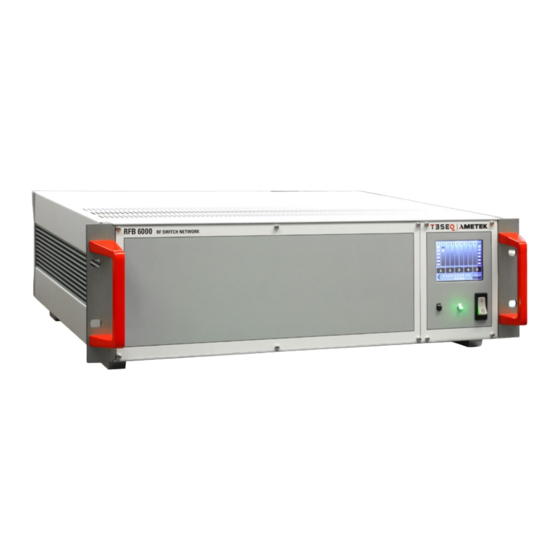
All RF switches are high quality with an operating lifetime of at least one million operations. While able to pass high power levels, they are designed to switch only during absence of RF power. Touch display Mains switch Status LED (Push to get the pin) Figure 1: Front panel Figure 2: View to the touch panel RFB 6000A... - Page 9 RS 485, LAN Remote control Power meter in- RF switch module and System via RS 232 optical terface (option) 1 to 2 N Control (option NRS 1200B) Power supply User port RF switch module RF switch module input and fuse 2x 1 to 6 SMA 1 to 6 N 100 - 240 V AC,...
-
Page 10: Touch Screen
Note: By touching the user port fields the correspond- ing bits High / Low are set. ON / OFF user port open collector outputs 1 to 4 Note: By touching the user port fields the correspond- ing bits High / Low are set. RFB 6000A... -
Page 11: Relay Control Screen
3.2.3. Relay control screen Shows current relay number (position) Blue color shows the selected path of the switch Set the switch position Touch to change the switch position Switches to the next relay Relay overview and range button screen User port control screen Switch to pervious relay or to Start screen 3.2.4. -
Page 12: User Port Setup Screen
Display of user port bits 1 to 10 Display of user port open collector bits 1 to 4 Switch to relay control screen The lower four fields indicate the state of the open collector outputs. In STORE mode, the current relay and user port settings are stored in the FLASH memory by pressing the RANGE keys. RFB 6000A... -
Page 13: Remote Interface
Touch here to toggle in the OFF state Example: Three relays (5, 7 and 8) are excluded from the switching with a Range Button By pressing the relay numbers, the respective relay can be brought into a passive state before programming a Range button. -
Page 14: User Port And Power Meter Interface
DIP switch SW 1: Sets the type of the RF switch Position 1 Position 2 Position 3 Position 4 Position 5 Position 6 Position 7 Position 8 Position 9 Position 10 Figure 5: DIP switch SW 2: Sets the position (number) of the RF switch RFB 6000A... -
Page 15: Operation
The RF Switch Network can be remote controlled via the optical RS232 interface. Included in the delivery of RFB 6000A is an USB-to-serial converter, USO 4013, which allows to connect the RF Switch Network with a PC with USB interface. -
Page 16: Applications
The requirement on the RF switch is, beside the switch functionality, to transmit all signals in best quality with low transmission error. The height of the transmission error is described by following frequency depending parameters: Insertion Loss „ Isolation „ VSWR „ 5.2. Example The RF switch network can be configured to switch RF signals in a wide range of automatic test systems. Various switch configurations are available, as needed for the emission or/and immunity test system. The following system drawings provide application examples. RFB 6000A... - Page 17 RF switch Signal generator 2x 1 to 6 Switch Power meter network (option SRS 1602B of PMR 600x Software RFB 6000 the RF switch network) dBµV Cable up to 10 m length Enter Power RFB 6000 RF SWITCH NETWORK Power Amp in Amp out Amp in...
- Page 18 Note: This example shows the recommended short RF connection between directional coupler and power meter for avoiding measuring errors. Figure 7: Example of a setup with 4 power amplifier, 3 directional couplers, 1 power meter and 2 antennas RFB 6000A...
-
Page 19: Software Commands
Command: REBOOT 6.3.2. IDN_PM? The RFB 6000A provides connectors for up to 8 external PM 600x power meter probes (optional). This command delivers the devices identification string of the connected power meter probes. The string is composed of the device name, its software version and its serial number. The command needs the power meter channel 1..8 as parameter. -
Page 20: Upd_Pm_Conf; Upd_Pm_Conf
This command expects the number of averages in the range of 1 to 10000 and a power meter channel number between 1..8. No reaction happens for unconnected power meters. Command: AVG? 25 2 Return: 0 RFB 6000A... -
Page 21: Blink; Blink
6.3.11. MONitor:DIGital? Reads all digital inputs on the rear panel of the RFB 6000A and returns a byte with a bit for each input set. For the structure of the returned byte please see table 5.1. For the pin assignment of the user port see table A.1 in appendix A on page 9. -
Page 22: Get:state
6.3.14. GET:STATE? Delivers the current switch position of a certain relay in the range of 0...6. All switches in the RFB 6000A are addressed by the letters A...J. They have to be used as the parameter for relay selection. A state of 0 indicates that the COM input is not connected with any output. -
Page 23: Set:statearr
Command: SET:USPOARR? 4 0,1,0,0,0,1,0,0,0,1,1,10,0 for range button 4 Return: 0 6.3.24. WRT:FLASH? Writes all settings which were made with SET:STAEARR? and SET:USPOARR? into the internal FLASH memory of the RFB 6000A. Command: WRT:FLASH? Return: 0 85-258150 E01... -
Page 24: Rfb 6000 Control Program
Description of the program After selecting the remote control interface and the corresponding COM port, a remote control connection to the RFB 6000A can be established using the Connect button. The type and switching position of the existing relay modules are automatically detected. - Page 25 The program mode is used to transfer the key assignments to the RFB 6000A so that the settings stored here can be easily transferred to the RFB 6000A and are then also available on the device itself without a remote control connection.
-
Page 26: Technical Specifications
5 - 40°C Humidity: < 80% (not condensation) Dimensions (W/H/D in mm): 483 x 150 x 423 Weight: approx. 10 kg Max. average power N type, SMA type Power Rating [watts] 10000 1000 1000 Frequency in GHz Frequency [GHz] RFB 6000A... - Page 27 Insertion loss N type, SMA type Insertion Loss Frequency in GHz Frequency [GHz] VSWR N type, SMA type VSWR maximum Frequency in GHz Frequency [GHz] 85-258150 E01...
- Page 28 User Port output 9 (LV logic, 1.5 / 3.5 V, ±16 mA) DO_8 User Port output 8 (LV logic, 1.5 / 3.5 V, ±16 mA) RS232 receive data (parallel to LWL) RS232 transmit data (parallel to LWL) Supply voltage (max. 0.7 A) +12V Supply voltage (max. 0.7 A) RFB 6000A...
-
Page 29: Maintenance
MAINTENANCE 9.1. General The RF Switch Network needs no special maintenance. The maintenance is limited to the cleaning of the contacts. The life time of the connectors and switches are limited because of the contact durability. Teseq can replace the worn out connectors and switches. No modifications are to be carried out on the RF Switch Network and accessories by the user. - Page 30 To fi nd your local partner within Teseq’s global network, please go to www.ametek-cts.com AMETEK CTS Europe GmbH is an ISO-registered company. Its products are designed and manufac- tured under the strict quality requirement of the ISO 9001. © July 2022 Teseq This document has been carefully checked.
Need help?
Do you have a question about the RFB 6000A and is the answer not in the manual?
Questions and answers