Table of Contents
Advertisement
Quick Links
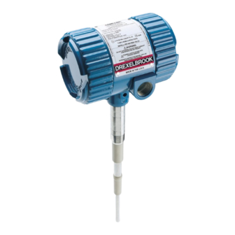
IntelliPoint RF
Two-Wire Point Level Switch
NOTICE:
Telephone:
Fax:
E-mail:
drexelbrook.sales@ametek.com
Website:
Level Measurement
Operating Instructions
The AutoVerify™ feature in The
IntelliPoint™ switch is shipped DISABLED.
For critical High Level applications we
recommend enabling the AutoVerify™
feature.
+1 215-674-1234
+1 215-674-2731
www.drexelbrook.com
Installation and
RNT Series
TM
Leader in
Advertisement
Table of Contents
Troubleshooting

Related Manuals for Ametek IntelliPoint RF RNT Series


Summary of Contents for Ametek IntelliPoint RF RNT Series
- Page 1 IntelliPoint RF RNT Series Two-Wire Point Level Switch NOTICE: The AutoVerify™ feature in The IntelliPoint™ switch is shipped DISABLED. For critical High Level applications we recommend enabling the AutoVerify™ feature. Telephone: +1 215-674-1234 Fax: +1 215-674-2731 E-mail: drexelbrook.sales@ametek.com Website: www.drexelbrook.com...
- Page 2 AMETEK Drexelbrook makes no warranty of any kind with regard to the material contained in this manual, including, but not limited to, implied warranties or fitness for a particular purpose. Drexelbrook shall not be liable for errors contained herein or for incidental or consequential damages in connection with the performance or use of material.
- Page 3 RNTXX1-LM Issue# 19 IntelliPoint RF Series Two-Wire Point Level Switch 205 Keith Valley Road, Horsham, PA 19044 Telephone: +1 215-674-1234 Fax: +1 215-674-2731 An ISO 9001 Certified Company E-mail: drexelbrook.info@ametek.com Website: www.drexelbrook.com...
- Page 4 Contents...
-
Page 5: Table Of Contents
Contents Section 1: Introduction System Description ..................1 Technology ....................1 Model Number .....................2 Sensing Element List ...................3 Dual Compartment Housing Detail ..............4 Section 2: Installation Unpacking ....................5 Mounting and Installation Guidelines ............5 Input Wiring ....................8 Spark Protection ..................8 Circuit Board ....................10 Output &... - Page 6 Section 1...
-
Page 7: Introduction System Description
Introduction Section 1: Introduction System Description Installation is simple and easy on the AMETEK Drexelbrook Series products. Simply apply power and the IntelliPoint ™ IntelliPoint system is ready to detect the presence or absence of material. Since the IntelliPoint instrument does not require calibration or setpoint adjustments, it is capable of operating in non-dedicated tanks regardless of the material being measured. -
Page 8: Model Number
RNTXX - IntelliPoint RF Series User's Manual Model Number IntelliPoint RF Technology RF Admittance Measurement Type Auto Calibration (2pf) Auto Calibration (10pf) Auto Calibration (0.5pf) 10pf Fixed Calibration 2pf Fixed Calibration 0.5pf Fixed Calibration Input Two wire Power Supply, 13-30 Vdc Housing No Approvals, NEMA 4X/IP66, M20 X 1.5 conduit entries No Approvals, NEMA 4X/IP66, ¾”... -
Page 9: Sensing Element List
Introduction Sensing Element List Application Sensing Element Part Number Pressure/Temperature Wetted Parts 700‐1202‐001 Remote General purpose 13.8 bar @ 232°C (200 PSI @ 450°F) 316/316L SS and PEEK 700‐1202‐021 Integral 700‐1202‐014 Remote General purpose, longer insertion lengths w/cable attachment and 316/316L SS bottom weight 13.8 bar @ 177°C (200 PSI @ 350°F) 316/316L SS and PEEK 700‐1202‐024 Integral 700‐1202‐018 Remote Proximity 13.8 bar @ 232°C (200 PSI @ 450°F) 316/316L SS and PEEK with 76mm (3) 216SS proximity plate 700‐1202‐028 Integral 700‐1202‐041 Remote 69 bar @ 121°C (1000 PSI @ 250°F) General purpose, high temperature and pressure 316/316L SS and PEEK 700‐1202‐042 Integral 20.7 bar @ 232°C (300 PSI @ 450°F) 700‐1202‐031 Remote General purpose with FDA approved materials of construction 13.8 bar @ 232°C (200 PSI @ 450°F) 316/316L SS and FDA grade PEEK 700‐1202‐032 Integral 700‐1202‐010 Remote General purpose for granular materials 13.8 bar @ 232°C (200 PSI @ 450°F) 316/316L SS and PEEK with 7/8 inch dia. 316/316L SS collar 700‐1202‐020 Integral 700‐1202‐033 Remote 316/316L SS and FDA grade PEEK with 7/8 inch dia. 316/316L SS ... -
Page 10: Dual Compartment Housing Detail
RNTXX - IntelliPoint RF Series User's Manual Dual Compartment Housing Detail Conduit Entries (2) Input/Output Module ¾-inch NPT (FM/FMc Systems) M20 x 1.5 (ATEX/IECEx Systems) LABEL (see below) 114 mm (4.5 inches) 140 mm (5.5 inches) External Lid Lock (2) M4 2.5 mm Hex Drive External Tag Loop (2) -
Page 11: Installation
Installation Section 2: Installation Unpacking Carefully remove the contents of the shipping carton and check each item against the packing list before destroying any packing material. If there is any shortage or damage, report it to the factory immediately. Mounting and Installation Guidelines CAUTION: The IntelliPoint RF instrument must be powered AFTER it is installed in the application and with material BELOW the... - Page 12 RNTXX - IntelliPoint RF Series User's Manual Mounting and Installation Guidelines (Continued) After system is installed and level is below the sensing element, apply power. The RF Series instrument automatically calibrates and is ready to detect change in level. If properly installed, the Green LED lights when power is applied.
- Page 13 Installation Mounting and Installation Guidelines (Continued) Mounting sensing element inside a pipe is not recommended. Do not mount a Cote-Shield sensing element through a nozzle that exceeds length of first insulator. Ensure that there are no obstructions or agitator blades to interfere with sensing element.
-
Page 14: Input Wiring
RNTXX - IntelliPoint RF Series User's Manual Input Wiring WARNING: If The IntelliPoint instrument is located in a hazardous environment, do not open the enclosure cover or make/break any electrical connections without first disconnecting electrical power at the source. Ensure that the wiring, electrical fittings and conduit connections conform to electrical codes for the specific location and hazard level. - Page 15 Installation Circuit Board The circuit board is located on the sensing element/circuit side of the housing (marked on label). Remove the housing lid to access the status LEDs, time delay adjustment, and configuration jumpers. See Figure 2-4. LEDs POWER GREEN ALARM OUTPUT CURRENT 8mA - ALARM...
-
Page 16: Circuit Board
RNTXX - IntelliPoint RF Series User's Manual 2.5.1 Time Delay The "Time Delay" adjustment is located on the sensing element/ circuit board side of the housing (marked on label). It is used to help stop an oscillating current output due to agitation or waves in the vessel. - Page 17 Certify feature operates when system is configured for HLFS. CAUTION: Unlike the previous AMETEK Drexelbrook Two Wire Point level Product (LCT), the IntelliPoint Two Wire Point Level Switch is designed with on board "AutoVerify" integrity testing. As such, it requires special instructions to be used with previous versions of AMETEK Drexelbrook receivers and cannot be used with some receiver versions.
- Page 18 RNTXX - IntelliPoint RF Series User's Manual 2.5.5 Manual / Remote Certify™ (Continued) Receiver Model Use with Description Comments Number IntelliPoint Single Channel Re- 401-04X0-001 Series ceiver To initiate Manual Certify, operator OK - Conditional: Single Channel Re- must press manual certify button on Activating Manual Verify 401-04X1-001 Series ceiver with Manual...
- Page 19 Installation 2.5.6 AutoVerify™ "AutoVerify" is a self-testing function that continuously checks the system for proper operation when the unit is in the High Level Failsafe (HLFS) mode and in normal condition. • AutoVerify is field-selectable using a jumper located on the sensing element side of the housing.
-
Page 20: Output & Status Leds
RNTXX - IntelliPoint RF Series User's Manual 2.5.7 Re-Calibration (Continued) LED Output Status The setpoint is stored in memory to indicate the last status of Tank Condition AutoVerify = disabled LED Output Status the switch. So, when the unit regains power the microprocessor Tank Condition AutoVerify = disabled reads the current value of the sensor and determines the status... -
Page 21: Sensing Element Connection
Installation Sensing Element Connection Sensing element connects to the rear side of the circuit board and is factory-installed. The sensing element is sealed to the housing and cannot be removed without permanent damage. For IntelliPoint RF instruments that are mounted remotely from the sensing element, an additional housing with terminals is provided to connect the cable from the sensing element. - Page 22 RNTXX - IntelliPoint RF Series User's Manual Sensing Element Connection (Continued) See Section 6.5 for Spark Protection, Mounting and Wiring 3 TERMINAL PROBE (TYP) Shield Wire Center Wire (RED) (BLUE) Housing and Bracket are G=Ground Ground Wire S=Shield shown rotated (GREEN) C=Center 90º...
-
Page 23: Calibration
Installation Calibration The Intellipoint™ model RNT (Standard Sensitivity) and RHT (High Sensitivity) feature Auto-Cal calibration. Auto- Calibration is suitable for liquid and slurry applications. For applications such as granular materials, interface measurement of two liquids, and plugged chute installations, a Manual Calibration IntelliPoint is recommended. - Page 24 RNTXX - IntelliPoint RF Series User's Manual 2.8.2 IntelliPoint Calibration Mode change The IntelliPoint was shipped in a calibration mode that was determined to meet the needs of the application for which it was originally sold. If, for some reason, the IntelliPoint is used on a different application, or for other reasons it is determined that a different calibration mode should be used, use the following procedure to make a calibration mode change.
- Page 25 Spare Parts List Calibration Mode changes Mode Selection change must be performed with the sensing element in air (Material below sensing element). 1. On the RF circuit board (Figure 2-8), temporarily remove the shunt jumper from the “Time Delay Selection Jumper” and place it on pins 1 &...
-
Page 26: Spare Parts List
RNTXX - IntelliPoint RF Series User's Manual Section 3: Spare Parts List O-ring ..................... 250-1-75 Housing ¾-Inch NPT Conduit Entry ..........260-2-540 Housing M20 Conduit Entry ............... 260-2-542 Input/ Output Module ................385-48-6 Input/ Output Module, Gold Relay ............. 385-48-18 Circuit Board RLT - 2pf Fixed Calibration ........... -
Page 27: Section 4: Troubleshooting
Section 4: Troubleshooting WARNING: If The IntelliPoint instrument is located in a hazardous environment, do not open enclosure cover or make/break any electrical connections without first disconnecting electrical power at the source. Ensure that wiring, electrical fittings and conduit connections conform to electrical codes for the specific location and hazard level. -
Page 28: Rf Point Level Troubleshooting Guide
RNTXX - IntelliPoint RF Series User's Manual RF Point Level Troubleshooting Guide Symptom Possible Cause Solution See Section Switch is in alarm and will Sensor is coated by a conductive material and the Need a sensor with a longer Cote-Shield Section 2.2, 4.5 not clear Cote-Shield™... -
Page 29: Testing Electronic Unit
Troubleshooting Testing Electronic Unit This test is only a test of the electronic unit for troubleshooting purposes, and does not serve as a Verify or Certify test of the complete system. Use the following steps to test the electronic unit: 1. -
Page 30: Over Range
RNTXX - IntelliPoint RF Series User's Manual Over Range If the Red LED is flashing quickly (4 times/second), IntelliPoint has detected that uncovered sensing element capacitance exceeds limits of transmitter. Consult factory for pad capacitor values and instructions. Under Range If the Red LED is flashing slowly (once per second), IntelliPoint has detected that pad capacitor value is too large or a center wire to Cote Shield short. - Page 31 Troubleshooting Testing The Sensing Element (Continued) the vessel. Verify the CoteShield element extends at least 2” into the vessel and past wall build-up. ii. Extremely conductive coating on the sensing element. This may require changing the sensing element or electronics. Contact the factory for recommendations. iii.
- Page 32 RNTXX - IntelliPoint RF Series User's Manual Testing The Sensing Element (Continued) ANALOG ANALOG OHMMETER OHMMETER CENTER OUTER CONDUCTOR CONDUCTOR GROUNDED GROUNDED Red Lug HOUSING HOUSING PACKING PACKING GLAND GLAND DO NOT DISTURB DO NOT DISTURB PROBE MEASUREMENT SHIELD MEASUREMENT Figure 4-2 Checking the Sensing Element Center = Probe...
-
Page 33: Testing The Integral Cable
Troubleshooting Testing the Integral Cable 1. Disconnect integral cable from electronic. 2. Check for continuity. a. Using an ohmmeter measure the resistances. i. From the center wire connection on the RCA plug to the sensing element active section (center wire) ii. -
Page 34: Testing The Power Supply
RNTXX - IntelliPoint RF Series User's Manual Testing the Remote Cable (Continued) OHMMETER CENTER - GROUND OHMS CENTER - SHIELD OHMS SHIELD - GROUND OHMS CORRECT READING = OPEN CIRCUIT NO CONNECTION OHMMETER CHECK FOR SHORTS "0" CENTER - GROUND OHMS "0"... -
Page 35: Factory Assistance
Troubleshooting Factory Assistance AMETEK Drexelbrook can answer any questions about The Intellipoint series instrument. Call Customer Service at +1 215 674-1234. If you require assistance and attempts to locate the problem have failed: Contact your local Drexelbrook representative, Telephone the Service department: +1 215 674-1234 FAX: Service Department + 215-443-5117 E-Mail: drexelbrook.service@ametek.com... -
Page 36: Equipment Return
• Please include a purchase order even if the repair is under warranty. If repair is covered under warranty, you will not be charged. Ship equipment freight prepaid to: AMETEK-DREXELBROOK. 205 KEITH VALLEY ROAD HORSHAM, PA 19044-1499 COD shipments will not be accepted... - Page 37 Troubleshooting Section 5...
-
Page 38: Specifications
RNTXX - IntelliPoint RF Series User's Manual Section 5: Specifications RF/Capacitance Technology: None Calibration: High and Low level Modes of Operation: 2mm (0.08 inch) conductive liquids Repeatability: Less than 1 second Response Time: 0 to 60 seconds forward and reverse acting Time Delay: -30 to 70°C (-22 to 158°F) ATEX/IECEx Ambient Electronics:... -
Page 39: Approvals
Specifications Approvals Explosion-proof for use in Class I, Division 1, Groups A, B, C, and D, Dust-Ignition proof for use in Class II and III, Division 1, Groups E, F, and G; Non-incendiary for use in Class I, Division 2, Groups A, B, C, and D; Suitable for use in Class II and III, Division 2, Groups F and G Hazardous (Classified) Indoor and Outdoor (Type 4, 4X, IP66) Locations with Intrinsically Safe connections to Class I, II, and III, Division 1, Groups A, B, C,... -
Page 40: Control Drawings
RNTXX - IntelliPoint RF Series User's Manual Section 6: Control Drawings FM / FMc Control Drawings... - Page 41 Control Drawings FM / FMc Control Drawings (Continued)
- Page 42 RNTXX - IntelliPoint RF Series User's Manual FM / FMc Control Drawings (Continued)
- Page 43 Control Drawings FM / FMc Control Drawings (Continued)
- Page 44 RNTXX - IntelliPoint RF Series User's Manual FM / FMc Control Drawings (Continued)
- Page 45 Control Drawings FM / FMc Control Drawings (Continued)
- Page 46 RNTXX - IntelliPoint RF Series User's Manual FM / FMc Control Drawings (Continued)
- Page 47 Control Drawings FM / FMc Control Drawings (Continued) COLUMNS 9 AND UP, DO NOT AFFECT SAFETY 1 2 3 4 - 5 6 7 8 - 9 10 11 12 R a T b - 0 0 c d - * * * * a = MEASUREMENT OPTIONS: N = 2 pF AUTO-CAL M = MANUAL-CAL (STANDARD SENSITIVITY)
- Page 48 RNTXX - IntelliPoint RF Series User's Manual FM / FMc Control Drawings (Continued) COLUMNS 9 AND UP, DO NOT AFFECT SAFETY 1 2 3 4 - 5 6 7 8 - 9 10 11 12 R a T b - c 0 d e - * * * * a = MEASUREMENT OPTIONS: N = 2 pF AUTO-CAL M = MANUAL-CAL (STANDARD SENSITIVITY)
- Page 49 Control Drawings FM / FMc Control Drawings (Continued) COLUMNS 9 AND UP, DO NOT AFFECT SAFETY 1 2 3 4 - 5 6 7 8 - 9 10 11 12 R a T b - c 0 d e - * * * * SENSING ELEMENTS: CONTINUED…...
- Page 50 RNTXX - IntelliPoint RF Series User's Manual FM / FMc Control Drawings (Continued) MODEL NUMBERS OF APPROVED REMOTE SENSING ELEMENTS 700-mnop-qrs-t LEVEL PROBE m = FAMILY NUMBER: 0 THROUGH 9, BLANK n = FAMILY NUMBER: 0 THROUGH 9, BLANK o = 0 THROUGH 9, BLANK p = 0 THROUGH 9 q = FAMILY NUMBER: 0 THROUGH 9, BLANK r = FAMILY NUMBER: 0 THROUGH 9, BLANK...
- Page 51 Control Drawings FM / FMc Control Drawings (Continued)
- Page 52 RNTXX - IntelliPoint RF Series User's Manual FM / FMc Control Drawings (Continued)
- Page 53 Control Drawings FM / FMc Control Drawings (Continued) COLUMNS 11 AND UP, DO NOT AFFECT SAFETY 1 2 3 4 5 6 - 7 8 9 10 - 11 12 13 14 S a R b T c - 0 0 d e - * * * * a = 2 SIL LEVEL 2 b = MEASUREMENT OPTIONS: N = 2 pF AUTO-CAL...
- Page 54 RNTXX - IntelliPoint RF Series User's Manual FM / FMc Control Drawings (Continued) COLUMNS 11 AND UP, DO NOT AFFECT SAFETY 1 2 3 4 5 6 - 7 8 9 10 - 11 12 13 14 S a R b T c - d 0 e f - * * * * a = 2 SIL LEVEL 2...
- Page 55 Control Drawings FM / FMc Control Drawings (Continued) SPECIFIC CONDITIONS OF USE “The equipment shall not be applied in an explosive dust atmosphere where high electrostatic charging processes are present that could result in propagating brush discharges. See IEC TS60079-32-1 for additional guidance.” The enclosure contains aluminum and is considered a potential risk of ignition by impact or friction.
-
Page 56: Atex Control Drawings
RNTXX - IntelliPoint RF Series User's Manual ATEX Control Drawings... - Page 57 Control Drawings ATEX Control Drawings (Continued)
- Page 58 RNTXX - IntelliPoint RF Series User's Manual ATEX Control Drawings (Continued) COLUMNS 9 AND UP, DO NOT AFFECT SAFETY 1 2 3 4 - 5 6 7 8 - 9 10 11 12 R a T 2 - 0 0 b c - * * * * a = MEASUREMENT OPTIONS: N = 2 pF AUTO-CAL M = MANUAL-CAL (STANDARD SENSITIVITY)
- Page 59 Control Drawings ATEX Control Drawings (Continued) COLUMNS 9 AND UP, DO NOT AFFECT SAFETY 1 2 3 4 - 5 6 7 8 - 9 10 11 12 R a T 2 - b 0 c d - * * * * a = MEASUREMENT OPTIONS: N = 2 pF AUTO-CAL M = MANUAL-CAL (STANDARD SENSITIVITY)
- Page 60 RNTXX - IntelliPoint RF Series User's Manual ATEX Control Drawings (Continued) COLUMNS 9 AND UP, DO NOT AFFECT SAFETY 1 2 3 4 - 5 6 7 8 - 9 10 11 12 R a T 2 - b 0 c d - * * * * SENSING ELEMENTS: CONTINUED…...
- Page 61 Control Drawings ATEX Control Drawings (Continued) MODEL NUMBERS OF APPROVED INTRINSICALLY SAFE SENSING ELEMENTS 700-mnop-qrs-t LEVEL PROBE m = FAMILY NUMBER: 0 THROUGH 9, BLANK n = FAMILY NUMBER: 0 THROUGH 9, BLANK o = 0 THROUGH 9, BLANK p = 0 THROUGH 9 q = FAMILY NUMBER: 0 THROUGH 9, BLANK r = FAMILY NUMBER: 0 THROUGH 9, BLANK s = FAMILY NUMBER: 0 THROUGH 9...
- Page 62 RNTXX - IntelliPoint RF Series User's Manual ATEX Control Drawings (Continued) COLUMNS 11 AND UP, DO NOT AFFECT SAFETY 1 2 3 4 5 6 - 7 8 9 10 - 11 12 13 14 S a R b T 2 - 0 0 c d - * * * * a = 2 SIL LEVEL 2 b = MEASUREMENT OPTIONS: N = 2 pF AUTO-CAL...
- Page 63 Control Drawings ATEX Control Drawings (Continued) COLUMNS 11 AND UP, DO NOT AFFECT SAFETY 1 2 3 4 5 6 - 7 8 9 10 - 11 12 13 14 S a R b T 2 - c 0 d e - * * * * a = 2 SIL LEVEL 2 b = MEASUREMENT OPTIONS: N = 2 pF AUTO-CAL...
- Page 64 RNTXX - IntelliPoint RF Series User's Manual ATEX Control Drawings (Continued) SPECIFIC CONDITIONS OF USE 1. The enclosure contains aluminum and is considered a potential risk of ignition by impact or friction. Care must be taken into account during installation and use to prevent impact or friction. 2.
-
Page 65: Ce Mark Declaration Of Conformity
1-15-108 1-30-15 4-16-102 4-20-16 Declaration of Conformity AMETEK DREXELBROOK 205 KEITH VALLEY ROAD HORSHAM, PENNSYLVANIA USA, 19044 We declare under our sole responsibility that the product 2 – Wire IntelliPoint Point Level Measurement Systems Model Number RXTX2 / SXRXT2 Series which this declaration relates is in... -
Page 66: Iecex Control Drawings
RNTXX - IntelliPoint RF Series User's Manual IECEx Control Drawings... - Page 67 Control Drawings IECEx Control Drawings (Continued)
- Page 68 RNTXX - IntelliPoint RF Series User's Manual IECEx Control Drawings (Continued) COLUMNS 9 AND UP, DO NOT AFFECT SAFETY 1 2 3 4 - 5 6 7 8 - 9 10 11 12 R a T b - 0 0 c d - * * * * a = MEASUREMENT OPTIONS: N = 2 pF AUTO-CAL M = MANUAL-CAL (STANDARD SENSITIVITY)
- Page 69 Control Drawings IECEx Control Drawings (Continued) COLUMNS 9 AND UP, DO NOT AFFECT SAFETY 1 2 3 4 - 5 6 7 8 - 9 10 11 12 R a T b - c 0 d e - * * * * a = MEASUREMENT OPTIONS: N = 2 pF AUTO-CAL M = MANUAL-CAL (STANDARD SENSITIVITY)
- Page 70 RNTXX - IntelliPoint RF Series User's Manual IECEx Control Drawings (Continued) COLUMNS 9 AND UP, DO NOT AFFECT SAFETY 1 2 3 4 - 5 6 7 8 - 9 10 11 12 R a T b - c 0 d e - * * * * SENSING ELEMENTS: CONTINUED…...
- Page 71 Control Drawings IECEx Control Drawings (Continued) MODEL NUMBERS OF APPROVED INTRINSICALLY SAFE SENSING ELEMENTS 700-mnop-qrs-t LEVEL PROBE m = FAMILY NUMBER: 0 THROUGH 9, BLANK n = FAMILY NUMBER: 0 THROUGH 9, BLANK o = 0 THROUGH 9, BLANK p = 0 THROUGH 9 q = FAMILY NUMBER: 0 THROUGH 9, BLANK r = FAMILY NUMBER: 0 THROUGH 9, BLANK s = FAMILY NUMBER: 0 THROUGH 9...
- Page 72 RNTXX - IntelliPoint RF Series User's Manual IECEx Control Drawings (Continued) COLUMNS 11 AND UP, DO NOT AFFECT SAFETY 1 2 3 4 5 6 - 7 8 9 10 - 11 12 13 14 S a R b T c - 0 0 d e - * * * * a = 2 SIL LEVEL 2 b = MEASUREMENT OPTIONS:...
- Page 73 Control Drawings IECEx Control Drawings (Continued) COLUMNS 11 AND UP, DO NOT AFFECT SAFETY 1 2 3 4 5 6 - 7 8 9 10 - 11 12 13 14 S a R b T c - d 0 e f - * * * * a = 2 SIL LEVEL 2 b = MEASUREMENT OPTIONS:...
- Page 74 RNTXX - IntelliPoint RF Series User's Manual IECEx Control Drawings (Continued) SPECIFIC CONDITIONS OF USE: 1 THE EQUIPMENT SHALL NOT BE APPLIED IN AN EXPLOSIVE DUST ATMOSPHERE WHERE HIGH ELECTROSTATIC CHARGING PROCESSES ARE PRESENT THAT COULD RESULT IN PROPAGATING BRUSH DISCHARGES. 2 CONSULT THE MANUFACTURER IF DIMENSIONAL INFORMATION ON THE FLAMEPROOF JOINTS IS NECESSARY.
-
Page 75: Mounting And Wiring For Spark Protector Drawings
Control Drawings Mounting and Wiring for Spark Protector Drawings... - Page 76 RNTXX - IntelliPoint RF Series User's Manual Mounting and Wiring for Spark Protector (Continued)
- Page 77 Control Drawings Mounting and Wiring for Spark Protector (Continued)
-
Page 78: Adding A Padded Capacitor
RNTXX - IntelliPoint RF Series User's Manual Adding a Padded Capacitor... - Page 79 Control Drawings Adding a Padded Capacitor (Continued)
- Page 80 RNTXX - IntelliPoint RF Series User's Manual Adding a Padded Capacitor (Continued)
-
Page 81: Dual Seal Assembly For 700 Series Sensing Elements
Control Drawings Dual Seal Assembly for 700 Series Sensing Elements... - Page 82 RNTXX - IntelliPoint RF Series User's Manual Dual Seal Assembly (Continued)
- Page 83 Control Drawings Dual Seal Assembly (Continued)
- Page 84 Appendix: A...
-
Page 85: Shortening Or Lengthening The Sensing Element
Appendix A Appendix A: Shortening or Lengthening the Sensing Element CAUTION: The insulation length of either Flush Sensing Elements or Insulated Sensing Elements can NOT be changed. Cable Sensing Elements can only be shortened. Instructions are included with each unit. The Need Sometimes your application calls for probe lengths other than the standard 18-inch or longer insertion lengths... -
Page 86: Ce Installation Supplement
ISSUE EDO NO. APP'D DATE 2-16-102 2-1-16 RNTXX - IntelliPoint RF Series User's Manual 11-17-100 11-3-17 EMC Installation Supplement CE Installation Supplement Purpose: To provide additional information that is required to be in compliance with the CE mark of conformity and 2014/30/EU Directive. Definitions: 1. -
Page 87: Ce Installation Supplement (Continued
Appendix A CE Installation Supplement (Continued) Sht. ISSUE 440-0018-731 3. Remote Installations Sensor port must be connected to the transmitter port by one of the following means: • 401-16 Probe Filter • Coaxial cable run in conduit. • Triaxial cable. 4. - Page 88 AMETEK, Inc. TERMS AND CONDITIONS OF SALE THE FOLLOWING TERMS/CONDITIONS, TOGETHER WITH ANY OTHER TERMS/CONDITIONS SPECIFICALLY AGREED TO IN WRITING BY SELLER, SHALL APPLY TO ALL ORDERS (“Order(s)”) FROM, AND SALES OF PRODUCTS (“Products”) OR SERVICES (“Services”) TO BUYER. ANY ACCEPTANCE OF ANY ORDER OF BUYER IS CONDITIONED UPON THESE TERMS/CONDITIONS. ANY ADDITIONAL OR DIFFERENT TERMS/CONDITIONS PROPOSED BY BUYER IN ANY DOCUMENT ARE OBJECTED TO AND SHALL NOT BE BINDING UPON SELLER.
- Page 89 WHETHER ORAL, WRITTEN, EXPRESS, IMPLIED OR STATUTORY. Seller’s prior written consent. Upon completion of Order, Buyer shall promptly return all Data to Seller together with all copies or reprints thereof NO IMPLIED OR STATUTORY WARRANTIES OF then in Buyer's possession or control, and Buyer shall thereafter make no MERCHANTABILITY OR FITNESS FOR PARTICULAR PURPOSE future use, either directly or indirectly, of any Data or any information SHALL APPLY.
- Page 90 205 Keith Valley Road, Horsham, PA 19044 An ISO 9001 Certified Company Telephone: +1 215-674-1234 Fax: +1 215-674-2731 RNTXX1-LM Issue 19 E-mail: drexelbrook.info@ametek.com EDO# 07-18-116 Website: www.drexelbrook.com...
Need help?
Do you have a question about the IntelliPoint RF RNT Series and is the answer not in the manual?
Questions and answers