
Related Manuals for Omnik Omniksol-15k-TL2


Summary of Contents for Omnik Omniksol-15k-TL2
- Page 1 User Manual V1.2 User Manual -Installation -Operation Omniksol-15k-TL2 Omniksol-17k-TL2 Omniksol-20k-TL2 Omnik New Energy Co.,Ltd.
-
Page 3: Table Of Contents
Catalog Notes on this manual ..........................3 General notes ..............................3 Symbols Used ..............................3 Target Group ...............................4 Preparation ..............................5 Safety Instructions ............................5 Explanations of Symbols on Inverter ......................7 Product Information ..........................8 Overview ..............................8 Major Characteristics ..........................9 Technical Data ............................10 Packing checklist ........................... - Page 4 Display ..............................27 State Information ............................. 42 Communication Setting ......................... 44 GPRS Card ..............................44 Installation of communication card ......................45 Register on monitoring website ....................... 48 Login monitoring System .......................... 52 WiFi card ..............................57 Netwoek Settings ............................. 58 RS485 card ..............................
-
Page 5: Notes On This Manual
1. Notes on this manual 1.1 General notes The main purpose of this User’s Manual is to provide instructions and detailed procedures for installing, operating, maintaining, and troubleshooting the following three types of Omnik New Energy-Solar Inverters: • Omniksol-15k-TL2 •... -
Page 6: Target Group
• Chapter 1, 2, 3, 4, 7, 8, 9, 10 ,11 and Chapter 12 are intended for anyone who is intended to use Omnik Grid Tie Solar Inverter. Before any further action, the operators must first read all safety regulations and be aware of the potential danger to operate high-voltage devices. -
Page 7: Preparation
Please contact your dealer to get the information of authorized repair facility for any maintenance or repairmen. Any unauthorized actions including modification of product functionality of any form will affect the validation of warranty service; Omnik may deny the obligation of warranty service accordingly. - Page 8 NOTICE Public utility only The PV inverter designed to feed AC power directly into the public utility power grid,do not connect AC output of the device to any private AC equipment. CAUTION The PV inverter will become hot during operation; please don’t touch the heat sink or peripheral surface during or shortly after operation。...
-
Page 9: Explanations Of Symbols On Inverter
Equipment with the CE mark fulfils the basic requirements of the Guideline Governing Low-Voltage and Electromagnetic Compatibility. No unauthorized perforations or modifications Any unauthorized perforations or modifications are strictly forbidden, if any defect or damage (device/person) is occurred, Omnik shall not take any responsibility for it. -
Page 10: Product Information
3. Product Information 3.1 Overview • Industrial Layout • Excellent Heat Elimination • Effective Shield For DC/AC/Communication Connections... -
Page 11: Major Characteristics
3.2 Major Characteristics Omnik inverter has following characteristics which make Omnik inverter “High Efficiency, High Reliability, High Cost Effective Ratio” Comply with multiple safety regulation of European, Asia Pacific and Oceania countries. • • Double MPPT Tracking, MPPT tracking accuracy up to 99.9%. -
Page 12: Technical Data
3.3 Technical Data Type Omniksol-15k-TL2 Omniksol-17k-TL2 Omniksol-20k-TL2 Input (DC) Max. PV Module Power 18000W 20400W 24000W Max DC Voltage 1000V 1000V 1000V Nominal DC Voltage 640V 640V 640V Operating MPPT Voltage Range 250-800V 250-850V 250-850V MPPT Voltage Range at Nominal... - Page 13 Type Omniksol-15k-TL2 Omniksol-17k-TL2 Omniksol-20k-TL2 Reference Standard Safety Standard EN 62109-1/-2 , IEC 62109-1/-2 EN 61000-6-1, EN 61000-6-2, EN 61000-6-3, EN 61000-6-4, EN 61000-3-11, EN EMC Standard 61000-3-12 VDE-AR-N-4105, VDE 0126-1-1, EN 50438, G59/3, IEC 62116, IEC 61727, Grid Standard IEC61683, IEC 60068, NRS 097-2-1, NB/T 32004...
-
Page 14: Packing Checklist
4. Packing checklist 4.1 Assembly parts After you receive the Omnik inverter, please check if there is any damage on the carton, and then check the inside completeness for any visible external damage on the inverter or any accessories. Contact your dealer if anything is damaged or missing. we will be glad to assist you if required. -
Page 15: Product Appearance
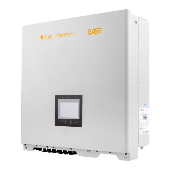
4.2 Product Appearance • Front Object Description Removable front cover LED Light (Three) Functional key(Four) LCD Display • Bottom Object Description DC switch Plug connectors for DC input. Communication interface Terminal for grid connection (AC output) -
Page 16: Product Identification
And the following figure is the side name plate example as on Omniksol-20k- TL2. 4.4 Further Information www.omnik-solar.com If you have any further questions concerning the type of accessories or installation, please check our website or contact our service hotline. -
Page 17: Installation
Installation directly expose under intensive sunshine is not recommended. The installation site MUST have good ventilation condition. 5.2 dimensions, weight Model weight Dimension (L×W×D) Omniksol-15K-TL2 45kg 558mm×560mm×182mm Omniksol-17K-TL2 45kg 558mm×560mm×182mm Omniksol-20K-TL2 45kg 558mm×560mm×182mm... -
Page 18: Mounting Instructions
5.3 Mounting Instructions • Omnik inverter is designed for indoors and outdoors installation • Please mount the inverter in the direction as illustrated above • Install the inverter in the vertical direction is recommended, with a max.15 degrees backwards. • For the convenience of checking the LCD display and possible maintenance activities, please install the inverter at eye level. -
Page 19: Safety Clearance
5.4 Safety Clearance Observe the following minimum clearances to walls, other devices or objects to guarantee sufficient heat dissipation and enough space for pulling the electronic solar switch handle. 30cm 30cm Direction Minimum clearance Above 50 cm Below 40 cm Sides 30 cm... -
Page 20: Mounting Procedure
5.5 Mounting Procedure 1) Mark 4 positions of the drill holes on the wall according to the paper installation position scale packed in the carton box. 2) First, according to the marks, drill 4 holes in the wall. Then, place four expansion tubes in the holes using a rubber hammer. -
Page 21: Electrical Connection
3) First check the 4 holes in the backside of the inverter. Then, lift the inverter carefully, align the 4 holes in the inverter and the 4 screws in the wall, and finally attach the inverter to the screws slightly. 4) Please carefully check the accessories and original carton to make sure every necessary part is used and nothing is missing during installation. -
Page 22: Dc Side Connection
Omniksol-20k-TL2 24000W 22/22A In order to reduce the line loss of DC side (no more than 1% of Pin), Omnik suggest that the length of DC cable for each cable section should not exceed the limit below. Length of cable Model 2.5 mm... - Page 23 Connection procedure by MC4: Connect the PV modules and inverter using MC4 connectors below. Connect the positive and negative terminals from the PV modules to positive (+) terminals and negative (-) terminals on Omniksol. Connection Procedure: 1) Switch off the DC breaker and secure against being switched back on inadvertently. 2) Strip the cable 7 mm.
- Page 24 6) Wrest the cap by using the torque of 2.6~2.9NM. 7) After wrest the cap tightly, align the 2 half connectors and mate them together by hand until a “click” is heared or felt. 8) When the separation of connector is necessary, use the specified wrench tool to separate.Please make sure the wedge side of the fingers face the male connector and push the tool down.Then separate the connector by hand.
-
Page 25: Ac Side Connection
Use a residual current protective device (residual operating current: 300mA). In order to reduce the line loss of AC side (no more than 1% of Pout), Omnik suggest that the length of AC cable from the inverter to the distribution box should not exceed the limit below. - Page 26 2) Insert the striped cable into cord end terminal and insert the assembly into barrel. 3) Then the line will like the picture below. 4) Insert the finished 5 lines into AC cover assembly with the following sequence: 5) Open the plastic cover, use slot type screwdriver to press the shrapnel in the indicated position, and then put the line in the right hole, please note the sequence of the line shall in the right order: L1,L2,L3,N,PE 6) Cover the assembly, tightly screwed and then screw the cable gland...
-
Page 27: Display
7. Display 7.1 LCD Panel The display panel composed of three parts: lights, display and buttons. As shown in the Figure. -
Page 28: Indicator
7.2 Indicator The inverter total has three indicators: running lights (green), Fault lights (red), and Communication lights (yellow), as shown in Figure. Tab. Indicator Description Name State Description light Inverter connects to grid normal Running lights dark Inverter don’t connect to grid light Malfunction Fault lights... -
Page 29: Display
7.4 Display Display interface is shown as Figure. Among them, red dashed box is a fixed display area, the rest is menu display area. Menu display area is in response to key operation, while fixed display area does not support control of keypad. 7.4.1 Fixed display area Fixed display area is divided into seven by content, contains Instant power display block, Models and auxiliary information display block, Generation display block, Temperature... - Page 30 C:Generation display block E-total records the total generating capacity of the inverter, E-Today records the day generating capacity of inverter. D:Temperature and time display block Heat sink temperature is in the left side, the internal temperature is in the middle side and the time is in the right side.
- Page 31 State Description wait Initialization, waiting for the grid Inverter has been connected to grid, and is running normally fault Inverter malfunctions upgrade inverter is upgrading process There are three main menus: Info、 Error 、Set. Each main menu consists of several sub-menu items.
- Page 32 b) Type of inverter c) Information of communication module...
- Page 33 d) Version of inverter 2) Error interface The error interface displays fault information, as shown in figure.
- Page 34 3) Set interface Language Reset DC Coef * Auto Test-F Setting menu is consist of twenty-two sub-items, as shown in the form, Safety* Time AC Coef * WiFi Password* DC Coef * Energy Volt Limit* P(F)&Q(V)* Fault Freq Limit * Start Time* Set AC Coef* Mppt Scan...
- Page 35 b) Set Safety Input the passwords first. Select the safety through “ UP” and “DOWN” button and press "ENTER" key, as shown in figure. c) WiFi reset WiFi reset is to reset the WiFi AP address, as shown in figure。 Select “YES” through “UP”...
- Page 36 d) Clear generating capacity Clear generating capacity means clear total generating capacity(E-Total) and clear day generating capacity(E-Today). Select "Yes" through the "UP" and "DOWN" button and press "ENTER" button. e) Clear fault information Select "Yes" through the "UP" and "DOWN" button and press "ENTER" button.
- Page 37 Set AC Coef No need to set this item. g) Set DC Coef No need to set this item. h) Reset AC Coef No need to set this item. Reset DC Coef No need to set this item. Set date and time Press "UP"...
- Page 38 k) Set password Input the passwords first. Press "UP" and "DOWN" button to adjust the first number. Then press "ENTER" to adjust second number. After setting the sixth number, press the "ENTER" key to finish the setting. Set voltage limit Input the passwords first.
- Page 39 m) Set frequency limit Input the passwords first. Press "UP" and "DOWN" button to adjust the first value. Then press "ENTER" to adjust second value. After setting all the values, press the "ENTER" key to finish the setting. n) Mppt Scan Press "UP"...
- Page 40 o) Set protection Input the passwords first. Press "UP" and "DOWN" button to adjust the first option. Then press "ENTER" to adjust the second option. After setting all the options, press the "ENTER" key to finish the setting. p) Auto test Only “CEI 0-21”...
- Page 41 q) Auto test-F Only “CEI 0-21” can use this function. AC Coef No need to set this item. s) DC Coef No need to set this item.
- Page 42 Set P(f)&Q(v) Input the passwords first. Press "UP" and "DOWN" button to adjust the value. Then press "ENTER" to adjust the second value. After setting all the values, press the "ENTER" key to finish the setting. u) Set start time Input the passwords first.
- Page 43 v) Set 10 minutes over voltage Input the passwords first. Press "UP" and "DOWN" button to adjust the value. Then press the "ENTER" key to finish the setting. 2. Curves interface Curve interface draws day power curve, X-axis represents time in 1 hour, from the left, the first is 1:00 to 2:00, and the far right represents the night 22:00.
-
Page 44: State Information
7.5 State Information State Display State information Waiting Initialization & waiting Wait Connect Sec. Connect Normal Normal Normal state SPI Failure: Communication Fails SPI Failure: Communication Fails between M-S between M-S EEPROM R/W Fail EEPROM R/W Fail Relay-Check Fail Relay-Check Fail DC Injection High DC Injection High The result of Auto Test Function is... - Page 45 Consistent Fault:Fac differs for M-S Consistent Fault:Fac differs for M-S Ground I differs for M-S Ground I differs for M-S DC inj. differs for M-S DC inj. differs for M-S Consistent Fault:Fac, Vac Differs for M- Consistent Fault:Fac, Vac Differs for High DC Bus High DC Bus Flash...
-
Page 46: Communication Setting
Name Quantity PV data collector GPRS antenna Rubber washer Omnik provide 2 kinds of GPRS cards. One is a standard GPRS card and the other one has a card slot. Name 14 pin connector I-PEX interface Standard GPRS card... -
Page 47: Installation Of Communication Card
GPRS card with card slot Name 14 pin connector SIM card slot I-PEX Interface The serial number is shown as below. 8.2 Installation of communication card Warning: Before installing the GPRS card to inverter, you must turn off both the AC side and DC side of inverter to make sure personal safety. - Page 48 Unscrew the four screws on the interface panel with the screwdriver as shown in Picture above and keep the screws aside. The standard connector has two holes. Use the single-hole rubber washer to take place of the double-hole rubber washer. Insert the GPRS antenna through the gland and screw the hex nut with a torque of 2.0 N.m.
- Page 49 Connect the data line into the I-PEX interface. While using the second kind of GPRS card, just insert the SIM card into the card slot. Then insert the GPRS card into the inverter. Install the communication box back to the inverter. While the installation is completed, Antenna can be turned in 360 degrees.
-
Page 50: Register On Monitoring Website
8.3 Register on monitoring website The PV monitoring system of Omnik is supported by: IE8, Firefox, Chrome, and Safari. Login the website http://www.omnikportal.com, click register to enter the user registration page, follows the requirements for registration; please fill in the information for register. After successful registration, enter the mailbox and activity the account, then to complete the registration. - Page 51 Choose the account type Remarks: please read the < Omnik service agreement > carefully, the enclosure is the cost list for all the countries; please choose your operators End User means the final user “*” you must fill it...
- Page 52 Fill in the power station information...
- Page 53 Fill in the power station information After the register, you may enter next chapter 8.4 Login Monitoring System.
-
Page 54: Login Monitoring System
8.4 Login monitoring System After the successful register and account activation, open the login interface as below. Input the correct email and code. Enter the PV monitoring system. Then you can monitor and manage the power station. Input the correct email and code Input the email and code Power station list... - Page 55 List of power station Enter the configure Enter the sharing Back to user “company account” Not yet open case interface interface Reset Add one case under your account Navigation Bar...
- Page 56 Change case Energy saving Case info search Real-time power and generated energy switchover Print current figure Power station info Main interface of Power Station...
- Page 57 Internal temperature Latest data collecting time Real Time Interface Parameter options Choose the aim inverter History Interface...
- Page 58 Alert Interface System Setting Interface...
-
Page 59: Wifi Card
Add serial number 8.5 WiFi card WiFi card is an optional device. If your inverter had installed the WiFi card, please go to 8.6. Network Settings. If your inverter had not installed the WiFi card, please go to 8.2. Installation of communication card first, then go to 8.6. -
Page 60: Netwoek Settings
WiFi card is shown as below: Name 14 pin connector Reset Button I-PEX Interface 8.6 Netwoek Settings Prepare a computer or device, e.g. tablet PC and smart phone that enables WiFi Obtain an IP address automatically Open Wireless Network Connection Properties, double click Internet Protocol Version ... - Page 61 Open wireless network connection and click View Wireless Networks Select wireless network of the data logging module, no passwords required as default. The network name consists of AP and the serial number of the product. Then click Connect.
- Page 62 Connection successful Notice: If AP_ (serial number of product) is not available in the wireless network list, there may be problems in the connection or setting of data logging module. Please check if the WiFi had installed ok, and inverter has been powered on.
- Page 63 Before troubleshooting, please inquire with your inverter installer whether you are allowed to remove the cover of the inverter to trouble shoot the module. If not allowed, please contact customer service. Set parameters of WiFi module (a) Open a web browser, and enter 10.10.100.254(the Default IP address of WiFi card, you may set domain name access, please see the picture 6-14), then fill in username: admin and password: admin, both of which are admin as default.
- Page 64 Click Wizard to start Click Start to continue...
- Page 65 Click Refresh to search available wireless networks...
- Page 66 Next Select the wireless network you need to connect, then click Notice: ① If the signal strength (RSSI) of the selected network is <10%, which means unstable connection, please adjust the antenna of the router, or use a repeater to enhance the signal. ②...
- Page 67 Enter the password for the selected network, then click Next Select Enable to obtain an IP address automatically, then click Next Notice: ① Turn off the firewall of the router ② Make sure the DHCP function of the router is enable...
- Page 68 If setting is complete, the above page will display. Click OK to restart. If setting is complete, the above page will display. After your WiFi card set ok and get IP address from your router for example: 192.168.16.8, (You may see the IP address from inverter)
- Page 69 Input: http://192.168.16.8/ will display the following page:...
-
Page 70: Rs485 Card
You may also add your domain name of WiFi card to easy access according below picture , after you set ok, input http://wifi, you may also access the related page. Now we finish the network setting, please go to 8.3. Register on monitoring website. 8.7 RS485 card... -
Page 71: Recycling And Disposal
RS485 card is an optional device. RS485 card has two RJ45 ports and one USB port. The USB port is used to update the inverter. The RJ45 port is used to communicate with WiFi kit or GPRS kit. WiFi/GPRS Kit You can get more information in the user manual of WiFi/GPRS kit. -
Page 72: Troubleshooting
10. Troubleshooting Fault Fault Info On Possible Reasons Solutions 1.Restart to check Display GFCI Device Fault Inverter GFCI Detector Issue 2.Re-Flash software 3.Replace part or inverter Restart to check after local grid is No Grid or Local Grid Island Fault stable Frequency Isn't Stable Close the protection from the inverter... - Page 73 1.Correct The Installation (Remove DC Voltage Is Too High Due To Panels) PV Volt High Wrong Installation 2.Re-Flash Software 3.Replace Part Or Inverter Grid Voltage Detection Within Change the grid voltage protection Grid Volt Fault A Period Is Anomalous range 1.Remove this Fault Impedance To Ground Between 2.Change it to another standard with...
-
Page 74: Abbreviation
11. Abbreviation Liquid Crystal Display Light Emitting Diode MPPT Maximum Power Point Tracking Photovoltaic Voltage at the DC side Voltage at the AC side Vmpp Voltage at the Maximum Power Point Impp Amperage at Maximum Power Point Alternating Current ( Form of electricity supplied by Utility Company ) Direct Current ( Form of electricity generated by PV modules ) Switch in the DC Circuit. -
Page 75: Contact
+86-512-6956-8216 Fax: +86-512-6295-6682 E-mail: sales @omnik-solar.com sevice@omnik-solar.com Website: www.omniksolar.com Omnik German branch Address: Omnik Gmbh Forsthausstr.8A 65479 Raunheim Tel: +49(0) 1799762654 Mobile: +49(176) 30743149 E-mail: jingjing.zhang@omnik-solar.com Omnik UK Service Partner Address: 3 More London Riverside SE1 2RE,London Tel: +86 512 69568216 8833 E-mail: Frank.Liu@omnik-solar.com... - Page 77 GUARANTEE CARD Agency retention ------------------------------------------------------------------------------------------------------------ 的 User information 得 Product Model Product ID Purchase Date Customer Name 的 Historical Warranty 的 Warranty date Troubleshooting Finished date Customer Signature Client retention...
- Page 78 的 User Information 得 Product Model Product ID Purchase Date Customer Name 的 Historical Warranty 的 Warranty date Troubleshooting Finished date Customer Signature -------------------------------------------------------------------------------------------------------------------------------------------------------------------------------- Warranty Terms 的 的 1. Please fill in this card carefully and read the following warranty terms carefully to ensure that the product is effectively guaranteed.
Need help?
Do you have a question about the Omniksol-15k-TL2 and is the answer not in the manual?
Questions and answers